Hybrid DJ DM3P User manual

3+1 CHANNEL DJ MIXER
DM3P
ENGLISH

PAGE 2

DM3P - DJ SERIES MIXERS
PAGE 3
OPERATION MANUAL
Dear customer,
Congratulations on the purchase of this quality mixing desk. To meet your requirements, this unit has been designed and built to
the highest standards, so that we can assure you that you have made a good and satisfying investment. To take full advantage of all
possibilities and for your own safety and the safety of your environment, please read these operating instructions carefully before you
start using the unit.
This 3+1 Channel Stereo mixer offers two stereo inputs plus one microphone input, and - depending on the version - an additional AUX
music input or an in-built MP3 player. The simplicity of operation but integrity of features make this mixer a great choice for beginners
or occasional users.
1. Read this manual completely before using the product.
2. Keep this manual in your records for future reference.
3. Follow all instruction printed in this manual, otherwise warranty may be void.
4. Follow all printed security advice on the product itself. The lighting flash with arrowhead within an equilateral
triangle makes you aware of non-insulated AC mains voltage inside the unit. The exclamation mark within
an equilateral triangle makes you aware of important operating and maintenance instructions in the
literature attached to this product.
5. Take care of enough distance between this product and sources of hum and noise like electric motors and
transformers.
6. Carry this product with greatest care. Punches, big forces and heavy vibration may damage this product mechanically.
7. The manufacturer takes no responsibility for injury or damage caused by not following the safety precautions and
instructions printed in this manual.
General Advice:
INTRODUCTION
PRODUCT DESCRIPTION
SECURITY ADVICE BEFORE USE
WARNING!
Hazardous voltage. Risk of severe or fatal electric shock.
DANGER!
Safety hazard. Risk of injury or death.
Warning: Read this section carefully before installing, powering, operating, cleaning or servicing this product!
The following symbols are used to identify important safety information in this manual:
WARNING!
Read manual before installation and
operation.
WARNING!
Fire hazard.

PAGE 4
1. Only connect this unit to a mains socket outlet with protective earth connection, ground-fault (earth-fault) protection
and overload protection.
2. Where the mains plug or an appliance coupler is used as a dis-connect device, the disconnect device shall remain
readily operable.
3. To pull the AC Cord out of the wall outlet or the unit’s AC socket, never pull the cable itself, but only the AC plug.
4. Disconnect the unit from AC supply by pulling the AC plug out of the wall outlet or the unit’s AC socket before any kind
of cleaning on the product. Use smooth and dry cloth only for cleaning.
Check all connection cables before reconnecting the unit.
5. Do not expose this unit to any dripping or splashing liquids, and do not place objects filled with liquids, such as vases,
on the unit. Do not operate this unit near to open water or in high humidity.
6. Choose the position of the AC cord according to the lowest risk of damage by foot steps or by squeezing it.
Take especially care of the AC cord outlet on the unit as well as the AC plug and wall outlet at the other end of
the cable.
7. Do not open the unit for service purpose, as there are no user-serviceable parts inside. Warranty will be void in
any case
1. Take care of not placing the unit near sources of heat (e.g. powerful amplifiers, fog machines).
2. Take always care of sufficient air convection in the unit’s environment to avoid overheating, especially when mounting
in a closed environment. Make sure air convection slots – if any - are not blocked. Do not operate this unit in
environmental temperatures exceeding 40 degrees Celsius.
3. Check the total maximum power of your AC wall outlet if you connect several units to one wall outlet and avoid
any overloading.
1. Never use any accessories or modifications not authorized by the manufacturer of this unit.
2. Choose a location for operation where the unit is protected from vibration and where a fixed mounting position
is provided.
3. Before plugging the AC cord in the wall outlet, check whether the AC mains voltage and frequency is the same as this
product is specified for. Whenever your AC plug should not match the wall outlet, contact you dealer immediately.
4. If fluids have spilled into the unit or small parts have intruded the unit, immediately switch off the unit and hand it over
to the authorized service for a security check.
5. Disconnect the unit from AC supply by pulling the AC plug out of the wall outlet or the unit’s AC socket during a
thunder-storm in order to avoid any damage on the unit due to AC voltage peaks.
6. In cause of not correct function of this unit or damaged AC cord or other damaged parts, pull immediately the AC plug
out of the wall outlet and hand the unit over to the authorized service for a security check.
7. To meet all aspects of functionality and security during mainte-nance work to be performed on this unit, all parts
should be replaced by genuine spare parts. Consequently, take care of your dealer or maintenance company to be
authorized by the manufacturer.
This unit produces and absorbs electromagnetic radiation. The strength of radiation and the sensitivity for disturbing interference
matches the CE and FCC requirements. A corresponding sign is printed on the backside of the unit. Any change or modification may affect
the behavior of the unit concerning electromagnetic radiation, with the CE requirements eventually not to be met any more.
The manufacturer takes no responsibility in this case.
This unit is immune to the presence of electromagnetic disturbances – both conducted and radiated - up to a certain level. Under peak
conditions, the unit is classified to show a “class C” performance criteria and may encounter temporary degradation or loss of function
which may need manual help to recover. In such case, disconnect the AC power from the unit and reconnect it again to recover.
This unit is build to conform to the ROHS standards and the WEEE directive 2002/96/EC of the European Parliament and of the
Council of the European Union. Under these regulations, the product shall not be discarded into regular garbage at the end
of its life, but shall be returned to authorized recycling stations.
HEALTH ADVICE
FUCTIONAL ADVICE
ENVIRONMENTAL ADVICE
PROTECTION FROM ELECTRIC SHOCK
PROTECTION FROM FIRE
PROTECTION FROM INJURY & DAMAGE

DM3P - DJ SERIES MIXERS
PAGE 5
USER INTERFACE
Please check that the box contains the following items:
Main parts: 1 pcs. 3+1 channel mixer main unit
1 pcs. AC/AC adaptor
1 pcs. Operation manual
If any part is missing, please contact your dealer immediately for replacement.
Warning: After unpacking, and before plugging the AC/AC adaptor in the wall outlet, check whether
the AC mains voltage and frequency is the same as this products’ AC/AC adaptor is specified for (see
label on AC/AC adaptor). Whenever the specified voltage or the AC plug of the AC/AC adaptor should
not match the local conditions, do NOT plug the AC cord into the wall outlet and contact your
dealer immediately.
UNPACKING

PAGE 6
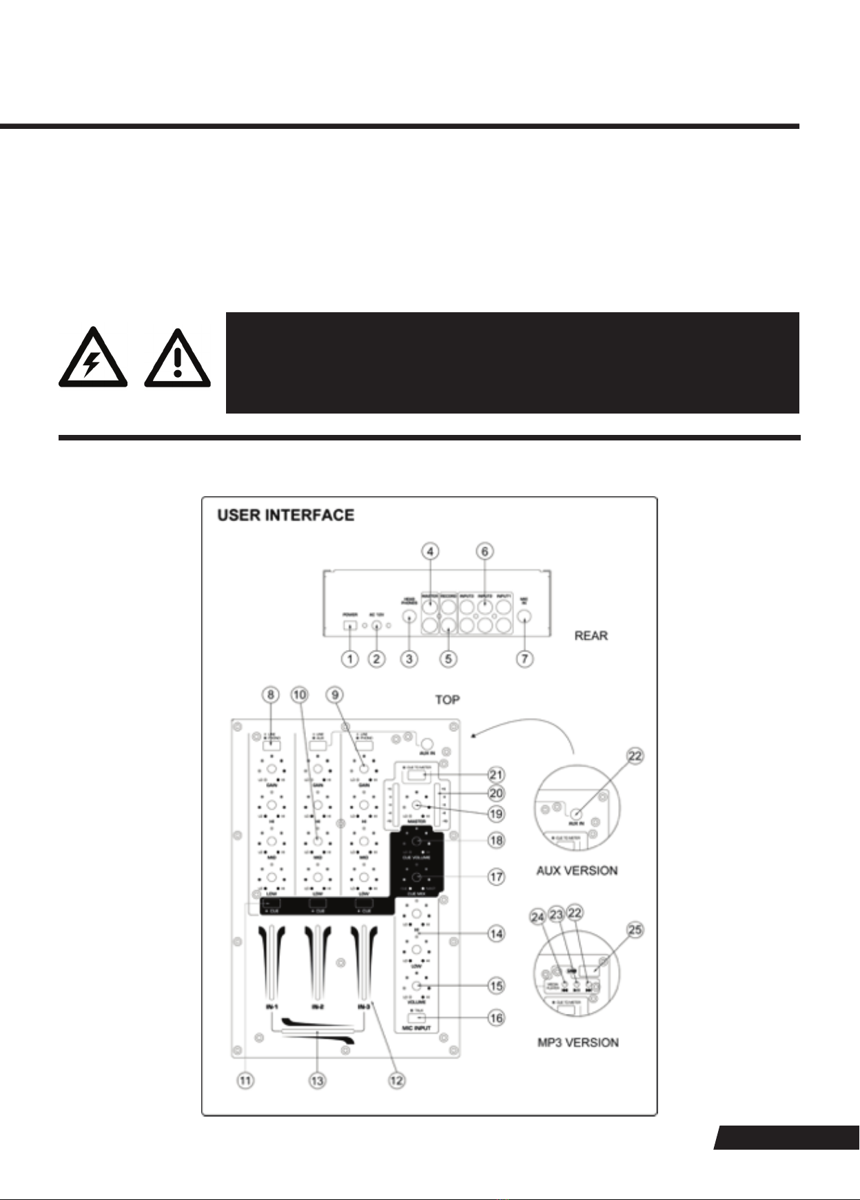
1. Power switch. Switches the unit on and off. Make sure to switch the unit off when not in use.
2. AC input. Connect the supplied AC/AC power supply unit here. DO NOT use any other power supplies than the supplied one or a
genuine spare part.
3. Headphones output. A ¼” TRS connector to connect a headphone. Turn the CUE level (15) down before plugging in
any headphones.
4. Main stereo output. This is an unbalanced output, with its level adjustable by the Master volume control (19).
5. Record output. This is an unbalanced stereo output carrying the same signal as the main output (4), but not influenced by the main
volume control (19). This is normally used for recording the output to an external tape, CD or memory device.
6. Line inputs. These RCA connectors provide inputs for line-level signals to the assigned channels. The input sensitivity can be
switched to PHONO (with RIAA equalization) by means of the input switches (8).
7. Microphone input. This is an unbalanced TRS connector without phantom power provision, hence only suitable for
dynamic microphones.
8. PHONO/LINE selector switches for line inputs. These switches change the sensitivity of the line inputs between PHONO (RIAA
equalized) and LINE level. In released status, the input sensitivity is set to LINE and the indicator LED inside the switch is off, in
pressed status, the input sensitivity is set to PHONO and the indicator LED inside the switch is lit.
9. Gain control of input channels. Allows adjustment of the input sensitivity to compensate for different source volumes. To facilitate
proper setting of input gain levels, the headphone bus (CUE) and thus the input level can be routed to the LED meter by the meter
source switch (21).
10. Channel Equalizer. Allows the adjustment of the tonal balance for each of the stereo inputs in three music-specific frequency
bands with an adjustment range of -26/+12dB.
11. CUE switch for stereo channels. Assigns the respective channel to the headphone bus for pre-fader-listening (CUE). A LED
indicates the pressed position.
12. Channel fader for input channels. A high-grade 45mm fader determines the volume of the respective channel.
13. Crossfader. A high-grade 45mm fader determines the mix ratio between the stereo signals of channel 1 and channel 3.
14. Microphone tone control. Allows tonal adjustment in two voice-specific frequency bands with an adjustment range of ±12dB.
15. Microphone level control. Sets the microphone level.
16. Talkover switch. This momentary switch allows to reduce the music level by 20dB during the switch is pressed, when an
announcement is made through the microphone.
17. CUE Mix control. This control determines the mix ratio between the Main signal and the CUE signal on the headphones. If you
wish to only hear the CUE signal (which contains all channel signals of those channels where the CUE switch (11) is pressed), turn
the control to fully left position, if you wish to only hear the Main Output signal, then turn to the fully right position. Any position in
between delivers a mix of the two signals.
18. CUE volume. Determines the signal volume at the headphone output (3). Always set this control to minimum before putting on
headphones, as sudden high-volume impact may damage your ears. See further health advice below.
19. Main output level control. Determines the main output level present at output (4).
20. Level meter. Depending on the setting of switch (21), this meter will either display the level on the Main output (4) or the level of
the CUE signal (which contains all channel signals of those channel where the CUE switch (11) is pressed).
21. Meter source switch. Decides whether the master output signal (4) is displayed in stereo on the level meter (20) or whether the
level of the CUE signal (which contains all channel signals of those channels where the CUE switch (11) is pressed) is displayed
on the level meter (20). In released position, the master signal is displayed, in pressed position, the CUE signals is displayed and
the indicator LED inside the switch it lit.
For versions with AUX input:
22. AUX input. This is a 3.5mm Mini TRS socket, designed to accept line level signals as for example from mobile media players or
mobile CD players. This input is a switchable input option for stereo input channel 2.
22. SKIP FWD key. Press this key to jump to the next track stored on the MP3 memory source.
23. Play/Pause key. Start the replay or pause the replay of the currently chosen MP3 track.
24. SKIP BWD key. Press this key to jump to the previous track stored on the MP3 memory source.
25. USB (type A, female) socket to allow connection of a flash memory device (USB stick).
For versions with MP3 player:

DM3P - DJ SERIES MIXERS
PAGE 7
CONNECTIONS
For connecting this unit to AC mains, please note that before plugging the AC/AC adaptor in the wall outlet, check whether the AC mains
voltage and frequency is the same as this products’ AC/AC adaptor is specified for (see label on AC/AC adaptor). Whenever the specified
voltage or the AC plug of the AC/AC adaptor should not match the local conditions, do NOT plug the AC cord into the wall outlet and
contact you dealer immediately..
For making audio signal connections, always remember that good and reliable connections are a basic requirement for good sound and
reliable operation. Bad soldering of cables can result in intermittent audio signals or temporarily lost ground connections, hence always
use good cables. In case of doubt about making proper connections, please see check the standard pin assignments required for proper
operation in the appendix of this manual.
POWERING UP
Following a proper power-up sequence protects your equipment – specifically speakers – and your ears. Follow the below procedure:
1. Turn down all output volume controls of any equipment in your audio system.
2. Switch on your audio sources first (Turntables, CD Players, PC’s with soundcards, Tapedecks, etc.)
3. Switch on the audio mixer
4. Switch on any audio processor between the mixer and the amplifier(s) [if any].
5. Switch on the amplifier(s).
6. Turn up the audio level on your sources if such controls are provided.
7. Set the audio output of your mixer to a low level.
8. Set the audio output of any audio processor between the mixer and the amplifier(s) to a medium level [if any such processors].
9. Turn up the volume controls of your amplifier(s) slowly.
10. Make adjustments to all volume settings as needed.
For switching off, follow the inverse sequence – always switch off your amplifier(s) first, then any processors between mixer and
amplifier(s), then the mixer, then the sources.
The MP3 player option can not be retrofitted. If your product is delivered with an AUX input, it can not be modified to add the
MP3 player. For proper replay, please note that:
1. The maximum size of the source flash memory can not be bigger than 32MB; for some flash memory brands, the maximum size
may be smaller (8/16GB).
2. The maximum supply current to the USB bus is 50mA. This is NOT suitable to connect a hard disc or similar devices – only flash
memory is permitted.
3. certain brands and types of flash memory may not be compatible with this player. Preferably, well known branded USB sticks
shall be used. Avoid to use USB adaptors for SD cards, micro-SD cards etc.
4. You must apply proper alphanumerical file names to your MP3 files if you want them to be played in a certain sequence.
5. This MP3 player does not recognize folders. All MP3 files must be stored in the root directory of the memory.
General notes for the MP3 version:
OPERATION
Apart from using good equipment, good sound comes from using it correctly. Level setting mistakes are one of the common reasons
why even good equipment may not perform as desired. For setting levels, please be reminded that two guidelines need to be followed:
1. Avoid distortion by leaving some headroom. Never overrun any audio-equipment’s inputs. Level meters and displays allow you to
make sure that signals do not enter critical levels.
2. Avoid unnecessary amplification by using as little attenuation as possible. For example, if you turn down the input gain of a mixer
to minimum, and then increase the main output of the mixer to maximum to drive your amplifier properly, you will create unnecessary
noise, as you first dispose of some already existing signal level, and then later apply amplification (tainted with noise) to make it up.
Obviously, these two requirements are marking a levelling window that the operator must match to achieve a good sound with as little
distortion and noise as possible.
DANGER: Excessive volume levels on headphones or other sound systems may
cause hearing damage. Always turn the volume control to minimum when you
switch the unit on, and do not exceed healthy listening levels.

PAGE 8
MAINTENANCE AND WARRANTY
While we have chosen the best components to make this product as rugged and reliable as possible, some parts in audio products
(potentiometers, faders, switches) are subject to wear which is a matter of operation cycles, and not of time. While providing a full time-
based warranty according to the country’s of purchase requirements on the function of the electronic circuitry, we hence have to limit
the warranty on such electro-mechanical parts to 90 days from the date of purchase.
In many cases, malfunction of electro-mechanical parts occurs due to dust contamination, which may require cleaning of such parts.
As the inside of such parts is not accessible, a common practice is to use cleaning fluids in the shape of sprays. Please be reminded
that many of such fluids contain chemicals which may wash away the dust but at the same time corrode or damage contact surface and
may cause cosmetic damage to other parts. We hence explicitly exclude any claims for exchange of damaged part due to mechanical or
chemical impact.
Without liability, we recommend CaiLube MCL fader cleaner and lubricant available from CAIG Laboratories if the need of cleaning for
electro-mechanical parts occurs.
Further to that, this unit does not need regular maintenance.
Mains Input EU version:
Mains Input US version:
Power consumption:
Frequency response:
S/N:
THD+N:
Dimensions:
Weight:
AC220-250V~ 50Hz
AC110-120V~ 60Hz
max. 4W
20Hz-20kHz ±1.0 dBu
>75dB
< 0.07% @ 1kHz
W 178× H255x D 71mm
1.3 kg
Standards
EU safety:
EU EMC:
US safety:
US EMC:
EN 60065:2001 +A1
EN55103-1:1997, EN55103-2: 1997
UL60065
FCC Part 15
This product meets both the EMC Directive 2004/108/EC and the Low Voltage Directive 2006/95/EC.
For further information ask your dealer or visit the website of the manufacturer.
TECHNICAL DATA

DM3P - DJ SERIES MIXERS
PAGE 9

www.vivaafrika.co.za
DJ MIXERS
PROFESSIONAL
Table of contents
Other Hybrid DJ Dj Equipment manuals