USER MANUAL - OPAL-22 AUDIO INTERFACE
PAGE 4PAGE 3
SOFTWARE INSTALLATION
Note: the drivers must be installed before connecting the OPAL-22 to the PC:
Download the latest driver package from the http://vivaafrika.co.za/downloads/
Locate the driver installation file and double-click its icon to begin the installation
Follow the on-screen instructions to perform the installation
When the installation is complete, restart your computer
After restart, connect the OPAL-22 to your computer
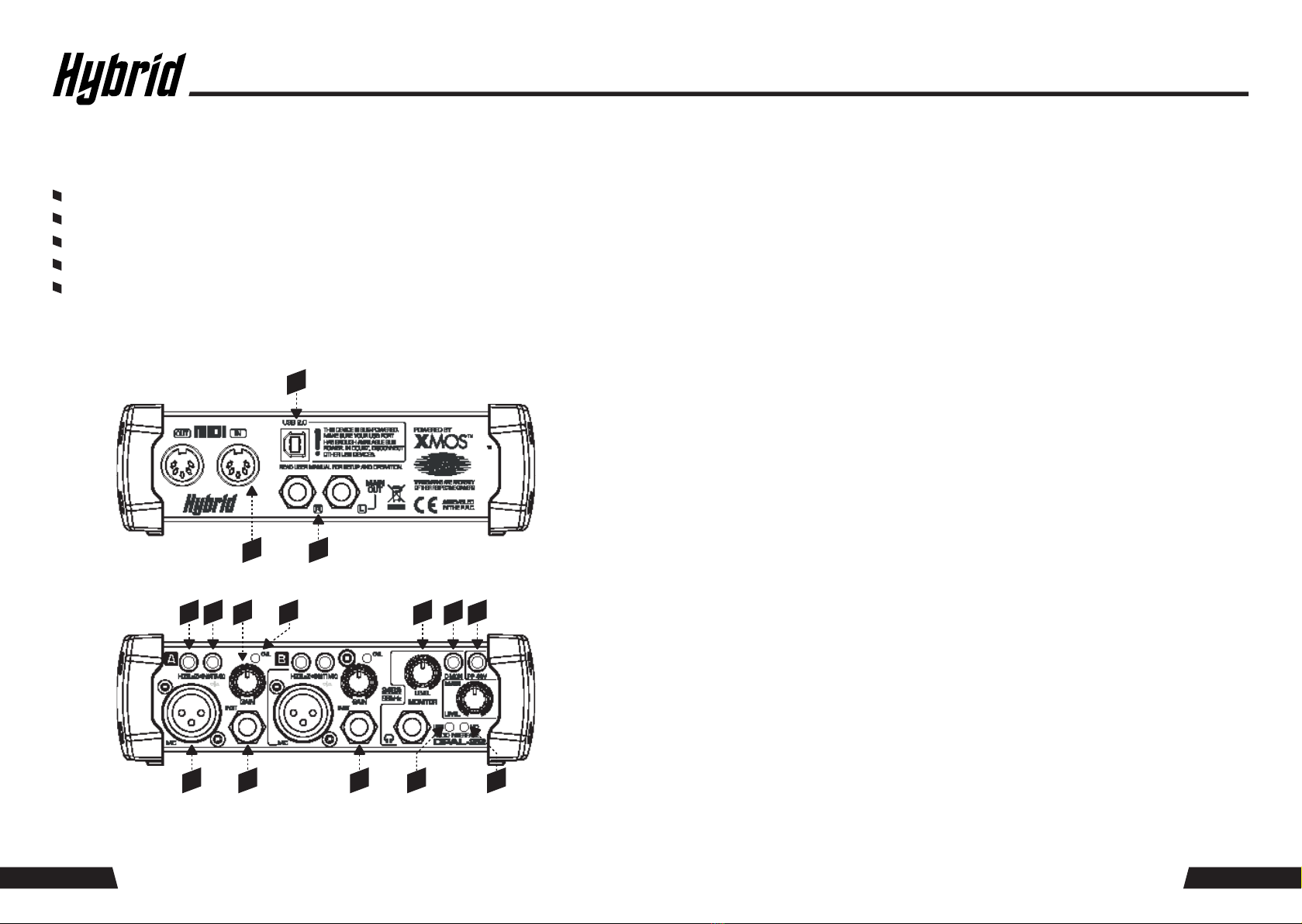
USER INTERFACE ELEMENTS
Connections - Rear Side
Controls - Front Side
1
23
611712 138
4 5 15
9
10 14
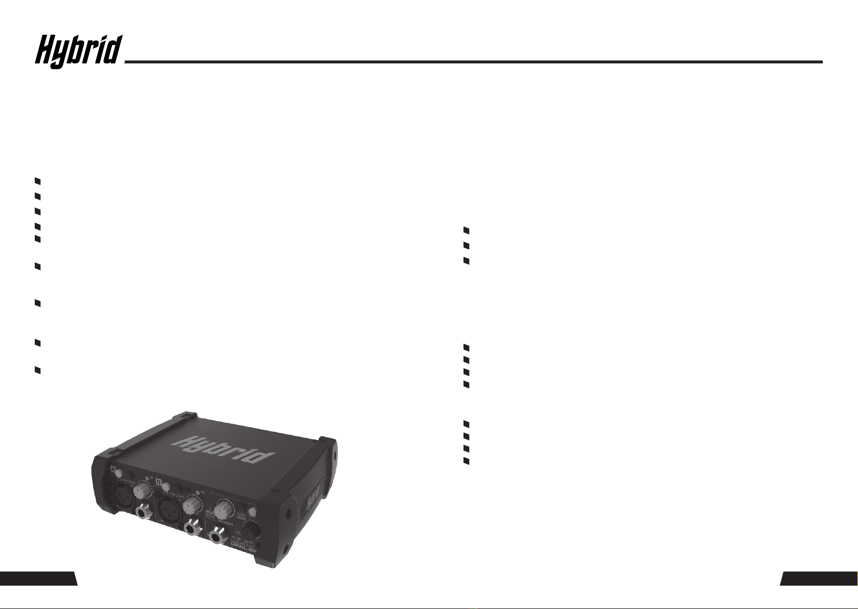
FUNCTIONAL DESCRIPTION
The OPAL-22 allows to pre-amplify and record two analog audio signals into a connected PC via a USB
2.0 connection with low latency ASIO technology (PC only). Branded converters with high resolution and
sampling rate grant pristine and untainted signal quality. To prepare the recording, the input signals can
be monitored directly. To complete the PC connectivity, a MIDI interface is built in.
NOTE: Below description of functional element 4 to element 9 refers to the Input section (A) as pictured
opposite. All elements for input section (B) are identical.
1: USB 2.0 port. This is a type B connector for connection to a PC with the supplied cable.
2: MAIN OUTPUT. This is a pair of ¼” (6.35 mm) balanced TRS jack sockets. These jacks carry the same signal
as the monitor jack (10), but cannot be controlled locally in terms of volume, and are not affected by the
direct monitor switch (12).
3: MIDI interface. This is a pair of standard 5-pin DIN connectors. Allows the connection of compatible MIDI
equipment for receiving and sending MIDI information from and to the connected PC.
4: Microphone input. This is a standard female balanced XLR connector to connect dynamic or condenser
microphones. Phantom power for condenser microphones can be activated via the switch (13).
Keep phantom power off when using with dynamic microphones.
5: Instrument input. This is a ¼” (6.35 mm) balanced TRS jack. The impedance of this input is switchable to
match high- or low-impedance sources via the switch (6).
6: Impedance switch for instrument input. Switches the input impedance to match high- or low-impedance
sources connected to the instrument input (5).
7: Instrument/Mic input selector. Determines whether the microphone input (4) or the Instrument input (5)
is the active input.
8: GAIN control. Sets the input gain for the chosen active input. Observe the Overload (”OVL”) LED (9) while
setting the gain, to make sure that the LED only lights up occasionally at the highest peak levels of the input
signal, in order to find the best gain setting.
9: OVL (Overload) LED. Indicates when the GAIN control (8) is set too high and internally safe signal levels
are exceeded.
10: MONITOR output. Carries the same signal as the MAIN output (2), but can be adjusted in its volume via the
monitor volume control (11). Further, the inputs can be routed directly to the MONITOR output when the
D-MON switch (12) is pressed.
11: MONITOR LEVEL. Determines the volume at the monitor output (10).
12: D-MON switch (direct monitoring). Adds the input signals of input section A and B to the monitor
output signal. If monitoring of the input signals only is required, mute the replay of audio from your DAW
on your PC.
13: Phantom Power switch. Activates +48V DC phantom power supply to the microphone inputs (4).
Only for use with condenser microphones which require phantom power. Keep this switched off when
using dynamic microphones.
14: USB bus activity LED. Indicates ongoing data traffic on the USB bus.
15: MIDI bus activity indicator. Indicates ongoing data traffic on the MIDI bus.