Hyco Wave HW30A Specification sheet

Product Instruction Manual
Wave
HW30A & HW30M
3kW Instantaneous Hand Wash unit
Version 3.2 Jan 2015
V21.9.3

2
Thank you for purchasing a Hyco Wave hand wash unit. The Wave offers
an indefinite supply of hot water thanks to its instantaneous operation.
Without the standing losses associated with storage type heaters, the unit
is a very energy efficient solution for light hand washing at a single basin.
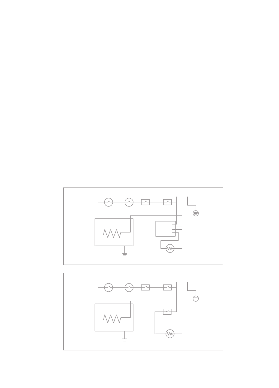
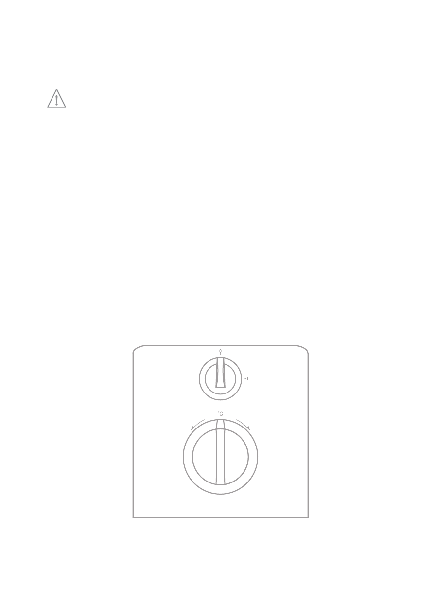
The Wave is available in two models; the HW30A operates automatically
via an infra-red sensor and the HW30M is operated manually via a rotating
knob on the front of the unit. Please read and understand these instructions
before commencing installation and leave them with the user when
installation is complete.
1. Impor an safe y poin s
•Electrical installation must be carried out by a qualified electrician in accordance
with the latest edition of the IET wiring regulations.
•This appliance must be earthed.
•Means for electrical disconnection must be incorporated into the fixed wiring in
accordance with the wiring rules.
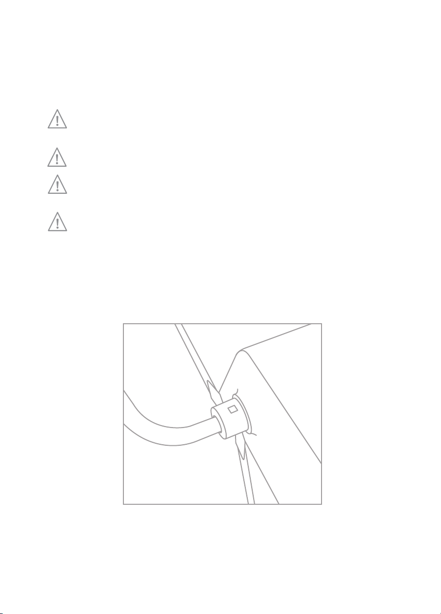
•This appliance is intended as an open outlet heater. Only use the spout supplied
with the unit and do not attempt to modify the spout or the spray head in any
way.
•The spray head must be descaled regularly to ensure it remains unimpeded and
free from debris and to avoid a pressure build up.
•This appliance incorporated a safety relief valve ; do not attempt to modify this
in anyway.
•Do not switch on if there is a possibility that the water in the heater is frozen.
•Do not use the appliance in an ambient temperature exceeding 30°C.
•This appliance can be used by children aged from 8 years and above and persons
with reduced physical, sensory or mental capabilities or lack of experience and
knowledge if they have been given supervision or instruction concerning use of
the appliance in a safe way and understand the hazards involved. Children shall
not play with the appliance. Cleaning and user maintenance shall not be made by
children without supervision.

3
2. Ins alla ion
Wall Moun ing
Select a suitable location for the final positioning of the heater, ensuring the spray will
discharge into a suitable basin/sink during use.
To mount the heater first remove the front cover by unscrewing the two pairs of screws
located at the top and bottom of the heater.
With the cover removed and the mounting position determined, offer the unit to the
wall. Ensure the unit is level (a spirit level is recommended) and mark the two key hole
slots onto the final location surface.
•Always ensure there are no hidden cables or pipes before commencement of drilling.
•Two cable entry points are available on the heater. If a concealed cable is required to
enter through the back of the product the knock out section on the back plate should
be removed to allow cable entry.
Drill the two holes marked in the previous step and insert the wall plugs provided. Offer
up the unit and locate the two screws into the two holes drilled. Screw down until the
heater is firmly fixed to the wall.

Plumbing
Final connection to the water supply should be made by 15mm copper pipe
compression fitting to the cold (right hand) inlet side of the heater.
Do not carry out soldering close to the heater as heat transfer can cause
damage to the unit.
Fit an isolation valve close to the unit, this will aide necessary maintenance.
Before final connection of the water supply to the heater, ensure any debris
such as loose solder is flushed from the system.
Do not use jointing compound for the plumbing connections of the heater.
To fit the spout push in onto the hot water outlet, ensuring the retaining lugs locate and
click into position.To remove the spout gently prise the retaining lugs apart with a pair
of part screwdrivers and separate the spout from the heater.
4
240mm
170mm
100mm
HW30A Infra Red
50 Thermal Cut
Out Auto
Pressure
Switch
Cold
Switch
Heat Element
IR PBC
Switch
90 Thermal Cut
Out Manual
L N E
Solenoid Value
HW30M Manual
ON/OFF
Switch
50 Thermal Cut
Out Auto
90 Thermal Cut
Out Manual
Pressure
Switch
Cold
Switch LNE
Heat Element
Solenoid Value
Press
button
to
reset
Pressure
Value

Electrical
•A cable with a minimum size of 1.5mm2should be used for the fixed wiring of
the heater.
•Electrical supply should be capable of isolation via double poled switch rated
for 13 amps.
•The heater must be earthed.
Select the entry point for the cable; this can be via the concealed entry point in the back
plate or through the cable exit at the bottom right of the heater.
•When using the bottom right cable entry point the cable grip located directly below
the terminal block must be used.
Earth cable to the terminal marked "E" (earth symbol)
Neutral cable to the terminal marked "N"
ive cable to the terminal marked " "
Wiring diagrams are as follows:
5
240mm
170mm
100mm
HW30A Infra Red
50 Thermal Cut
Out Auto
Pressure
Switch
Cold
Switch
Heat Element
IR PBC
Switch
90 Thermal Cut
Out Manual
L N E
Solenoid Value
HW30M Manual
ON/OFF
Switch
50 Thermal Cut
Out Auto
90 Thermal Cut
Out Manual
Pressure
Switch
Cold
Switch LNE
Heat Element
Solenoid Value
Press
button
to
reset
Pressure
Value

Replacing the cover
•Ensure the internal low valve is in the fully closed position (turned clockwise as
far as it will go).
•When the cover is replaced ensure that the temperature/low control knob
on the front cover indicates that the valve is closed.This ensures there is
the correct correspondence between the external indication of the valve
state (open/closed) as seen by the user and the true physical state of the valve
(open/closed).
•Gently engage the temperature/flow control knob on to the valve spindle
as you replace the cover. Check that the valve will now operate fully in
both directions.
•The manual unit HW30M also features a linking rod that connects the on/off
switch with the on/off control knob. The linking rod has a “D” cross section
that ensure it will only connect with the rod in the correct orientation.
•Replace the two pairs of screws on the top and bottom of the unit.
6

3. Opera ion
Commissioning Mo e
On first use the commissioning sequence must be followed to prevent dry
operation of the element.
Turn on the water supply to the unit.
Turn the temperature/flow control knob on the front of the unit "fully" clockwise to the
commissioning setting (°C). This disables the heating element.
Turn on the electrical supply and activate the water flow:
(a) For the automatic unit place your hand close to the circular IR window.
(b) For the manual model turn the power switch clockwise to the ‘ON‘ position
(ON = 1, OFF =0)
Allow the water to flow through the unit until a smooth spray is achieved from the spout
for several seconds.
This completes the commissioning cycle. It must be repeated if the tank is ever drained.
7
240mm
170mm
100mm
HW30A Infra Red
50 Thermal Cut
Out Auto
Pressure
Switch
Cold
Switch
Heat Element
IR PBC
Switch
90 Thermal Cut
Out Manual
L N E
Solenoid Value
HW30M Manual
ON/OFF
Switch
50 Thermal Cut
Out Auto
90 Thermal Cut
Out Manual
Pressure
Switch
Cold
Switch LNE
Heat Element
Solenoid Value
Press
button
to
reset
Pressure
Value

Normal Operation
•Manual Model
Turn on the power to the heater via the top on/off knob. Adjust the temperature
selection knob until the desired temperature is achieved. When hand washing is
complete turn off using the top on/off knob.
•Automatic Model
Turn on by placing the hand near the red Infra-Red window.
Adjust the temperature selection dial until the desired temperature is achieved.
The automatic unit will deliver a timed flow of water for about 30 seconds or until
the unit is switched off by a repeated hand gesture.
Water Temperatures
The Wave hand wash unit is an instantaneous water heater consuming a fixed 2840 kW
of power. This power will raise the temperature of the incoming water by an amount that
reflects the flow rate – a low water flow results in a relatively high temperature uplift and
a high flow results in a relatively low uplift.
The delivered temperature = the incoming water temperature + the uplift.
Therefore in winter when incoming water temperatures drop the flow rate will need to be
reduced to maintain the same delivered water temperature.
4. Main enance
Descaling the Spray Hea
The spray head will require de-scaling from time to time; failure to do so could result in
an internal pressure build-up.
To carry out de-scaling of the spray head, unscrew the central screw in the sprayhead
and remove any solid debris under a running tap.To remove stubborn scale it may be
necessary to use a suitable hard brush or to soak the parts in a proprietary de-scaler
solution (available in eg supermarkets).
Cleaning
Wipe surfaces with a damp (not wet) clean cloth. Do not use abrasive compounds.
8

Safety Features
The Wave hand wash unit is fitted with two levels of thermal protection, the first is a
self-resetting cut-out that will operate at 60°C and the second is a manual resettable
cut-out that operates at 90°C.
•Automatic Thermal Cut-out
If the automatic resettable cut-out operates the element will not operate until the
water cools back down below around 30°C. Allowing the water to flow for several
seconds will achieve this. If the problem persists then adjust the temperature down
using the temperature selection control.
•Manual Reset Thermal Cut-out
If the manual reset thermal cut-out
operates the unit will cease to heat
and will not reset automatically.
To perform a manual reset it is
necessary to remove the front
cover in order to access the reset
button.
Do not attempt to reset the manual cut-out unless the power has been
isolated from the unit.
Once the cover is removed the manual reset thermal cut-out can be reset with a push
of the button.
In the case of a manual reset event, the cause should be established before
continuing usage. A low flow or obstruction in the spray head is the most
likely cause and this problem should be rectified prior to re-using the heater.
If in doubt contact Hyco technical support on 01924 225215.
9
240mm
170mm
100mm
HW30A Infra Red
50 Thermal Cut
Out Auto
Pressure
Switch
Cold
Switch
Heat Element
IR PBC
Switch
90 Thermal Cut
Out Manual
L N E
Solenoid Value
HW30M Manual
ON/OFF
Switch
50 Thermal Cut
Out Auto
90 Thermal Cut
Out Manual
Pressure
Switch
Cold
Switch LNE
Heat Element
Solenoid Value
Press
button
to
reset
Pressure
Value

10
Pressure Relief Valve
The Wave hand wash unit also incorporates a pressure relief valve.
In the event of an over pressure event a small silicone ball will be expelled from the unit
which will allow the unit to release the pressure build up.
If the valve does operate the reason for the discharge should be established and
rectified before replacing the relief valve ball (a common cause can be a scaled up
spout head).
The replacement process is as follows:
•Isolate the unit from the power & power supply.
•Using the supplied tool, push the ball into the valve at the base of the tank
(behind the spout) and then push into the valve as far the tool will go allow.
•Reconnect the heater to the power supply and water supply in turn.
•Commission the heater (refer to the earlier section of this manual) and inspect
to ensure it is fixed and no water escapes from the relief valve.
240mm
170mm
100mm
HW30A Infra Red
50 Thermal Cut
Out Auto
Pressure
Switch
Cold
Switch
Heat Element
IR PBC
Switch
90 Thermal Cut
Out Manual
L N E
Solenoid Value
HW30M Manual
ON/OFF
Switch
50 Thermal Cut
Out Auto
90 Thermal Cut
Out Manual
Pressure
Switch
Cold
Switch LNE
Heat Element
Solenoid Value
Press
button
to
reset

11
5. Specifica ions
MODEL Han Wash Automatic Han Wash Manual
(HW30A) (HW30M)
Power Consumption 230V~ 2840W 230V~ 2840W
Max Inlet Pressure 0.6 Mpa 0.6 Mpa
Min Pressure 0.1 Mpa 0.1 Mpa
Temperature Protection 60°C auto 60°C auto
90°C manual 90°C manual
30°C 30°C
Max Ambient
Temperature
240mm
170mm
100mm
HW30A Infra Red
50 Thermal Cut
Out Auto
Pressure
Switch
Cold
Switch
Heat Element
IR PBC
Switch
90 Thermal Cut
Out Manual
L N E
Solenoid Value
HW30M Manual
ON/OFF
Switch
50 Thermal Cut
Out Auto
90 Thermal Cut
Out Manual
Pressure
Switch
Cold
Switch LNE
Heat Element
Solenoid Value
Press
button
to
reset
Pressure
Value

hyco.co.uk
Hyco Manufacturing td
Normandy Court
Express Way
Castleford, WF10 5NR
T 01924 225 200
F 01924 225 210
E sales@hyco.co.uk
INFORMATION FOR CORRECT DISPOSAL OF THE PRODUCT IN ACCORDANCE WITH THE
EUROPEAN DIRECTIVE 2012/19/EU.
At the end of its working life this equipment must not be disposed of as household
waste. It must be taken to a local authority waste collection center or to a dealer
providing this service. Disposing of electrical and electronic equipment separately
enables its components to be recovered and recycled to obtain significant savings in
energy and resources. In order to underline the duty to dispose of this equipment
separately, the product is marked with a crossed out dustbin.
6. Guaran ee and service policy
This product is guaranteed against faulty materials and manufacture for a period of one
year from the date of purchase. Hyco will in its sole discretion replace, repair or refund
any faulty unit. Incorrect installation and failure to follow correct operating instructions
are excluded. Consequential costs such as labour charges or damage to surroundings
are expressly excluded.
This manual suits for next models
1
Table of contents
Other Hyco Plumbing Product manuals
Popular Plumbing Product manuals by other brands

American Standard
American Standard Roselyn Countertop Sink 0498.001 Specifications

Helvex
Helvex FC-185-19 installation guide

Kraus
Kraus Oletto KPF-3104BG installation manual

GESTRA
GESTRA UNA 45 MAX Original Installation Instructions

PEERLESS
PEERLESS PTT4335 Series quick start guide

Hans Grohe
Hans Grohe Ecos 31779007 Instructions for use/assembly instructions