10
Troubleshooting –
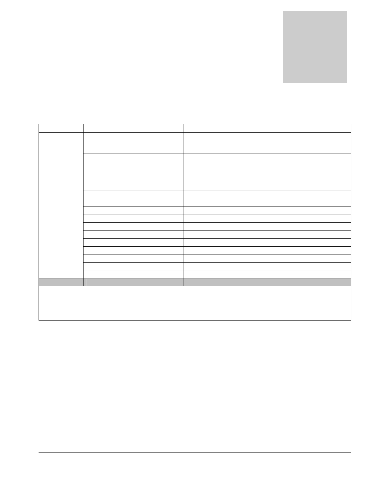
V115 Pump-out
Pump-out not
working Building circuit breaker tripped.
Reset breakers or move cords to other outlets. Repeated
tripping of breaker may indicate a short circuit. Check cord
and unit wiring and repair before using pump-out.*
GFCI tripped
Reset GFCI, replace GFCI or move to other outlet
Repeated tripping of GFCI may indicate a short circuit.
Check cord and unit wiring and repair before using pump-
out.*
Faulty power cord Replace cord (AX33 or NM4407)
Faulty switches or internal wiring Check wiring & test switch - Repair as needed * (NM5008)
Pump-out pump faulty Replace pump-out pump (NM5053)
Pump-out pump clogged Clean pump-out – Clean filter screens - Keep tank clean
Outlet check valve stuck Clean or replace check valve
Discharge hose restricted Un-kink, clean out or replace hose
Float switch stuck Clean switch make sure float slides up & down easily
Float switch faulty Replace float switch (NM5054)
* To reduce the risk of fire electrical shock or injury repairs to wiring should only be performed by
experienced service technicians.
If you are not experienced in checking electrical wiring contact your nearest authorized service
center to perform tests and repairs to cords, wiring and switch.
•Contact your distributor for additional troubleshooting
assistance, to order parts, or for advice and assistance in
performing necessary repairs.
Troubleshooting