2 ZT-2800®/ZT-3100®/ZT-3200TM
-
-
WARNING
Actuating the bypass will result in the
loss of hydrostatic braking capacity. The
machine must be stationary on a level
surface and in neutral when actuating
the bypass.
Introduction
-
®
ZT-2800®®
-
-
Do not use a pressure washer to
clean the unit.
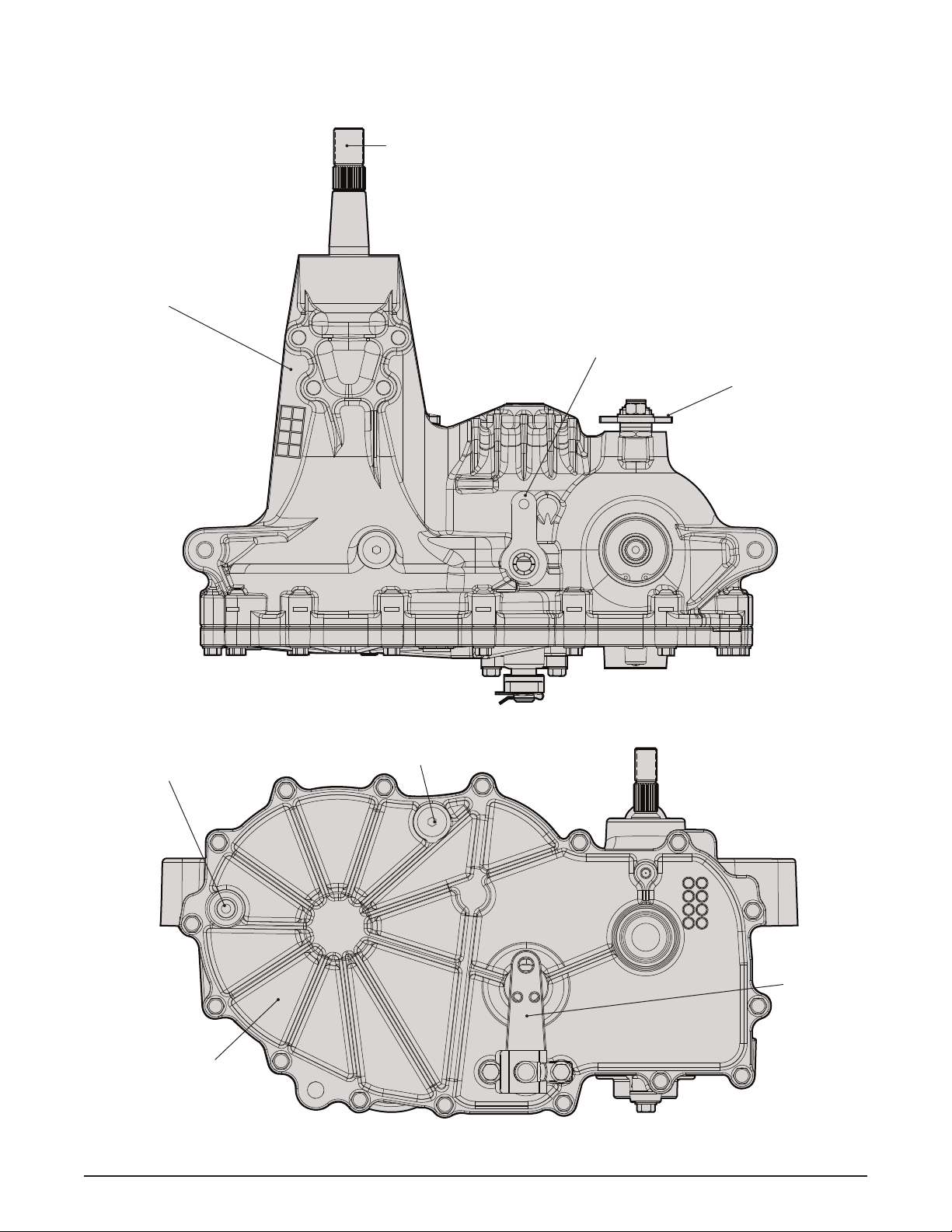
General Description
-
-
-
DESCRIPTION AND OPERATION