2 ZT-2800®/ZT-3100®/ZT-3200TM/ZT-3400®
Both transaxles are fully ooded with oil. A
common external expansion tank assures the
drives’ cool, quiet operation. An external lter on
the transaxle allows for easy oil maintenance.
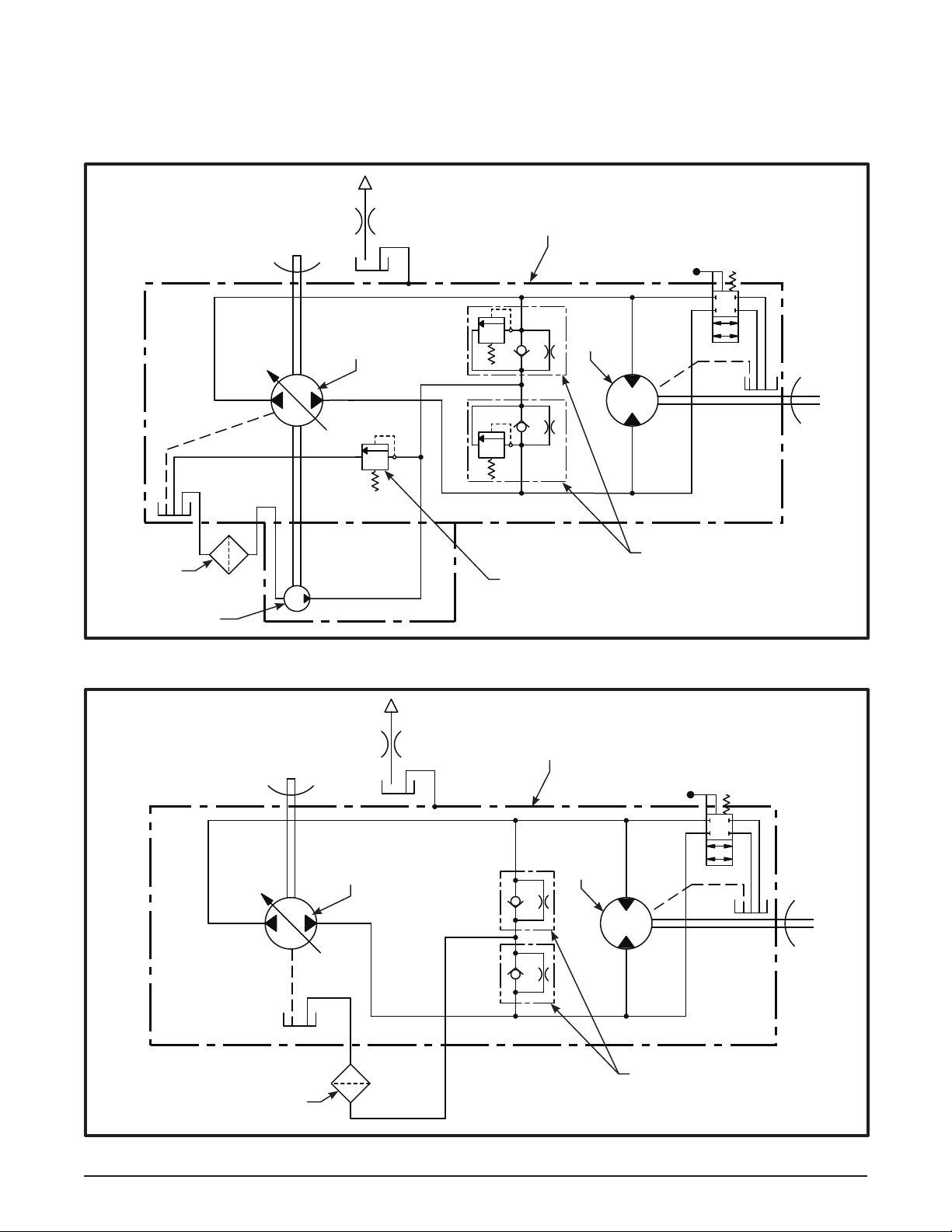
The ZT-2800 is designed for both charged and
uncharged product versions. In the uncharged
consumer vehicle drive, uid passes through
the lter by interaction of the positive head on
the uid from a properly elevated expansion
tank and the negative pressure created at the
pump inlet during piston operation.
Hydro-Gear’s patented charge conguration
is used in the ZT-3100, ZT-3200 and ZT-3400
version. Here, uid is drawn from the case and
through the lter and into a xed displacement
gerotor pump. Charge pump ow not used to
feed the low pressure side of the system is
passed over a charge relief valve and back into
the transaxle case.
The check valves in the center section are used
to control the make-up ow of the uid to the
low pressure side of the loop.
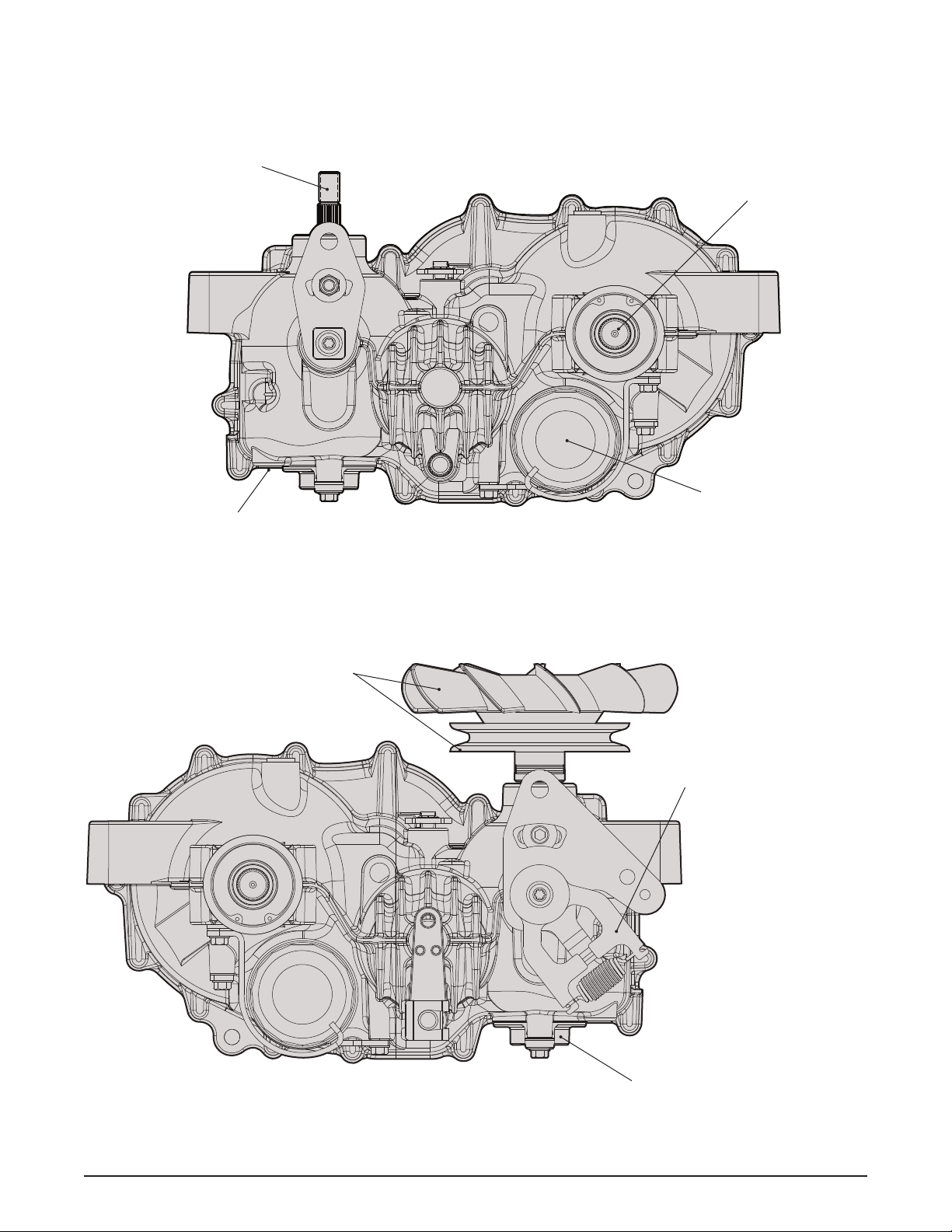
The ZT-2800, ZT-3100, ZT-3200 and ZT-3400
have an internal cog style parking brake. It is
essential to fully disengage the brake prior to
operation.
A cam style, block lifting bypass is utilized in
the ZT-2800, ZT-3100, ZT-3200 and ZT-3400 to
permit moving the vehicle for a short distance at
a maximum of 2 m.p.h. (3.2 Km/h) without start-
ing the engine. The brake must be disengaged
prior to actuating the bypass mechanism.
WARNING
Actuating the bypass will result in the
loss of hydrostatic braking capacity. The
machine must be stationary on a level
surface and in neutral when actuating
the bypass.
Introduction
The purpose of this manual is to provide in-
formation useful in servicing the Hydro-Gear®
ZT-2800®, ZT-3100®, ZT-3200TM and ZT-3400®
Integrated Zero-Turn Transaxles. This manual
includes the general descriptions, hydraulic
schematics, technical specications, servic-
ing and troubleshooting procedures for both
transaxles.
Other than recommended oil and lter changes,
the transaxle normally will not require servic-
ing during the life of the vehicle in which it is
installed. Should other servicing be required,
the exterior of the transaxle will need to be
thoroughly cleaned before beginning most
procedures. Do not wash the transaxle while
it is hot. Do not use a pressure washer to
clean the unit.
General Description
The ZT-2800, ZT-3100, ZT-3200 and ZT-3400
are self contained units designed for the trans-
fer and control of power. They provide an in-
nitely variable speed range between zero and
maximum in both forward and reverse modes
of operation.
The ZT-2800, ZT-3200 and ZT-3100 transaxle
uses a variable displacement pump with a
maximum displacement of 10cc per revolu-
tion. The ZT-3400 transaxle uses a variable
displacement pump with a maximum displace-
ment of 12cc per revolution. Both transaxles
use a motor with a xed displacement of 16cc
per revolution. The variable displacement pump
features a trunnion mounted swashplate with
a direct-proportional displacement control. Re-
versing the direction of the swashplate reverses
the ow of oil from the pump and thus reverses
the direction of the motor output rotation. The
pump and motor are of the axial piston design
and utilize spherical nosed pistons which are
held against a thrust race by internal compres-
sion springs.
DESCRIPTION AND OPERATION