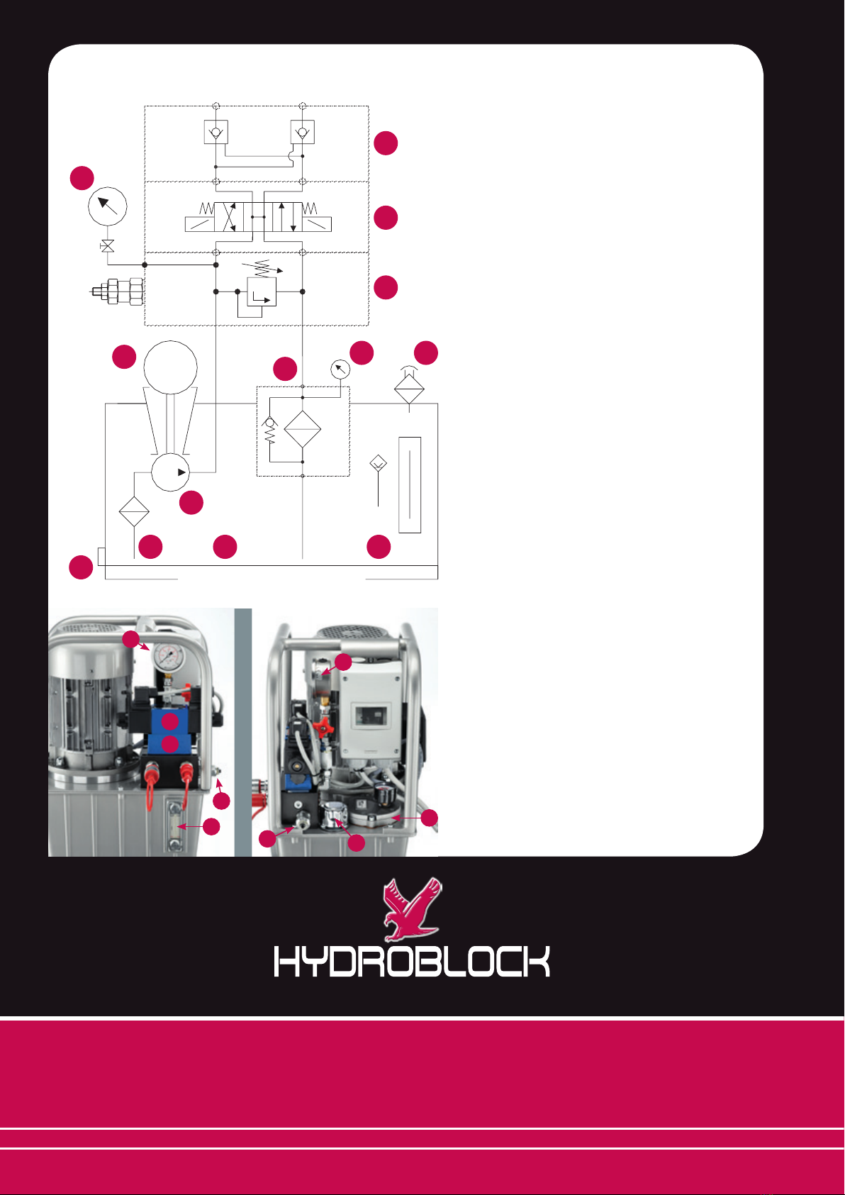
manuals.online logo
Brands
  1. Home
  2. •
  3. Brands
  4. •
  5. HYDROBLOCK
  6. •
  7. Portable Generator
  8. •
  9. HYDROBLOCK CE10 User manual

HYDROBLOCK CE10 User manual

POWER UNIT CE10
RELEASE 09/2012
innovative engineering
Al ne di ottenere un efciente e duraturo funzionamento
delle centraline oleodinamiche è necessario seguire alcu-
ne avvertenze ed istruzioni. Un montaggio razionale ed
una corretta installazione sono fattori essenziali per un
buon utilizzo nel tempo di un impianto oleodinamico.
La polvere, la sporcizia ed i trucioli sono i peggiori nemici
dell’oleodinamica: durante il montaggio osservare quindi
la massima pulizia delle tubazioni, dei raccordi di collega-
mento, delle forature di blocchi o piastre ecc., le opera-
zioni di collegamento devono essere effettuati in un locale
pulito e non polveroso.
Le centraline oleodinamiche vengono sempre consegnate
con tappi di protezione: non asportare per nessuna ra-
gione queste protezioni se non all’atto del montaggio; di
regola non lasciare mai le bocche delle apparecchiature
aperte se non per il tempo indispensabile alla installazione.
Per il collegamento delle apparecchiature oleodinamiche
fare sempre riferimento allo schema oleodinamico.
OLIO IDRAULICO
Usare esclusivamente olio a base minerale ISO 6743/4 -
DIN 51524.
La viscosità consigliata è ISO VG32 per temperatura olio
da 10° a 60°C, secondo ISO 3448.
L’utilizzo di altri uidi non consentiti può danneggiare il
buon funzionamento della centrale.
AVVIAMENTO
Dopo aver collegato il motore elettrico vericare il senso di
rotazione della pompa (con brevissimi impulsi di 1-2 sec
max.) osservando il motore lato ventola, la rotazione deve
essere ORARIA.
NON invertire assolutamente il senso di rotazione neppure
per breve tempo, potrebbe causare la rottura della pom-
pa. Spurgare l’impianto idraulico da eventuali presenze
d’aria ripristinando se necessario il livello dell’olio dopo i
primi azionamenti. Lo sato va effettuato mediante appo-
site viti posizionate in zone elevate dell’impianto o, dove
non previste, allentando i raccordi d’attacco agli attuatori
(cilindri o motori).
Ricordiamo che l’aria racchiusa nel circuito, a causa della
sua comprimibilità, è origine di vibrazioni, rumore, funzio-
namento difettoso ed usura rapida dei componenti.
USO E MANUTENZIONE
Vericare prima di ogni avviamento che i collegamenti
elettrici siano in buone condizioni d’uso ed efcienti, che
il livello olio in serbatoio sia superiore al minimo e duran-
te l’uso vericare periodicamente che il manometro “ltro
intasato” non sia in zona rossa e nel caso sostituire imme-
diatamente l’elemento ltrante.
Per assicurare nel tempo le migliori condizioni di lavoro
raccomandiamo la sostituzione periodica dell’olio in cir-
cuito almeno una volta all’anno e comunque non oltre le
1.000 ore di lavoro.
CENTRALINA ELETTROIDRAULICA CE10
La centralina viene fornita completa di impianto elettrico
composto da:
SCATOLA ELETTRICA IP 65 completa di:
- Interruttore di avviamento/spegnimento centralina
(salvamotore)
- Bobina di minima tensione (per emergenza motore)
PULSANTIERA DI COMANDO A DISTANZA IP65
completa di:
- Pulsante di comando bloccaggio
- Pulsante di comando sbloccaggio
- Pulsante di emergenza
- Cavo L = 1500 mm.
SPINA DI ALIMENTAZIONE da 16 A. - 400 Volt trifase
più neutro e terra completa di cavo L = 3000 mm.
ISTRUZIONI PER L’USO DELLA CENTRALE
OLEODINAMICA CE10
CENTRALINA OLEODINAMICA CE10
Per azionamenti di bloccaggio/sbloccaggio
di cilindri a doppio e a semplice effetto
>Motore elettrico 1,5kw 4 poli trifase 240/400v.
>Portata 3 lt.
>Pressione massima di esercizio: 25 bar
>Serbatoio capacità nominale 10 lt - utilizzabile 6 lt
POWER UNIT CE10
EN POWER UNIT CE10
Suitable for the clamping/unclamping of single- and double-
acting cylinders
> Electric motor 1,5 KW 4-poles three-phase 240/400V
> 3 l ow
> Max. operating pressure: 250 bar
> Reservoir capacity: nominal 10 l - available 6 l
To assure an efcient and long-lasting operation of the power
pack, it is necessary to keep to the following instructions.
A rational assembly and a correct installation are necessary for
a good service in the time of an hydraulic system.
Avoid dust, dirtiness and chippings - the worst enemies of
hydraulics: during assembly please take care about cleaning
of pipes, joints, drilling plates, etc.; the connecting operations
have to be done in a clean and dust-free place.
The power packs are always equipped with protecting plugs:
do not take off these protections before the assembly and
never leave the ports opened but for the time needed for in-
stallation only. Please always refer to the hydraulic scheme for
the connections.
OIL
Use only ISO 6743/4 - DIN 51524 hydraulic mineral oil. The
advised viscosity must be according to ISO VG32 for oil tem-
peratures from 10°C to 60°C according to the ISO 3448 rules.
Use of other different uids may damage the power pack.
STARTING UP
After having connected the electric motor, check the pump
rotation (with very short impulses of 1-2 seconds max); looking
at the motor from the fan side, the rotation must be clockwise.
DO NOT absolutely reverse the rotation direction, neither for a
short time, as it may cause the breakage of the pump.
Bleed the hydraulic installation and, if necessary, restore the oil
level after the rst operations. Vent to be effected by means of
the relevant screws set in top areas or, whenever they are not
foreseen, by loosening the cylinders ttings.
Please note that the air enclosed in the circuit, because of
its compressibility, may cause vibration, noise, as well as the
components malfunctioning and rapid ware.
MAINTENANCE
Before any starting up, check the efciency and good condi-
tions of the electrical connections, as well as the oil level and
the pressure gauge, should it indicate full lter, replace the l-
ter immediately. To assure the best working conditions in the
time, check the oil and replace it periodically (after 1000 work-
ing hours or at least once every year).
EN POWER UNIT CE10
The power unit is supplied with a complete electric system
composed by:
IP65 ELECTRIC BOX with:
- Power unit on/off switch (overload cut-out)
- Minimum tension switch (motor emergency)
IP65 REMOTE CONTROL with:
- Clamping button
- Unclamping button
- Emergency button
- 1500 mm length cable
16 A - 400V POWER FIVE-PIN PLUG three-phase with
neutral and grounding with 3000 mm length cable.
DE HYDRAULIKAGGREGAT CE10
Hydraulikaggregat für die Betätigung von doppelt- und
einfachwirkenden Zylindern
> Elektromotor 1,5 KW 4poliger Drehstrommotor 240/400v
> 3 l Förderstrom
> Max. Betriebsdruck: 250 Bar
> Ölbehälter: Behältervolumen 10 l - Nutzbares Volumen 6 l
Um eine hohe Standzeit und eine efziente Nutzung des Hyd-
raulikaggregates zu gewährleisten, beachten Sie bitte folgen-
de Hinweise: ein rationeller Aufbau der Hydraulikkomponen-
ten und eine einwandfreie Montage sind Grundlagen für eine
lange Standzeit. Vermeiden Sie daher bitte Staub, Schmutz
und Späne, dies sind die schlimmsten Feinde der Hydraulik.
Während der Inbetriebnahme beachten Sie bitte, dass ange-
schlossene Rohre gespült und sämtliche weitere Komponen-
ten oder Verbindungen gereinigt sind. Die Montage muss an
einer sauberen und staubfreien Stelle durchgeführt werden.
Die Anschlüsse des Hydraulikaggregates sind grundsätzlich
mit Schutzkappen geschützt. Bitte entfernen Sie diese nicht,
bevor Sie mit der Montage beginnen. Lassen Sie bitte nicht
die Anschlüsse offen, sondern verschließen Sie diese wieder
nach der Montage. Bitte beachten Sie immer den beiliegenden
Hydraulikplan für den Anschluss weiterer Komponenten.
ÖL
Verwenden Sie ausschließlich Mineralöle nach ISO 6743/4
(DIN 51524). Die empfohlene Viskosität entspricht der Viskosi-
tätsklassikation ISO 3448/ISO VG32 im Öltemperaturbereich
von 10° C bis 60° C.
INBETRIEBNAHME
Nachdem Sie das Hydraulikaggregat an das Stromnetz ange-
schlossen haben, überprüfen Sie die Richtung der Pumpenro-
tation. Vorsicht: verwenden Sie dabei sehr kurze Einschaltim-
pulse von maximal 1-2 Sekunden. Ausgehend von einer Sicht
auf den Motor von der Ventilatorenseite, muss die Pumpe sich
im Uhrzeigersinn drehen. Lassen Sie nicht die Pumpe gegen
die vorgeschrieben Rotationsrichtung rotieren, dies kann zu
Schäden in der Pumpe führen. Nach der ersten Inbetriebnah-
me prüfen Sie bitte den Ölstand und füllen Sie ggfs. Öl nach.
Zum Entlüften verwenden Sie bitte die vorgesehenen Entlüf-
tungsschrauben im oberen Bereich. Bitte beachten Sie, dass
Luft in einem hydraulischem Kreislauf Vibrationen und Lärm
verursachen kann. Fehlleistungen und Schäden sind die Folge.
WARTUNG
Vor jeder Inbetriebnahme überprüfen Sie bitte die elektrischen
Anschlüsse, den Ölstand und die Druck- bzw. Verschmut-
zungsanzeige. Sollte ein voller Filter angezeigt werden, so
ersetzen Sie ihn bitte sofort. Um eine optimale Funktion zu
gewährleisten, überprüfen Sie bitte regelmäßig das Öl und er-
setzen Sie es periodisch (nach ca. 1000 Arbeitsstunden oder
min. einmal pro Jahr).
DE HYDRAULIKAGGREGAT CE10
Das Hydraulikaggregat wird mit folgender elektrischer Anlage
geliefert:
IP 65 Schaltkasten mit:
- Ein / Aus Schalter (Überlastung )
- Unterspannung ( Motornotfall )
IP65 Fernsteuerung mit:
- Taste ’’ Spannen’’
- Taste ’’Entspannen’’
- Taste ’’Not-Aus’’
- Kabel Länge = 1500mm
16 A - 400V 5 - Stift STECKER - Kabellänge = 3000 mm.
HYDRAULIKAGGREGAT CE10
HYDRObLOCK s.r.l.
Via Ing. Enzo Ferrari, 1 - Z.I. Mancasale Nord
42124 Reggio Emilia - Italy
Ph. +39 0522 957324 - Fax +39 0522 957116
info@hydroblock.net
skype: Hydroblock
legenda
01 - Serbatoio 10 Lt. Nominali - Utili 6 Lt.
02 - Tappo carico/sato serbatoio
03 - Livello olio ottico
04 - Tappo scarico
05 - Filtro ritorno 25 micron con by-pass anti-intasamento
06 - Indicatore di intasamento ottico
07 - Pompa ad ingranaggi 2,2 cm3/giro
08 - Motore elettrico 1,5 KW trifase quattro poli 240/400V
09 - Filtro aspirazione 60 micron
10 - Manometro 0/250 bar con esclusore
11 - Valvola di massima pressione regolabile
12 - Elettrovalvola CETOP 3 - 4/3 - 220V/50
13 - Valvola di ritegno pilotata doppia CETOP 3
legenda
01 - Reservoir - 10 L volume - available 6L
02 - Oil ller breather
03 - Oil level (optical)
04 - Discharge plug
05 - 25 µ return lter with by-pass
06 - Pressure gauge for full lter
07 - Gear pump 2,2 cm3/rev.
08 - Electric motor 1,5 KW three-phases 4 poles 240/400V
09 - 60 µ inlet lter
10 - Pressure gauge 0/250 bar with shut-off valve
11 - Adjustable relief valve
12 - CETOP 3 4/3 220/50 solenoid directional valve
13 - CETOP 3 double pilot check valve
legende
01 - Ölbehälter: Behältervolumen 10 l - Nutzbares Volumen 6 l
02 - Öllter /Entlüftung
03 - Ölstandsanzeige (optisch)
04 - Tankablassschraube
05 - Rücklauflter 25 µ mit Rückschlagventil
06 - Druck- und Verschmutzungsanzeige
07 - Pumpe 2,2 cm3/U
08 - Elektromotor 1,5 KW/3phasen/4 polig/240-400V
09 - 60 µ Einstecklter
10 - Manometer
11 - Druckbegrenzungsventil
12 - Gesteuertes 4/3 Wegeventil CETOP 3 - 220V/50Hz
13 - Doppelrückschlagventil CETOP 3
HYDRObLOCK s.r.l.
Via Ing. Enzo Ferrari, 1 - Z.I. Mancasale Nord
42124 Reggio Emilia - Italy
Ph. +39 0522 957324 - Fax +39 0522 957116 - [email protected]
www.hydroblock.net
innovative engineering
0109
07
03
0206
05
08
11
12
13
04
10
M1
A B
MAX
MIN
P T
b
13
12
Ba
03
11
10
10
11 02
05

Popular Portable Generator manuals by other brands

Shindaiwa DGK15FL Owner's and operator's manual

Shindaiwa

Shindaiwa DGK15FL Owner's and operator's manual

TTI TG1006 Service manual

TTI

TTI TG1006 Service manual

Bluetti AC300 How to connect

Bluetti

Bluetti AC300 How to connect

Heathkit Heathkit SG-8 Assembly and operation

Heathkit

Heathkit Heathkit SG-8 Assembly and operation

Northern Lights ONL673 Operator's manual

Northern Lights

Northern Lights ONL673 Operator's manual

K-TOR POWER BOX instructions

K-TOR

K-TOR POWER BOX instructions

Gentherm 5220 operating manual

Gentherm

Gentherm 5220 operating manual

National Instruments 5412 CALIBRATION PROCEDURE

National Instruments

National Instruments 5412 CALIBRATION PROCEDURE

Shindaiwa DGW500M Owner's and operator's manual

Shindaiwa

Shindaiwa DGW500M Owner's and operator's manual

Sportsman GEN7000LP Guide to using

Sportsman

Sportsman GEN7000LP Guide to using

NANO ECO GEN2 user guide

NANO

NANO ECO GEN2 user guide

Generac Power Systems 02010-2, 04164-2 Installation and owner's manual

Generac Power Systems

Generac Power Systems 02010-2, 04164-2 Installation and owner's manual

Firman P09201 Operator's manual

Firman

Firman P09201 Operator's manual

Master MGY5000C OWNER'S OPERATION AND INSTALLATION MANUAL

Master

Master MGY5000C OWNER'S OPERATION AND INSTALLATION MANUAL

Smarter tools GP-3750 owner's manual

Smarter tools

Smarter tools GP-3750 owner's manual

Bluetti EB200P user manual

Bluetti

Bluetti EB200P user manual

RDL STICK-ON ST-RG1 quick start guide

RDL

RDL STICK-ON ST-RG1 quick start guide

Chicago Electric 39461 Generator Generator user manual

Chicago Electric

Chicago Electric 39461 Generator Generator user manual

manuals.online logo
manuals.online logoBrands
  • About & Mission
  • Contact us
  • Privacy Policy
  • Terms and Conditions

Copyright 2025 Manuals.Online. All Rights Reserved.