HydroCheck HC6000-PRO User manual

Overview:
The HC6000-PRO Sump Pump Float Switch and Performance Monitor with LCD display will provide you with years of trouble-free, worry-free
service after completing a simple and straightforward installation process. See Troubleshooting section for Smart Button, LED, and alarm spec-
ifications. This product is not rated for outdoor use.
READ PRIOR TO INSTALLATION:
1. The “piggyback plug” attached to the mechanical float switch cannot be used with the HC6000-PRO. It must be disconnected
and remain disconnected.
2. If your sump pump has internal float switch wiring, i.e. does not have a “piggyback plug”, then you must secure the float in an
upward position as if the pit were full. This assures that the internal switch is always closed and that the pump is enabled.
3. Pits that receive water from a water softener or that have high mineral/iron content require an alternative installation method
for maximum reliability. Visit our website www.hydrocheckproducts.com for recommended installation instructions for these ap-
plications.
Step-by-Step Installation
How the Sensors Works: Do I need a ground wire?
The sensors detect the presence of water by using a continuity circuit. The continuity circuit works by allowing a very small current to flow from
the sensors, through the water, to the ground when the tips of the sensors are in water. When no water is present, the circuit is broken and no
current flows. Normally, the pump provides the ground reference needed for the continuity circuit to work, but occasionally it won’t. When this
occurs, the “Weak Ground” alarm will activate, indicating that it is necessary to provide a ground reference.
Adding a Ground Wire:
Step 1
Unplug the sump pump from the back of “piggyback plug”.
Step 2
Unplug the “piggyback plug” from the 120 VAC and set aside. The
HC6000-PRO completely replaces this component.
Step 3
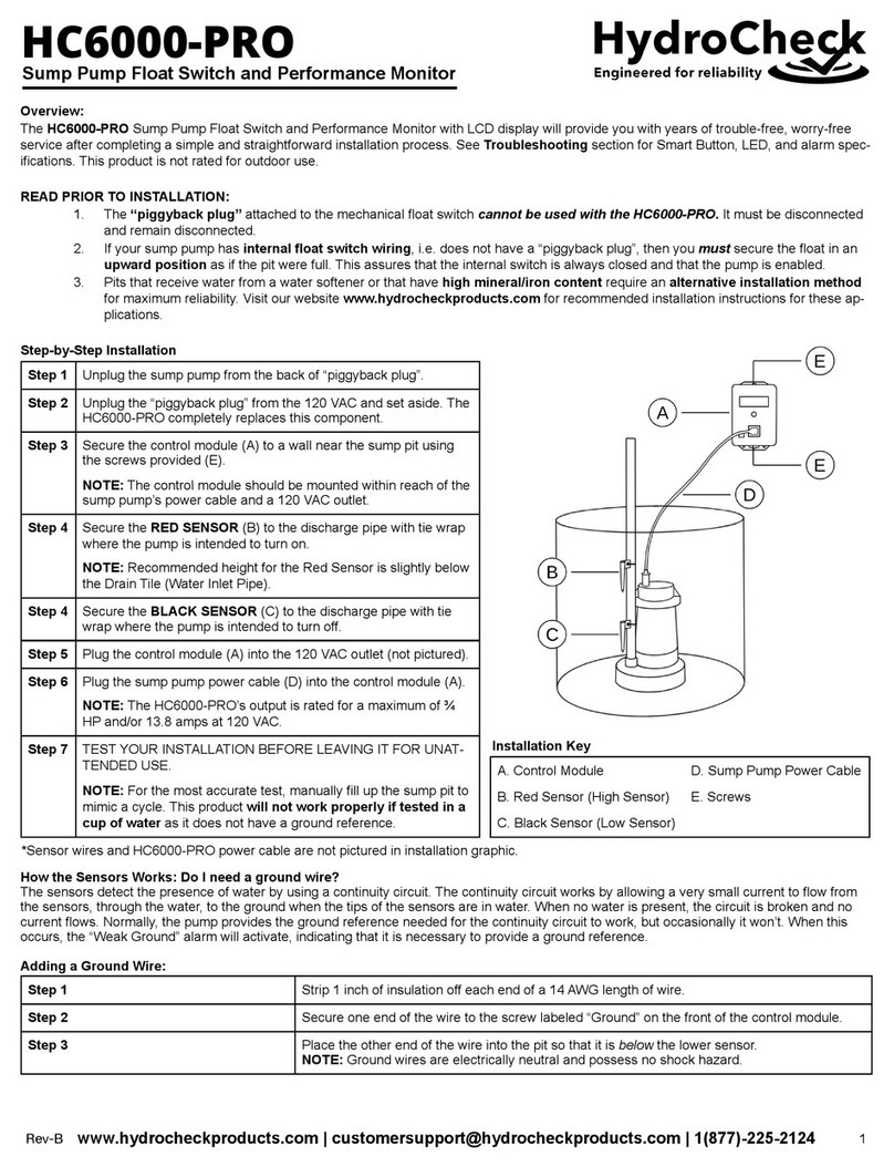
Secure the control module (A) to a wall near the sump pit using
the screws provided (E).
NOTE: The control module should be mounted within reach of the
sump pump’s power cable and a 120 VAC outlet.
Step 4
Secure the RED SENSOR (B) to the discharge pipe with tie wrap
where the pump is intended to turn on.
NOTE: Recommended height for the Red Sensor is slightly below
the Drain Tile (Water Inlet Pipe).
Step 4
Secure the BLACK SENSOR (C) to the discharge pipe with tie
wrap where the pump is intended to turn off.
Step 5
Plug the control module (A) into the 120 VAC outlet (not pictured).
Step 6
Plug the sump pump power cable (D) into the control module (A).
NOTE: The HC6000-PRO’s output is rated for a maximum of ¾
HP and/or 13.8 amps at 120 VAC.
Step 7
TEST YOUR INSTALLATION BEFORE LEAVING IT FOR UNAT-
TENDED USE.
NOTE: For the most accurate test, manually fill up the sump pit to
mimic a cycle. This product will not work properly if tested in a
cup of water as it does not have a ground reference.
Step 1
Strip 1 inch of insulation off each end of a 14 AWG length of wire.
Step 2
Secure one end of the wire to the screw labeled “Ground” on the front of the control module.
Step 3
Place the other end of the wire into the pit so that it is below the lower sensor.
NOTE: Ground wires are electrically neutral and possess no shock hazard.
!!
1
Rev-A
A. Control Module
D. Sump Pump Power Cable
B. Red Sensor (High Sensor)
E. Screws
C. Black Sensor (Low Sensor)
Installation Key
Sump Pump Float Switch and Performance Monitor
HC6000-PRO
*Sensor wires and HC6000-PRO power cable are not pictured in installation graphic.

Alarm Messages
Display Messages
Push Button Features
WARRANTY:
STAK Enterprises Inc. warrants the model HC6000-PRO to be free from defects in materials and workmanship for its normal, useful life, for a period of 5 years
from the date of purchase. STAK Enterprises Inc. makes no other express warranty for this device. No agent, representative, dealer, or employee of STAK Enter-
prises Inc. has the authority to increase or alter the obligations or limitations of the warranty. The company's obligation of this warranty shall be limited to the repair
or replacement of any part of the HC6000-PRO which is found to be defective in materials or workmanship under normal use and service during the 5 year period
of product use by original product owner commencing with the date of purchase. Owner must pay all shipping charges necessary to replace product covered by
this warranty. This warranty shall not apply to acts of God, nor shall it apply to products which, in the sole judgment of STAK Enterprises, Inc. have been subject
to negligence, abuse, accident, tampering, alteration, misapplication, or improper installation.
THE DURATION OF ANY EXPRESS OR IMPLIED WARRANTY, INCLUDING THAT OF MERCHANTABILITY OR FITNESS FOR ANY PARTICULAR PURPOS-
ES, SHALL BE LIMITED TO THE NORMAL, USEFUL LIFE OF THE PRODUCT, COMMENCING WITH THE DATE OF PURCHASE. IN NO CASE SHALL THE
COMPANY BE LIABLE FOR ANY CONSEQUENTIAL OR INCIDENTAL DAMAGES FOR BREACH OF THIS OR ANY OTHER WARRANTY, EXPRESS OR IM-
PLIED, WHATSOEVER.
Alarm Type/Display Message
Condition
High Water
Triggers after 25 seconds if the Red Sensor is still detecting water after two “air lock” attempts.
Pump Not Detected
Triggers if the switch turns the pump on, but no pump current is detected.
Auto Test No Amp
Triggers if the switch turns the pump on during an Auto Test and no pump current is detected.
Weak Ground
Triggers if water reaches the Red Sensor and the Black Sensor isn’t detecting water due to a
weak/missing ground.
Red Sensor Dirty
Triggers during an Auto Test if the switch determines that the Red Sensor should be cleaned.
Black Sensor Dirty
Triggers during an Auto Test if the switch determines that the Black Sensor should be cleaned.
Black Sensor Fail
Triggers if the Black Sensor isn’t detecting water at the start of the pump cycle.
Description
Total Cycles:
000,000,000
Total number of pump cycles since the switch was installed.
Cycles Since Reset:
000,000,000
Total number of cycles since the switch was installed or reset (See “Reset” description below).
Max. Amps: xx.x
Avg. Amps: xx.x
Max Amps = Maximum recorded pump amps since switch reset.
Avg. Amps = Average pump amps over the previous 16 pump cycles.
NOTE: Average amps data will not be displayed until the pump has run 16 cycles.
Max. Cycle: 0:00:00
Min. Cycle: 0:00:00
Maximum and minimum pump cycle time since last switch reset.
NOTE: Maximum and minimum cycle data will not be displayed until the pump has run at least one
cycle.
Fill Time/Cycle:
Last: 0:00:00
Displays the time it took to fill the pit between the last two cycles.
NOTE: Data will not be displayed until the pump has run at least one cycle.
Fill Time/Cycle:
Current: 0:00:00
Displays the time since the last cycle.
NOTE: Data will not be displayed until the pump has run at least one cycle.
Action
Response
Scrolling Function
Press the Smart Button to scroll through the different data screens.
System Test
Press and hold the Red Button. Release after 3 beeps.
Alarm Menu Access
Press and hold the Smart Button to access the Alarm Menu. Release after 3 beeps.
Press and hold the Smart Button to exit the Alarm Menu. Release after 3 beeps.
Silence Active Alarm
Press the Smart Button to silence an active alarm.
Disable Active Alarm for
24 Hours
Press and hold the Smart Button to disable an active alarm for 24 hrs.
3 beeps indicates that the alarm has been disabled.
Disable or Enable Alarms
1. Press and hold the Smart Button to access the Alarm Menu. Release after 3 beeps.
2. While the desired alarm is displayed, press the Red Button to either disable or enable that alarm.
3. Press and hold the Smart Button to exit the Alarm Menu. Release after 3 beeps.
!!
2
Rev-A
Table of contents
Other HydroCheck Water Pump manuals
Popular Water Pump manuals by other brands

VIEWEG
VIEWEG PPD-3000 operating instructions

Pontec
Pontec PondoRell 3000 UVC operating instructions

SHURflo
SHURflo 166-269 Series Technical Service

Hytorc
Hytorc HY-Ex Translation of the original operating instructions

PHCC
PHCC Pro Series Instruction manual & safety warnings

Hozelock
Hozelock 7816 instructions

Oase
Oase ProMax MudDrain 20000 operating instructions

Speck
Speck P71/250-100RDK operating instructions

Ingersoll-Rand
Ingersoll-Rand 650484-X Operator's manual

Idex
Idex VIKING PUMP 4124B Series Technical & service manual

Calpeda
Calpeda Unimat-E Series Installation, operation & maintenance instructions

LOMAC
LOMAC SUVERAIN 10FFA-A quick start guide