manuals.online logo
Brands
  1. Home
  2. •
  3. Brands
  4. •
  5. HYDROCOWL
  6. •
  7. Enclosure
  8. •
  9. HYDROCOWL SAFE-T-COVER 600DS Series User manual

HYDROCOWL SAFE-T-COVER 600DS Series User manual

The information contained herein is intended for the use of the individual(s) named above and those authorized to receive it. Dissemination, distribution
or copy of this information is strictly prohibited.
ASSEMBLY INSTRUCTIONS PLEASE READ CAREFULLY
Model No.
Inside
Dimensions
Outside
Dimensions
Recommended Concrete
Pad Dimensions
600DS Series
70"W x 128"L x 56"H
73 3/4"W x 131"L x 59 1/4"H
84"W x 142"L x 6" Thick
600TDS Series
70"W x 128"L x 64"H
73 3/4"W x 131"L x 67 1/4"H
84"W x 142"L x 6" Thick
800D Series
78"W x 124"L x 60"H
81 3/4"W x 127"L x 63 1/4"H
92"W x 138"L x 6" Thick
800DS Series
78"W x 150"L x 60"H
81 3/4"W x 153"L x 63 1/4"H
92"W x 164"L x 6" Thick
800TD Series
78"W x 124"L x 80"H
81 3/4"W x 127"L x 83 1/4"H
92"W x 138"L x 6" Thick
800TDS Series
78"W x 150"L x 80"H
81 3/4"W x 153"L x 83 1/4"H
92"W x 164"L x 6" Thick
1000D Series
90"W x 144"L x 78"H
93 3/4"W x 147"L x 81 1/4"H
104"W x 158"L x 6" Thick
1000TD Series
90"W x 144"L x 90"H
93 3/4"W x 147"L x 93 1/4"H
104"W x 158"L x 6" Thick
1. The concrete base should be 6”thick x 14”longer than enclosure ID x 14”wider than enclosure ID.
A. Mark the concrete base for the outside of the enclosure (3” wider than ID and 3” longer than ID).
2. The PVC masking film will help to protect the finish of the metal panels during installation. These
coatings should be left intact and removed only after assembly of the enclosure is complete.
The information contained herein is intended for the use of the individual(s) named above and those authorized to receive it. Dissemination, distribution
or copy of this information is strictly prohibited.
A. Stand both sets of “A1” & “A2” panels firmly together. Fasten the panels together through the holes
provided on the inside of the panels using hex headed screws. Make sure the panels are pulled tightly
together before tightening the screws. (For best results, insert a bead of silicone caulk into the inside
bend of the “A1” panel flanges.)
B. Assemble each “B-A1-A2-B” (side-end-side) assembly through the holes provided using hex headed
screws. Set them on the marked concrete base (Fig. 2). (For best results, insert a bead of silicone caulk
into the inside bend of the “A#” panel corners.)
3. Inspect the alignment of the “C” (access) panels during the assembly process. Verify that their
removal and replacement allows adequate space and positioning within the openings and with the
adjacent panels prior to attaching any bracket to the concrete.
NOTE: model sizes and configurations vary, see the chart.
4. Set a “D1” (roof) panel on a “B-A1-A2-B” (side-end-side) assembly using the “C” (access) panels for
temporary roof support if needed. Fasten the “D1” (roof) panel to the “B-A1-A2-B” (side-end-side)
assembly through the holes provided (Fig. 1) using three (3) hex headed screws.
A. Insert an Inside Roof Clip into the “D1” (roof) panel at the “A2” panel stud (Fig. 1C). Attach the clip to
the “A2” panel stud as shown using one (1) hex headed screw.
B. Repeat 4 and 4A for the other “D1” (roof) panel and “B-A1-A2-B”(side-end-side) assembly.
The information contained herein is intended for the use of the individual(s) named above and those authorized to receive it. Dissemination, distribution
or copy of this information is strictly prohibited.
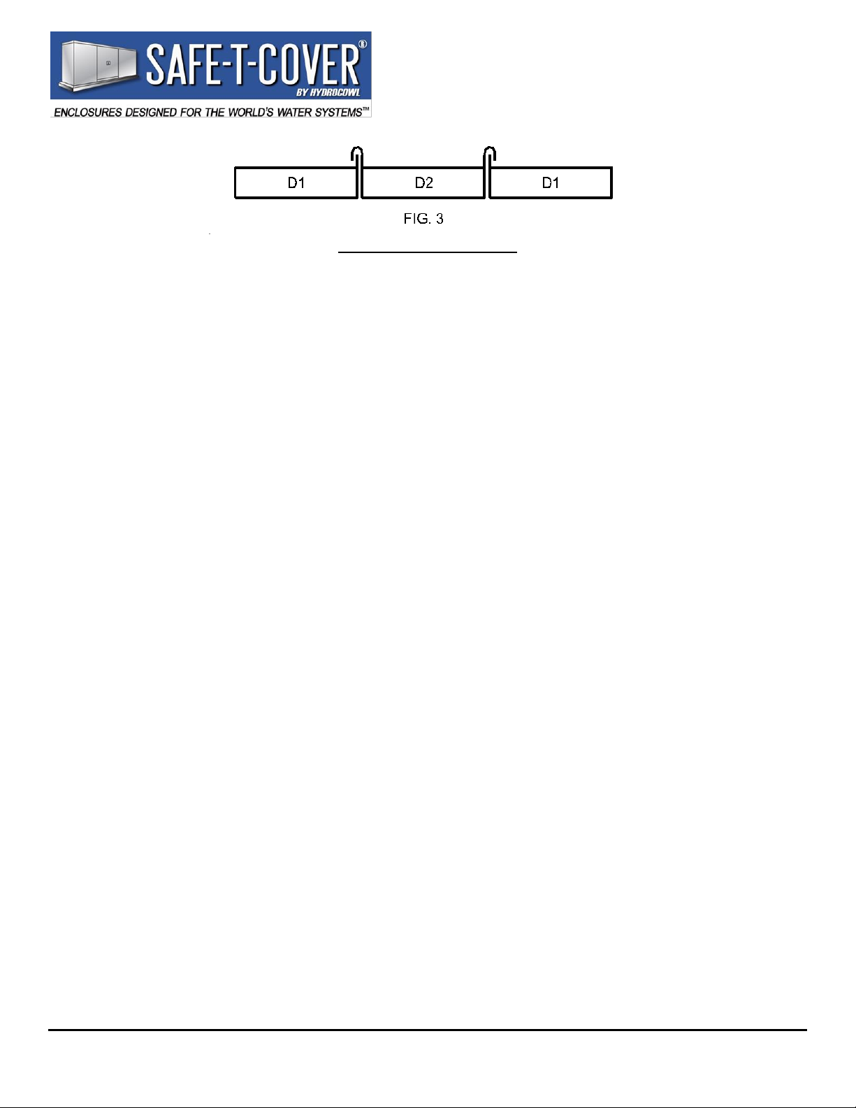
Side View of Roof Panels
5. Set the “C” (access) panels and the “F” (support) posts in place with about a 3/16” gap on each side of
the “C” panels as the roof is assembled.
A. Position the “D2” (roof) middle panel (Fig. 3) between the “D1” (roof) end panels and set it in place.
On the inside, place Inner Roof Connection Brackets under the “D1-D2” wooden rafter panel
connections. Fasten the Inner Roof Connection Brackets into place (Fig. 1E) using hex headed screws.
6. Attach an Outside Corner Anchoring Bracket to an “A#-B” (corner) assembly (Fig. 1A) using two (2)
hex headed screws. Fasten the bracket to the concrete using one (1) anchor. Fasten one (1) Outside
Corner Anchoring Bracket at both “A#-B” (corner) assemblies on one side.
A. Attach Inside Anchoring Brackets to the “B” (side) panels at the bottom, inside at the concrete (Fig. 1B)
using two (2) hex headed screws per bracket. Fasten them to the concrete using one (1) anchor per
bracket. Fasten Inside Anchoring Brackets to the “B” panels and concrete along one side of the
enclosure.
B. Insert Inside Roof Clips into the “D1” (roof) panels at the “B” (side) panel studs (Fig. 1C). Attach the
clips to the “B” panels using one (1) hex headed screw per clip. Fasten Inside Roof Clips to the “B” and
“D1” panels along one side of the enclosure.
C. Repeat Steps 6, 6A and 6B on the other side and end of the enclosure.
7. With the “F” (support) posts properly positioned in the spaces between the “C” (access) panels (see
Step 5), install Inside Anchoring Brackets (Fig. 1B) at the bottom of the “F” (support) posts.
A. Attach the “F” (support) posts studs to the tabs in the middle of the “D2” (roof) panel using hex headed
screws. If no tabs are provided on the “D2” (roof) panel, use the remaining Inside Roof Clips to secure
the tops of the “F” posts to the “D2” (roof) panel.
8. Install Roof Cover Plates on the “D1-D2” roof seams (Fig. 1D) using two (2) hex headed screws per
plate.
9. Provide a ground-fault interrupter device in all electrical circuits per all applicable codes. Install the
heater(s) as per the manufacturer’s instructions and governing local and national codes.
10. For maximum protection, it is suggested that the area between the bottom of the enclosure and the
concrete base should be caulked except for the “C” panels. DO NOT CAULK THE BOTTOM OF
THE “C” PANELS.
11. REMOVE THE PVC MASKING FILM IMMEDIATELY AFTER INSTALLATION. If the panels
get wet with the masking film in place, water will irreversibly stain the panels. Summertime heat will
bake the masking film onto the panels.
The information contained herein is intended for the use of the individual(s) named above and those authorized to receive it. Dissemination, distribution
or copy of this information is strictly prohibited.
Model No. 600DS-AL Series
Model No. 600TDS-AL Series
Model No. 800D-AL Series
Model No. 800DS-AL Series
Model No. 800TD-AL Series
Model No. 800TDS-AL Series
Model No. 1000D-AL Series
Model No. 1000TD-AL Series
CONTENTS
1. Your assembly should include
A. 2- “A1” (end) Panels
B. 2- “A2” (end) Panels
C. 4- “B” (side) Panels with Louvers
D. 4- “C”& “Cw/d” (removable access) Panels
E. 2- “D1” (roof) Panels
F. 1- “D2” (roof) Panel
G. 2- “F” (support) Posts
H. 4- Outside Corner Anchoring Brackets (1 ½”x 1 ½”)
I. 8- Inside Anchoring Brackets (3”x 3”)
J. 8- Inside Roof Clips (1000D-AL & 1000TD-AL use Inside Roof Clips - LARGE)
K. 4- Roof Cover Plates (1000D-AL & 1000TD-AL use Roof Cover Plates - LARGE)
L. 2- Inner Roof Connection Brackets
M. 1- Package of Anchors
N. 1- Package of Hex headed screws
O. 1- Masonry Bit
P. 1- Magnetic Chuck
2. Tools you will need
A. Hammer
B. Drill
C. ¾”Wrench

This manual suits for next models

15

Other HYDROCOWL Enclosure manuals

HYDROCOWL SAFE-T-COVER 1000TDS-AL User manual

HYDROCOWL

HYDROCOWL SAFE-T-COVER 1000TDS-AL User manual

HYDROCOWL Safe-T-Cover 800S Series User manual

HYDROCOWL

HYDROCOWL Safe-T-Cover 800S Series User manual

HYDROCOWL Safe-T-Cover 300 Series User manual

HYDROCOWL

HYDROCOWL Safe-T-Cover 300 Series User manual

HYDROCOWL SAFE-T-COVER 1000DS Series User manual

HYDROCOWL

HYDROCOWL SAFE-T-COVER 1000DS Series User manual

HYDROCOWL Safe-t-Cover 300DS Series User manual

HYDROCOWL

HYDROCOWL Safe-t-Cover 300DS Series User manual

HYDROCOWL SAFE-T-COVER 600TD Series User manual

HYDROCOWL

HYDROCOWL SAFE-T-COVER 600TD Series User manual

HYDROCOWL Safe-T-Cover 800 Series User manual

HYDROCOWL

HYDROCOWL Safe-T-Cover 800 Series User manual

Popular Enclosure manuals by other brands

Gembird EE2-U3S-3 user manual

Gembird

Gembird EE2-U3S-3 user manual

ENERMAX EMK3101 user manual

ENERMAX

ENERMAX EMK3101 user manual

Sharkoon Nightfall U3 manual

Sharkoon

Sharkoon Nightfall U3 manual

Conceptronic CHD3DUSB3 quick guide

Conceptronic

Conceptronic CHD3DUSB3 quick guide

Zahl RACK 500 DUAL manual

Zahl

Zahl RACK 500 DUAL manual

Pulsar AWO 350 Assembly instructions

Pulsar

Pulsar AWO 350 Assembly instructions

GRAUPNER Li-Po SAFE Bag Use and safety instructions

GRAUPNER

GRAUPNER Li-Po SAFE Bag Use and safety instructions

Pulsar 7/TRZ40/SATEL/GRADE 3 Assembly instructions

Pulsar

Pulsar 7/TRZ40/SATEL/GRADE 3 Assembly instructions

Gewiss 40-CD Series Assembly instructions

Gewiss

Gewiss 40-CD Series Assembly instructions

Akasa Pi-4Pro installation manual

Akasa

Akasa Pi-4Pro installation manual

QNAP TR-004-US user guide

QNAP

QNAP TR-004-US user guide

SilentiumPC Armis AR5 quick start guide

SilentiumPC

SilentiumPC Armis AR5 quick start guide

National Instruments NI 9925 installation guide

National Instruments

National Instruments NI 9925 installation guide

Pyle PLBP102 Specifications

Pyle

Pyle PLBP102 Specifications

Cochlear Aqua+ user guide

Cochlear

Cochlear Aqua+ user guide

Cooler Master HCRAFT 250 installation guide

Cooler Master

Cooler Master HCRAFT 250 installation guide

Joy-it RB-AlucaseP4+08 manual

Joy-it

Joy-it RB-AlucaseP4+08 manual

Trixie 62404 Assembling Instruction

Trixie

Trixie 62404 Assembling Instruction

manuals.online logo
manuals.online logoBrands
  • About & Mission
  • Contact us
  • Privacy Policy
  • Terms and Conditions

Copyright 2025 Manuals.Online. All Rights Reserved.