HYDROLOGICAL SERVICES HYC 230 User manual

Hydra-Pulse HYC Level Radar Manual
HYC 230 Radar Sensor for continuous level measurement
SDI-12 Version

2
Product description
Hydra-Pulse HYC 230 • SDI-12
Product description
Configuration
The scope of delivery encompasses:
•Radar sensor
•Counter nut G1 1)
•Information sheet " Documents and software" with:
– Instrument serial number
– QR code with link for direct scanning
•Information sheet " PINs and Codes" (with Bluetooth versions)
with:
– Bluetooth access code
•Information sheet " Access protection" (with Bluetooth versions)
with:
– Bluetooth access code
– Emergency Bluetooth unlock code
– Emergency device code
The further scope of delivery encompasses:
•Documentation
– Ex-specic"Safety instructions" (with Ex versions)
– Radio licenses
– Ifnecessary,furthercerticates
Note:
Optional instrument features are also described in this operating
instructions manual.The respective scope of delivery results from the
orderspecication.
This operating instructions manual applies to the following instrument
versions:
•Hardware version from 1.0.0
•Software version from 1.2.0
Scope of delivery
Scope of this operating
instructions
1) With G thread

3
Hydra-Pulse HYC 230 • SDI-12
Principle of operation
Hydra-Pulse HYC 230 is a radar sensor for non-contact, continuous
level measurement. It is suitable for liquids and solids in practically all
industries.
The device is designed for connection to data loggers with SDI-12
interface, making it particularly suitable for battery-powered applica-
tions requiring low power consumption.
The Hydra-Pulse HYC 230 can be operated at any data logger with
SDI-12 interface. The sensors are powered via the +12 V line of the
three-wire connection cable.
The instrument emits a continuous, frequency-modulated radar signal
throughitsantenna.Theemittedsignalisreflectedbythemedium
andreceivedbytheantennaasanechowithmodifiedfrequency.The
frequency change is proportional to the distance and is converted
into the level.
Adjustment
The optionally integrated Bluetooth module enables a wireless
adjust-ment of Hydra-Pulse HYC 230 via standard adjustment
devices:
•Smartphone/tablet (iOS or Android operating system)
•PC/notebook with Bluetooth USB adapter (Windows operating
system)
13
2
The SDI-12 data communication is controlled by commands from
the SDI-12 data logger via the signal cable.
Application area
Power supply and signal
processing
Functional principle
Wireless adjustment
Adjustment via the signal
cable
Download our easy to use App for your phone or tablet.
Search for "Wireless Device Configurator" at the App Store
or on Google Play.
Fig. 3: Wireless connection to standard operating devices with integrated
Bluetooth LE
1 Sensor
2 Smartphone/Tablet
3 PC/Notebook

4
Product description
Hydra-Pulse HYC 230 • SDI-12
12
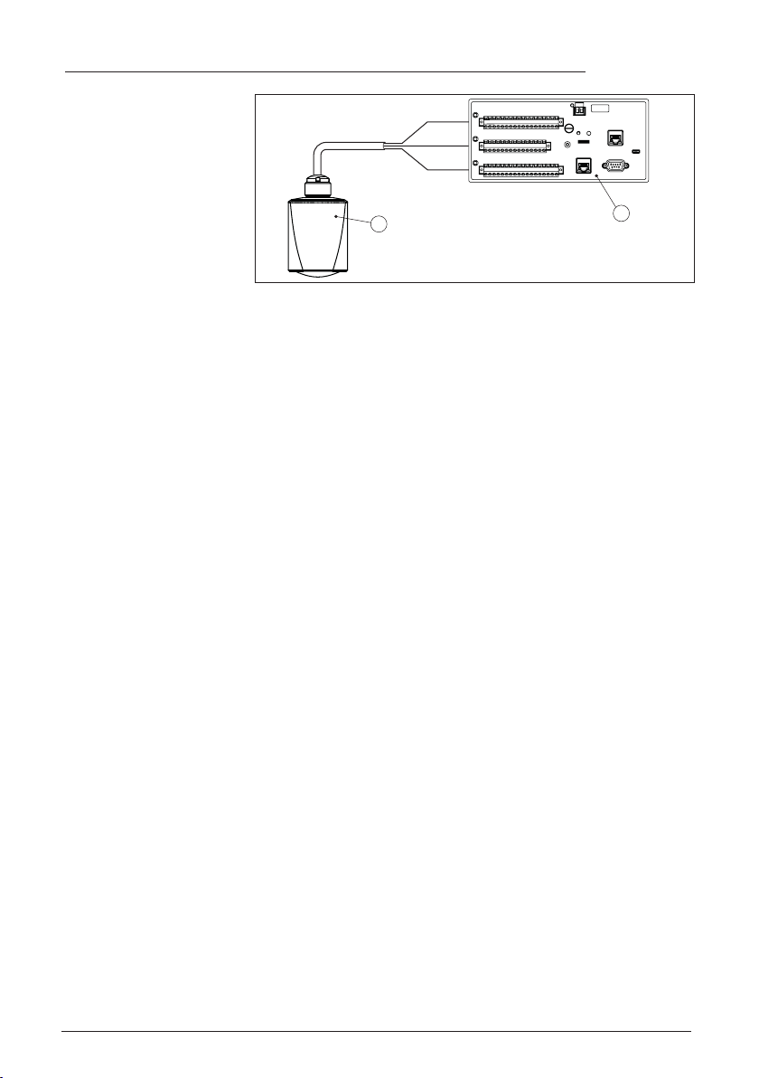
Fig. 4: Connection of Hydra-Pulse HYC 230 SDI-12 to the data logge
1 Sensor
2 Data logger
Packaging, transport and storage
Your instrument was protected by packaging during transport. Its
capacity to handle normal loads during transport is assured by a test
based on ISO 4180.
The packaging consists of environment-friendly, recyclable card-
board. For special versions, PE foam or PE foil is also used. Dispose
of the packaging material via specialised recycling companies.
Transport must be carried out in due consideration of the notes on the
transport packaging. Nonobservance of these instructions can cause
damage to the device.
The delivery must be checked for completeness and possible transit
damage immediately at receipt. Ascertained transit damage or con-
cealed defects must be appropriately dealt with.
Up to the time of installation, the packages must be left closed and
stored according to the orientation and storage markings on the
outside.
Unless otherwise indicated, the packages must be stored only under
the following conditions:
•Not in the open
•Dry and dust free
•Not exposed to corrosive media
•Protected against solar radiation
•Avoiding mechanical shock and vibration
•Storage and transport temperature see chapter " Supplement -
Technical data - Ambient conditions"
•Relative humidity 20 … 85 %
Accessories
Screwedangesareavailableindierentversionsaccordingtothe
following standards: DIN 2501, EN 1092-1, BS 10, A SME B 16.5,
JIS B 2210-1984, GOST 12821-80.
Packaging
Transport
Transport inspection
Storage
Storage and transport
temperature
Flanges

5
Product description
Hydra-Pulse HYC 230 • SDI-12
Welded sockets are used to connect the devices to the process.
Threaded adapters enable simple adaptation of devices with stand-
ardthreadedttings,e.g.toprocess-sidehygieneconnections.
The mounting accessories are used for stable mounting of the device
at the measuring point. The parts are available in various versions and
sizes.
Welded sockets and
adapters
Mounting strap

6
Mounting
Hydra-Pulse HYC 230 • SDI-12
Mounting
General instructions
The instrument is suitable for standard and extended ambient condi-
tions acc. to DIN/EN/IEC/ANSI/ISA/UL/CSA 61010-1. It can be used
indoors as well as outdoors.
Note:
For safety reasons, the instrument must only be operated within the
permissibleprocessconditions.Youcannddetailedinformationon
the process conditions in chapter " Technical data" of the operating
instructions or on the type label.
Hence make sure before mounting that all parts of the instrument ex-
posed to the process are suitable for the existing process conditions.
These are mainly:
•Active measuring component
•Processtting
•Process seal
Process conditions in particular are:
•Process pressure
•Process temperature
•Chemical properties of the medium
•Abrasionandmechanicalinuences
Mounting versions
For the wall mounting, a mounting bracket with opening for thread G1
is recommended.The mounting of the device in the bracket is carried
out via the supplied G1 counter nut of plastic. Take note of chapter "
Mounting instructions" for the recommended distance to the wall.
> 200 mm
(7.87
")
Fig. 5: Mounting via a mounting bracket
Ambient conditions
Process conditions
Mounting bracket

7
Mounting
Hydra-Pulse HYC 230 • SDI-12
Mounting instructions
Radar sensors for level measurement emit electromagnetic waves.
The polarization is the direction of the electrical component of these
waves.
The position of the polarisation is in the middle of the type label on the
instrument.
1
Fig. 6: Position of the polarisation
1 Middle of the type label
Note:
When the device is rotated, the direction of polarization changes and
hencetheinuenceofthefalseechoonthemeasuredvalue.Please
keep this in mind when mounting or making changes later.
Mount the device at a position that is at least 200 mm (7.874 in) away
from a wall or structural parts (see illustrations above).
If you cannot maintain this distance, you should carry out a false
signal suppression during setup.This applies particularly if buildup
on the wall or structural parts is to be expected. In such cases, we
recommend repeating the false signal suppression at a later date with
existing buildup.
The centre of the antenna lens is the beginning of the measuring
range and at the same time the reference plane for the min./max.
adjustment, see following diagram:
1
Fig. 7: Reference plane
1 Reference plane
Donotmounttheinstrumentsinorabovethellingstream.Makesure
thatyoudetectthemediumsurface,nottheinowingproduct.
Polarisation
Installation position
Reference plane
Inowingmedium

8
Mounting
Hydra-Pulse HYC 230 • SDI-12
Measurement setups - Gauge
In general, the following must be observed while mounting the sensor:
•Mounting on solid bracket or mounting bracket
•High or low water for mounting position
•Measurementonwatersurfaceasataspossibleincalmarea
•Minimum distance to the max. water level
The following examples serve as an overview for gauge measure-
ment.
Fig. 14: Gauge measurement river, sensor mounting on bridge pier
River level
Fig. 15: Gauge measurement dam, sensor mounting on bracket
Dam gauge

9
Mounting
Hydra-Pulse HYC 230 • SDI-12
Fig. 16: Gauge measurement deep well, sensor mounting on lid
Deep well level

10
Connecting to power supply
Hydra-Pulse HYC 230 • SDI-12
Connecting to power supply
Preparing the connection
Always keep in mind the following safety instructions:
•Carryoutelectricalconnectionbytrained,qualiedpersonnel
authorised by the plant operator
Warning:
Only connect or disconnect in de-energized state.
The device is supplied with power via an SDI-12 datalogger.
Note:
Power the instrument via an energy-limited circuit (power max. 100 W)
acc. to IEC 61010-1, e.g.
•Class 2 power supply unit (acc. to UL1310)
•SELV power supply unit (safety extra-low voltage) with suitable
internal or external limitation of the output current
Thedataforpowersupplyarespeciedinchapter"Technical data".
Thedeviceissuppliedwithaxedconnectedcable.Ifanextensionis
required, a standard three-wire cable can be used.
If electromagnetic interference is expected which is above the test
values of EN 61326-1 for industrial areas, shielded cable should be
used.
We recommend to connect the cable screening to ground potential at
one end on the supply side when using shielded cable.
Wiring plan
1
2
3
4
Fig. 19: Wire assignment in permanently connected connection cable
Wire colour Function Polarity
1 Brown Voltage supply Plus (+)
2 Blue Voltage supply Minus (-)
3 White SDI data Plus (+)
4 Shielding
Safety instructions
Voltage supply
Connection cable
Cable screening and
grounding
Wire assignment, con-
nection cable

11
Connecting to power supply
Hydra-Pulse HYC 230 • SDI-12
Switch-on phase
After connection to the power supply, the device carries out a self-
test.
Note:
No SDI-12 commands are answered during this self-test
After the self-test, the standard SDI-12 communication is used.
Transmitted values take settings into account that have already been
carried out, e.g. default setting.

12
Access protection
Hydra-Pulse HYC 230 • SDI-12
Access protection
Bluetooth radio interface
Devices with a Bluetooth radio interface are protected against un-
wanted access from outside.This means that only authorized persons
can receive measured and status values and change device settings
via this interface.
A Bluetooth access code is required to establish Bluetooth com-
munication via the adjustment tool (smartphone/tablet/notebook).
This code must be entered once when Bluetooth communication is
establishedforthersttimeintheadjustmenttool.Itisthenstoredin
the adjustment tool and does not have to be entered again.
The Bluetooth access code is individual for each device. It is printed
on the device housing and is also supplied with the device in the infor-
mation sheet " PINs and Codes". It can be changed by the user after
therstconnectionhasbeenestablished.IftheBluetoothaccess
code has not been entered correctly, a new entry can only be made
after a waiting period has elapsed.The waiting time increases with
each additional incorrect entry.
The emergency Bluetooth access code enables Bluetooth communi-
cation to be established in the event that the Bluetooth access code
is no longer known. It can't be changed.The emergency Bluetooth
access code can be found in information sheet " Access protection".
If this document is lost, the emergency Bluetooth access code can
be retrieved from your personal contact person after legitimation.
The storage and transmission of Bluetooth access codes is always
encrypted (SHA 256 algorithm).
Protection of the parameterization
The settings (parameters) of the device can be protected against un-
wanted changes. The parameter protection is deactivated on delivery,
all settings can be made.
To protect the parameterization, the device can be locked by the user
with the aid of a freely selectable device code. The settings (param-
eters) can then only be read out, but not changed.The device code
is also stored in the adjustment tool. However, unlike the Bluetooth
access code, it must be re-entered for each unlock.When using the
adjustment app or DTM, the stored device code is then suggested to
the user for unlocking.
The emergency device code allows unlocking the device in case the
device code is no longer known. It can't be changed. The emergency
device code can also be found on the supplied information sheet " Ac-
cess protection". If this document is lost, the emergency device code
can be retrieved from your personal contact person after legitimation.
The storage and transmission of the device codes is always encrypt-
ed (SHA 256 algorithm).
Bluetooth access code
Emergency Bluetooth
unlock code
Device code
Emergency device code

13
Setup with smartphone/tablet (Bluetooth)
Hydra-Pulse HYC 230 • SDI-12
Setup with smartphone/tablet (Bluetooth)
Preparations
Make sure that your smartphone/tablet meets the following system
requirements:
•Operating system: iOS 8 or newer
•Operating system: Android 5.1 or newer
•Bluetooth 4.0 LE or newer
Download the Wireless Device Configurator App from the " Apple
App Store", " Google Play Store" to your smartphone or tablet.
Connecting
Start the adjustment app and select the function " Setup".The smart-
phone/tablet searches automatically for Bluetooth-capable instru-
ments in the area.
The message " Connecting …" is displayed.
The devices found are listed and the search is automatically contin-
ued.
Select the requested instrument in the device list.
Whenestablishingtheconnectionforthefirsttime,theoperatingtool
andthesensormustauthenticateeachother.Afterthefirstcorrect
authentication, each subsequent connection is made without a new
authentication query.
For authentication, enter the 6-digit Bluetooth access code in the
nextmenuwindow.Youcanfindthecodeontheoutsideofthe
devicehousing and on the information sheet.
Fig. 20: Enter Bluetooth access code
Note:
If an incorrect code is entered, the code can only be entered again
after a delay time. This time gets longer after each incorrect entry.
The message " Waiting for authentication" is displayed on the smart-
phone/tablet.
After connection, the sensor adjustment menu is displayed on the
respective adjustment tool.
System requirements
Connecting
Authenticate
Enter Bluetooth access
code
Connected

14
Setup with smartphone/tablet (Bluetooth)
Hydra-Pulse HYC 230 • SDI-12
If the Bluetooth connection is interrupted, e.g. due to a too large
distance between the two devices, this is displayed on the adjustment
tool. The message disappears when the connection is restored.
Parameter adjustment of the device is only possible if the parameter
protection is deactivated. When delivered, parameter protection is
deactivated by default and can be activated at any time.
It is recommended to enter a personal 6-digit device code.To do this,
go to menu " Extended functions", " Access protection", menu item "
Protection of the parameter adjustment".
Parameter adjustment
The sensor adjustment menu is divided into two areas, which are
arranged next to each other or one below the other, depending on the
adjustment tool.
•Navigation section
•Menu item display
The selected menu item can be recognized by the colour change.
Fig. 21: Example of an app view - Setup measured values
Entertherequestedparametersandconrmviathekeyboardorthe
editingeld.Thesettingsarethenactiveinthesensor.
Close the app to terminate connection.
Change device code
Enter parameters

15
Adjustment menu
Hydra-Pulse HYC 230 • SDI-12
Adjustment menu
Menu overview
Device information Actual measured values Device status
Device name, software ver-
sion, serial number
Percent,llingheight,distance,measurementreliability,
electronics temperature, meas. rate etc.
OK, error indication
Menu item Selection Basic settings
Measurement loop name Alphanumeric characters Sensor
Application liquid Storage tank, agitator tank, dosing tank, pumping sta-
tion/pumpshaft,rainoverowbasin,tank/collection
basin, plastic tank (measurement through tank top), mo-
bileplastictank(IBC),levelmeasurementinwaters,ow
measurementume/overow,demonstration
Storage tank
Application bulk solid Silo (slim and high), bunker (large volume), stockpile
(pointmeasurement/proledetection),crusher,demon-
stration
Silo (slender and
high)
Units Distance unit of the device
Temperature unit of the instrument
Distance in m
Temperature in °C
Adjustment Max. adjustment (distance A)
Min. adjustment (distance B)
Max. adjustment
15,000 m
Min. adjustment
0,000 m
Menu item Selection Basic settings
Damping Integration time 0 s
Linearisation Linearization type Linear
Scaling Scaling size
Scaling unit
Scaling format
100 % correspond to
0 % correspond to
Volume
l
100 l
0 l
Display Menu language
Displayed value
Backlight
-
Distance
On
Access protection Bluetooth access code -
Protection of the parameterization Deactivated
False signal suppression Create new, extend, delete, manual entry -
Sounded distance to the medium 0 m
Reset Delivery status, basic settings -
Start image (app)
Main menu
Extended functions

16
Adjustment menu
Hydra-Pulse HYC 230 • SDI-12
Menu item Selection Basic settings
Mode Mode 1: EU, Albania, Andorra, Azerbaijan, Australia, Be-
larus, Bosnia and Herzegovina, Canada, Liechtenstein,
Moldavia, Monaco, Montenegro, New Zealand, Northern
Macedonia, Norway, San Marino, Saudi Arabia, Serbia,
Switzerland, Turkey, Ukraine, United Kingdom, USA
Mode 2: South Korea, Taiwan,Thailand
Mode of operation 3: India, Malaysia, South Africa
Mode of operation 4: Russia, Kazakhstan
Mode 1
Status signals Function check
Maintenance required
Outofspecication
On
O
O
Menu item Selection Basic settings
Status Device status
Parametermodicationcounter
Measured value status
Status output
Status additional measured values
-
Echo curve Indication of echo curve -
Peak value indicator Pointer function distance, measurement reliability, meas.
rate, electronic temperature
-
Measured values Measured values
Additional measured values
Outputs
-
Sensor information Device name, serial number, hardware/software version,
device revision, factory calibration date
-
Sensor characteristics Sensor features from order text -
Simulation Measured value
Simulation value
-
Measured value memory
(DTM)
Indication measured value memory from DTM
Description of the applications
This menu item enables you to optimally adapt the sensor to the ap-
plication, the place of use and the measuring conditions.The adjust-
ment possibilities depend on the selection made under " Medium", "
Liquid" or " Bulk solid".
The vessels as well as the measuring and process conditions are
described in the following as an overview.
With " Liquid", the applications are based on the following features,
to which the measuring characteristic of the sensor is adjusted in
particular:
Diagnostics
Application
Application - liquid

17
Adjustment menu
Hydra-Pulse HYC 230 • SDI-12
Storage tank
•Vessel:
– Large volume
– Upright cylindrical, horizontal round
•Process/measurement conditions:
– Slowllingandemptying
– Smooth medium surface
– Multiplereectionsfromdishedvesselceiling
– Condensation
Pumping station/Pump shaft
•Process/measurement conditions:
– Partly strongly agitated surface
– Installations such as pumps and ladders
– Multiplereectionsthroughatvesselceiling
– Dirt and grease deposits on shaft wall and sensor
– Condensation on the sensor
•Further recommendations
– False signal suppression via adjustment app or PACTware/DTM
Overowbasin
•Vessel
– Large volume
– Partly installed underground
•Process/measurement conditions:
– Partly strongly agitated surface
– Multiplereectionsthroughatvesselceiling
– Condensation, dirt deposits on the sensor
– Flooding of the sensor antenna
Gauge measurement in waters
•Process/measurement conditions:
– Slow gauge change
– Extreme damping of output signal in case of wave generation
– Ice and condensation on the antenna possible
– Floating debris sporadically on the water surface
Plastic tank (measurement through the vessel top)
•Process/measurement conditions:
– Measurement through the tank top, if appropriate to the applica-
tion
– Condensation on the plastic ceiling
– In outdoor facilities, water and snow on vessel top possible
•Further recommendations
– With measurement through the tank top false signal suppres-
sion via adjustment app or PACTware/DTM
– When measuring through the tank top in outdoor areas protec-
tive roof for the measuring point

18
Diagnostics and servicing
Hydra-Pulse HYC 230 • SDI-12
Diagnostics and servicing
Maintenance
If the device is used properly, no special maintenance is required in
normal operation.
Insomeapplications,buildupontheantennasystemcaninuence
the measuring result. Depending on the sensor and application, take
measures to avoid heavy soiling of the antenna system. If necessary,
clean the antenna system in certain intervals.
The cleaning helps that the type label and markings on the instrument
are visible.
Take note of the following:
•Use only cleaning agents which do not corrode the housings, type
label and seals
•Use only cleaning methods corresponding to the housing protec-
tion rating
Rectify faults
The operator of the system is responsible for taking suitable meas-
ures to rectify faults.
Thedeviceoersmaximumreliability.Nevertheless,faultscanoccur
during operation.These may be caused by the following, e.g.:
•Sensor
•Process
•Voltage supply
•Signal processing
Therstmeasuresare:
•Evaluation of fault messages
•Checking the output signal
•Treatment of measurement errors
A smartphone/tablet with the adjustment app or a PC/notebook with
thesoftwarePACTwareandthesuitableDTMoeryoufurthercom-
prehensive diagnostic possibilities. In many cases, the causes can be
determined in this way and the faults eliminated.
Depending on the reason for the fault and the measures taken, the
steps described in chapter " Setup" must be carried out again or must
be checked for plausibility and completeness.
Should these measures not be successful, please call in urgent cases
the VEGA service hotline under the phone no. +49 1805 858550.
The hotline is also available outside normal working hours, seven
days a week around the clock.
Maintenance
Precaution measures
against buildup
Cleaning
Reaction when malfunc-
tion occurs
Causes of malfunction
Faultrectication
Reaction after fault recti-
cation
24 hour service hotline

19
Diagnostics and servicing
Hydra-Pulse HYC 230 • SDI-12
Sinceweoerthisserviceworldwide,thesupportisprovidedin
English.The service itself is free of charge, the only costs involved are
the normal call charges.
Status messages according to NE 107
The instrument features self-monitoring and diagnostics according
to NE 107 and VDI/VDE 2650. In addition to the status messages in
the following tables there are more detailed error messages available
under the menu item " Diagnostics" via the respective adjustment
module.
The status messages are divided into the following categories:
•Failure
•Function check
•Outofspecication
•Maintenance required
and explained by pictographs:
41 2 3
Fig. 24: Pictographs of the status messages
1 Failure - red
2 Out of specication - yellow
3 Function check - orange
4 Maintenance required - blue
Failure: Due to a malfunction in the instrument, a fault message is
output.
This status message is always active. It cannot be deactivated by the
user.
Function check: The instrument is being worked on, the measured
value is temporarily invalid (for example during simulation).
This status message is inactive by default.
Outofspecication: The measured value is unreliable because an
instrumentspecicationwasexceeded(e.g.electronicstemperature).
This status message is inactive by default.
Maintenance required:Duetoexternalinuences,theinstrument
functionislimited.Themeasurementisaected,butthemeasured
value is still valid. Plan in maintenance for the instrument because a
failure is expected in the near future (e.g. due to buildup).
This status message is inactive by default.
Status messages

20
Diagnostics and servicing
Hydra-Pulse HYC 230 • SDI-12
Code
Text message
Cause Rectication
F013
no measured value
available
No measured value in the switch-on
phase or during operation
Sensor tilted
Check or correct installation and/or pa-
rameter settings
Clean the antenna system
F017
Adjustment span too
small
Adjustmentnotwithinspecication Change adjustment according to the limit
values(dierencebetweenmin.andmax.
≥10mm)
F025
Error in the lineariza-
tion table
Index markers are not continuously rising,
for example illogical value pairs
Check linearization table
Delete table/Create new
F036
No operable software
Checksum error if software update failed
or aborted
Repeat software update
Send instrument for repair
F040
Error in the electronics
Limit value exceeded in signal processing
Hardware error
Restart instrument
Send instrument for repair
F080
General software error
General software error Restart instrument
F105
Determine measured
value
The instrument is still in the switch-on
phase, the measured value could not yet
be determined
Wait for the end of the switch-on phase
Duration up to 3 minutes depending on
the measurement environment and pa-
rameter settings
F260
Error in the calibration
Checksum error in the calibration values
Error in the EEPROM
Send instrument for repair
F261
Error in the instrument
settings
Error during setup
False signal suppression faulty
Error when carrying out a reset
Repeat setup
Carry out a reset
F265
Measurement function
disturbed
Program sequence of the measuring func-
tion disturbed
Device restarts automatically
Code
Text message
Cause Rectication
C700
Simulation active
A simulation is active Finish simulation
Wait for the automatic end after 60 mins.
Code
Text message
Cause Rectication
S600
Impermissible electron-
ics temperature
Temperature of the electronics in the non-
speciedrange
Check ambient temperature
Insulate electronics
Failure
Function check
Outofspecication
Table of contents
Popular Radar manuals by other brands

Blackbe;rry
Blackbe;rry Radar R2 installation guide

Endress+Hauser
Endress+Hauser Micropilot FMR63B Brief operating instructions

Endress+Hauser
Endress+Hauser PROFIBUS PA Levelflex FMP50 Brief operating instructions

Endress+Hauser
Endress+Hauser HART Micropilot S FMR533 Brief operating instructions

Decatur
Decatur DragonEye Compact user manual

Radenso
Radenso RC M user manual

Endress+Hauser
Endress+Hauser Levelflex FMP56 technical information

ATS
ATS Axsis SC-300H Operation and reference manual

Siemens
Siemens SITRANS LG270 operating instructions

Furuno
Furuno FAR-3320SW installation manual

Ametek
Ametek DR22X0 Series Installation and operating instructions

Radarsign
Radarsign TC-400 installation manual