HydroPoint WaterCompass FM300 User manual

Introduction
This document covers installation for
the WC-FM300-US-OD Ultrasonic Flow
Monitors for pipe sizes of 2 1/2" and 3".
The WaterCompass FM300 Ultrasonic Flow
Monitor is a customized product made up of an
integrated WT2W-H20 Flow Decoder, a clamp-
on flow monitor and a 30 V power supply.
The monitor sends real-time flow data to the
WaterCompass Data Collector that is viewed from
the WaterCompass dashboard. Hourly summation
of flow data is stored for analysis and reporting.
Before you begin, review the safety precautions
at the end of this installation guide.
Pre-Configured Settings
To ensure accuracy, the Flow Monitor will be
pre-configured with the following settings:
• Pipe size (varies)
• Pipe type (varies)
• Flow direction (right)
• K-value (60.1)
If the values relating to pipe size, K-value, flow
direction and pipe size have to be changed
for any reason, please contact Customer
Support for additional assistance.
Contact Information:
WaterCompass Customer Support
800-362-8774
support@hydropoint.com
1800 362 8774 | hydropoint.com | [email protected]
WaterCompass FM300 Ultrasonic Flow Monitor OD
Installation Instructions
WC-FM300-US-250-OD, WC-FM300-US-300-OD
Materials Provided
• WaterCompass Data Collector
• WaterCompass Flow Monitor w/integrated flow decoder
• 30 V dc power supply
• 4 wire nuts
Equipment Needed
• Caliper
• Philips head screwdriver with long shaft
• Torx screwdriver (for pipes larger than 2")
• 2 J-Box
• Power cable
• 2-Wire
• Zip ties

2800 362 8774 | hydropoint.com | [email protected]
WATERCOMPASS FM300-US-OD FLOW MONITOR: INSTALLATION INSTRUCTIONS 2 ½ - 3”
Installation Overview
This installation manual is intendeded to
detail the process a contractor should follow
to install an FM300 Flow Monitor on-site, as
welll as outlining basictroubleshooting steps.
The FM300 Flow Monitor is a non-invasive
flow monitor that reads usage data from
an existing water pipe with ultrasonic
techinology, continuously moitors for
leaks, and tracks ongoing water usage.
There are 3 phases to the installation proess.
WaterCompass Data Collector installation,
Flow Monitor installation, and WaterCompass
Data Collector Configuration.
You don’t need to turn off the water or
cut any pipes to install the flow monitor.
After installation, the flow monitor will be
able to read flow on the supplyline and the
WaterCompass Data Collector will establish
a cellular data connection to upload usage
data to the WaterCompass dashboard.
If you have any questions or issues
when installing the FM300, please call
Contractor Support at 800-362-8775.
PHASE 1
WATERCOMPASS DATA COLLECTOR CONFIGURATION
WATERCOMPASS DATA COLLECTOR INSTALLATION
FLOW MONITOR INSTALLATION
PHASE 2
PHASE 3

3800 362 8774 | hydropoint.com | [email protected]
WATERCOMPASS FM300-US-OD FLOW MONITOR: INSTALLATION INSTRUCTIONS 2 ½ - 3”
Wall Mounting Instructions
Use the template enclosed with the Water
Compass Data Collector for assistance when
mounting the enclosure to a wall.
Locate the 2 mounting holes on the back of
the enclosure. The two upper mounting holes
are keyholes. This design allows the two upper
fasteners to be installed first. The enclosure is
then slipped over and pushed down to complete
the installation.
A third mounting hole can be found in the center
of the enclosure. A typical mounting height for
a wall-mount enclosure is between 41” and 48”
above a finished surface.
Before drilling, verify that the controller is level and
vertically straight before installing.
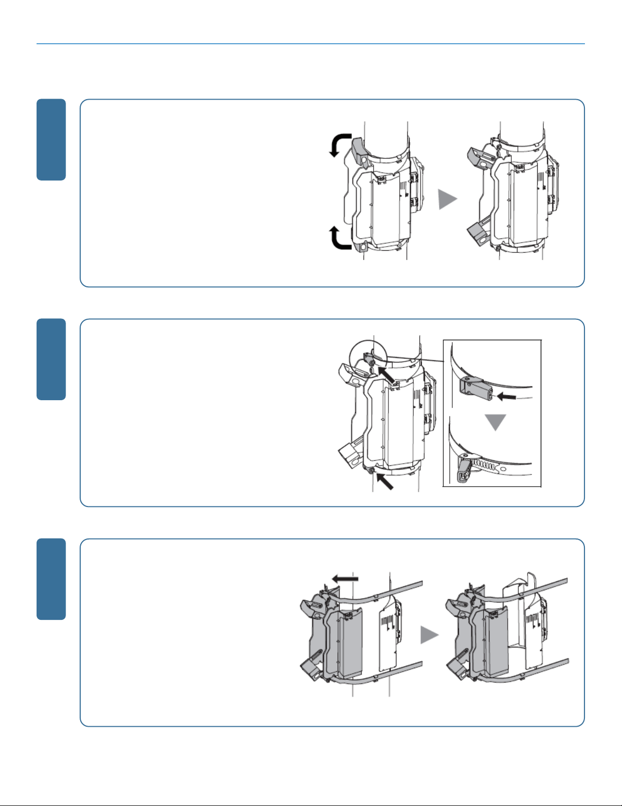
1. Remove the outer door for access to the
interior of the enclosure. Slide it upwards, then
place it in a location to prevent damage.
2. Mark and drill new mounting holes using the
paper template, then drill appropriately sized
holes with a hammer-drill as needed. Use
plastic inserts and mounting screws (taped
to the controller with the enclosure keys) to
secure the controller.
3. Hang the enclosure on these fasteners and
verify the enclosure is mounted level both
vertically and horizontally.
4. Locate the third center mounting hole and
insert the last fastener. Tighten all fasteners to
the enclosure to secure to the vertical surface.
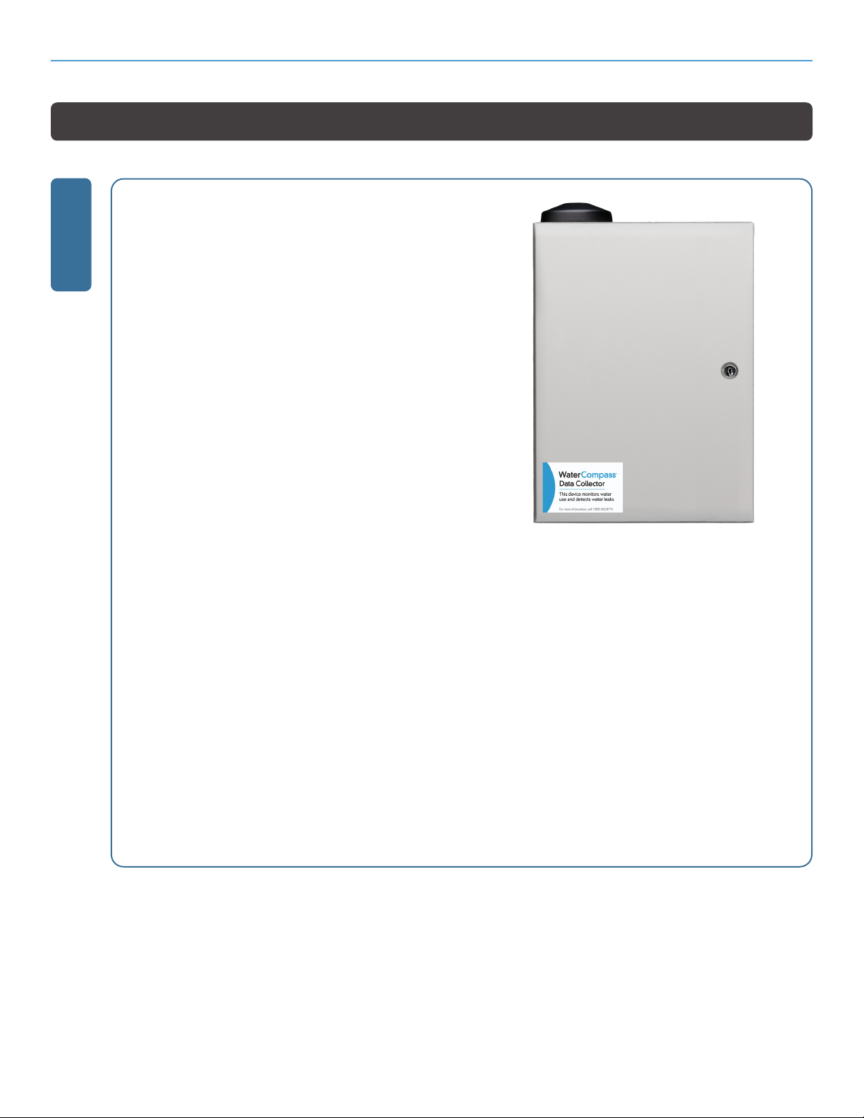
Step 1: Mount the WaterCompass Data Collector Enclosure
1

4800 362 8774 | hydropoint.com | [email protected]
WATERCOMPASS FM300-US-OD FLOW MONITOR: INSTALLATION INSTRUCTIONS 2 ½ - 3”
Step 2: Connect the WaterCompass Data Collector to AC Power
1
The WaterCompass Data Collector incorporates a dual voltage power supply and can be connected
to a single phase 120 V ac or single phase 220 V ac source. Please refer to the 120 V ac or 220 V ac
diagrams on pages 5-6 for proper connections.
The input side of the transformer has 5 color-coded conductors. A label is attached to the
transformer body with identification for each conductor. Two of the conductors (specific to 220 V
ac connections) have been terminated with wire nuts, shortened and tied together with a zip-tie
to avoid confusion for 120 V ac installations.
Do not remove the wire nuts from the 220 V ac connections, as it may cause a short if removed.
1. Confirm that the WaterCompass Data Collector has been securely fastened to a flat, vertical
surface before starting this work.
2. Open the enclosure door and locate the transformer mounted to the chassis. Thread an
approved weatherproof plastic or galvanized metal junction box onto the 1/2” nipple and
secure with a conduit locknut.
3. Connect approved conduit to the underside of the junction box.
4. Pull the required number of conductors and terminate them in the junction box with sufficient
length so that wire nut connections can be made.
5. Remove approximately 1/2” of the wire insulation of the conductor and use an appropriately
sized wire nut based on the number of wire connections being made. Adhere to local and
state electrical codes.

5800 362 8774 | hydropoint.com | [email protected]
WATERCOMPASS FM300-US-OD FLOW MONITOR: INSTALLATION INSTRUCTIONS 2 ½ - 3”
120VAC Applications
For 120VAC wire applications, connect the conductors as illustrated below from the primary side
of the transformer to wiring from an approved electrical source. The unused blue and brown wires
are cut short and terminated with a wire nut.
Step 2: Connect the WaterCompass Data Collector to AC Power, cont.

6800 362 8774 | hydropoint.com | [email protected]
WATERCOMPASS FM300-US-OD FLOW MONITOR: INSTALLATION INSTRUCTIONS 2 ½ - 3”
220VAC Applications
For 220VAC, single-phase applications connect the conductors as illustrated below from the
primary side of the transformer to wiring from an approved electrical source.
Step 2: Connect the WaterCompass Data Collector to AC Power, cont.

7800 362 8774 | hydropoint.com | [email protected]
WATERCOMPASS FM300-US-OD FLOW MONITOR: INSTALLATION INSTRUCTIONS 2 ½ - 3”
Activate the Data Collector by calling
Customer Support at 1-800-362-8774 or by
emailing support@hydropoint.com.
Please be sure to have the following
information when calling to activate the Data
Collector:
• Serial number of the Data Collector
• SIM of the Data Collector
• Location of the installation
Both numbers can be found on the outside of
the shipping box and the help menu on the
display of the data collector.
Note: since the Data Collector/OXR is being
used for WaterCompass, it does not need to
have an Optiflow subscription activated.
Step 3: Activate the WaterCompass Data Collector
Step 4: Choose a Location to Install the Flow Monitor
Choose a proper location for installing the
flow monitor. Information about choosing
the proper location can be found in
Appendix A of this document.
Note that the flow direction is configured
to flow from left to right. If the flow
direction needs to be changed, refer to the
instructions in Appendix C.
1
1

8800 362 8774 | hydropoint.com | [email protected]
WATERCOMPASS FM300-US-OD FLOW MONITOR: INSTALLATION INSTRUCTIONS 2 ½ - 3”
Step 5: Attach the Flow Monitor to the Pipe
1
Before beginning, take some time to familiarize yourself with the part names and functions of the
flow monitor.
Caution:
During the installation process, it is very important to not slide the bracket with the rubber backing
against the pipe. Doing so may damage the backing and impede the installation process. If you do need
to reposition the bracket, completely loosen the connections and carefully lift off.

9800 362 8774 | hydropoint.com | [email protected]
WATERCOMPASS FM300-US-OD FLOW MONITOR: INSTALLATION INSTRUCTIONS 2 ½ - 3”
Open the worm screw covers.
Loosen the worm screws.
Raise the clamp to detatch the belt
from the upper bracket.
2
3
4
Step 5: Attach the Flow Monitor to the Pipe, cont.

10 800 362 8774 | hydropoint.com | [email protected]
WATERCOMPASS FM300-US-OD FLOW MONITOR: INSTALLATION INSTRUCTIONS 2 ½ - 3”
Determine the installation location of the
lower bracket. The orientation of the main
unit’s display is determined by the installation
orientation of the lower bracket.
Caution: Damage to the rubber backing can
occur if the lower bracket is moved after it
has been attached to the pipe. Do not slide
the bracket on the pipe when tightened.
If the bracket position needs to be adjusted,
completely loosen the connections and lift
carefully from the pipe.
Determine the installation orientation of
the upper bracket. Make sure the metal
belts and cable holders are on the same
side of the pipe.
Raise the clamp to detatch the belt
from the upper bracket.
5
6
7
Step 5: Attach the Flow Monitor to the Pipe, cont.

11 800 362 8774 | hydropoint.com | [email protected]
WATERCOMPASS FM300-US-OD FLOW MONITOR: INSTALLATION INSTRUCTIONS 2 ½ - 3”
Adjust the position of the upper
bracket to align the alignment
guide with the lower bracket.
Ensure that the red arrow sticker on
the upper bracket aligns with the red
arrow sticker on the lower bracket.
Do not move the lower bracket while
it is in contact with the pipe. Doing so
may damage the rubber backing.
To detect the flow rate stability,
adjust the unit position in the
longitudinal direction of the pipe.
Adjust the position of the upper
bracket so that the scale position is
the same on the left and right.
Press the side of the upper bracket
to insert the upper bracket
into the alignment guide.
To detect the flow rate stability, adjust the
unit position according to the pipe angle.
Hand tighten the hose clamps.
Close the screw covers.
Firmly tighten the metal belt screws.
8
9
10
11
Step 5: Attach the Flow Monitor to the Pipe, cont.

12 800 362 8774 | hydropoint.com | [email protected]
WATERCOMPASS FM300-US-OD FLOW MONITOR: INSTALLATION INSTRUCTIONS 2 ½ - 3”
Fix the main unit in place on the
upper bracket.
Tighten the left and right screws
evenly, a little bit at a time.
Connect the unit connection cable to
the main unit and sub unit.
Pay attention to the orientation of the
connector when connecting it. Failure
to do so may result in damage to the
connecting pins.
Fix the unit connection cable to the
cable holders.
Freely install the cable in the cable holders.
12
13
14
15
Step 5: Attach the Flow Monitor to the Pipe, cont.

13 800 362 8774 | hydropoint.com | [email protected]
WATERCOMPASS FM300-US-OD FLOW MONITOR: INSTALLATION INSTRUCTIONS 2 ½ - 3”
Note: The Flow Monitor being installed may
look different than what is pictured. The wiring
connections and process remain the same.
1. Power-off the two-wire during the
installation of any two-wire device.
2. Unwrap the wire bundle that is attached
to the WT-H20 Decoder.
3. Connect the red and black wires from the
WT-H20 Decoder to the red and black
wires from the two-wire path. Be sure to
maintain polarity by connecting red to red
and black to black. Use wire nuts on all
connections.
Step 6: Connecting the Flow Monitor to the 2-Wire Path
Step 7: Connecting the Flow Monitor Power Supply
Note: The Flow Monitor being installed may look different than what is pictured. The wiring
connections and process remain the same.
1. Find the brown and green wires in the wire bundle that is attached to the WT-H20 Decoder.
2. Find the corresponding brown and green wires exposed at the end of the power supply cord.
3. Be sure to maintain polarity by connecting green to green and brown to brown. Attach the plug
in end of the power cord to the power supply.
4. Plug the power cord into a 110V electrical outlet.
1
1

14 800 362 8774 | hydropoint.com | [email protected]
WATERCOMPASS FM300-US-OD FLOW MONITOR: INSTALLATION INSTRUCTIONS 2 ½ - 3”
1. Turn on the power to the Flow
Monitor. The Stability indicator lights
up on the lower left of the display
after the initial installation.
2. The stability indicator shows the
rough stability of detection. In case
of unstable detection or no detection,
see “Points to be Checked” in the
appendix of this document.
3. There should be 3 or 4 bars bars
visible. If anything less, re-install
the flow monitor. If that does not
improve stability, call support.
Step 8: Validate Proper Flow Stability
1

15 800 362 8774 | hydropoint.com | [email protected]
WATERCOMPASS FM300-US-OD FLOW MONITOR: INSTALLATION INSTRUCTIONS 2 ½ - 3”
1. From the Data Collector control panel,
Press SETUP.
2. Press --> until CONFIGURE H2O
2-WIRE displays (setup 15).
3. Press + or – until Program Decoders
displays.
4. Press SELECT.
5. Press *. The controller reads the decoder
and assigns it as a flow sensor. If you
need to change FS number, press + or –.
6. Press *.
7. Press + or – to set the power level.
Power levels for each station can be
adjusted independently. The power
defaults to low. for most stations, low
power is sufficient. However, some
stations may require more power due
to a longer 2-wire path or a higher
electrical requirement for a specific
valve type.
8. Press * two times to assign the decoder.
The following screen displays, confirming
a successful assignment:
In order for the decoder to communicate with
the WaterCompass Data Collector, you will
need to program it using the the Station
Program ports located on the mini chassis
board
1. Plug the decoder into the Station Decoder
Program Terminal block as illustrated.
1
2
Step 9: Program the WT2W-H20 Decoder that is connected to the Flow Monitor

16 800 362 8774 | hydropoint.com | [email protected]
WATERCOMPASS FM300-US-OD FLOW MONITOR: INSTALLATION INSTRUCTIONS 2 ½ - 3”
1. Disconnect the decoder 2-wire from the station decoder programming terminal block.
2. Matching red to red and black to black, plug the 2-wire into the 2-wire connection terminals on
the system board
Note: All terminals are the same, so the 2 wire cable can be added to the top or bottom of the
terminal block.
Install the power supply for the WT-H20 decoder inside the cabinet of the WaterCompass Data
Collector. You can extend the distance between the power supply and the WT-H20 decoder up to
2500 feet with additional two-wire.
3
4
Step 9: Program the WT2W-H20 Decoder that is connected to the Flow Monitor
Step 9: Program the WT2W-H20 Decoder that is connected to the Flow Monitor, cont.

17 800 362 8774 | hydropoint.com | [email protected]
WATERCOMPASS FM300-US-OD FLOW MONITOR: INSTALLATION INSTRUCTIONS 2 ½ - 3”
1. Press SETUP.
2. Press --> until the Configure H20 2-Wire
screen displays (SETUP screen 15)
3. Press SELECT to edit.
4. Press + until the Flow Sensors displays.
5. Press SELECT to edit..
6. Configure for 2-Wire using the + and -
buttons.
1. Press FLOW.
2. Press --> until the SELECT FLOW SENSOR
screen displays (screen 02-07-02).
3. Press + or - to select Custom.
1. Press* to configure.
2. Press --> to Edit.
3. Press + or - to select the pipe size.
4. Press --> to select the K value.
5. Press Select to edit. You will need to enter in
the value of 60.1.
6. Press + or - to change the value of the digit.
7. Press --> to move to the next digit until the
value is complete.
Step 10: Enter the K Value into the WaterCompass Data Collector
Step 11: Configure Flow Sensor
1
1

18 800 362 8774 | hydropoint.com | [email protected]
WATERCOMPASS FM300-US-OD FLOW MONITOR: INSTALLATION INSTRUCTIONS 2 ½ - 3”
1. Press FLOW.
2. The Flow Sensor will display. If flow is
being red, you should see the flow sensor
listed followed by the number in GPM’s.
1. Remove front panel so you can
access the back side of the panel.
2. Disconnect 24 V ac power by unplugging
the 24 V ac cable from the mini chassis
3. Insert the OptiFlow key into the
USB port. located on the back
side of the front panel.
4. Reconnect 24 V AC power supply.
1. On the controller front panel, press HELP.
2. Press --> until the Firmware Version screen
displays (Help 03). displays.
3. Press -->.
4. Press * to upgrade, and follow the prompts to
complete the process.
5. After the upgrade, check the firmware version.
Make sure that the firmware version is 8.6.4 or
higher. If it is not, contact Customer Support
and have them push the latest firmware version
to the WaterCompass Data Collector.
Step 12: Verify the Flow in GPM on the WaterCompass Data Collector
Step 13: Update Controller Firmware
1
1
2
STOP!
Before leaving the site, you must upgrade the firmware to OptiFlow on the WaterCompass Data
Collector. This must be done so flow can be accurately read. Please follow the instructions below.

19 800 362 8774 | hydropoint.com | [email protected]
WATERCOMPASS FM300-US-OD FLOW MONITOR: APPENDIX A
Appendix A: Selecting an Installation Location
How to Select an Installation Location
Some important factors must be considered BEFORE installing the FM300-US Flow Monitor. Read and follow the
guidelines below to ensure that the flow monitor is installed in just the right location to deliver the results you need.
• Choose a location indoors
• Choose a location that captures all the flow being monitored
• Install on a pipe that is always full of water
• Ensure that the monitor has direct contact with the pipe
• Install in a location that is free of turbulence
• Install in a room where there is 120V power
Choose a location that captures all the flow being monitored
Whether you want to monitor an entire building or just a floor of a building, you will need to install the device in a place
indoors that captures all of the flow entering the section of building that you want to monitor.
For example, if the objective is to monitor the flow for an entire building, the device should be located on the pipe
entering the building from the water source. If the objective is to monitor a specific floor of a building, the device needs
to be installed on the pipe supplying all the water for that floor.
Install on a pipe that is always full of water
The device needs to installed in a location where the pipe is always filled with water. Be aware of situations where low
flow may allow the pipe to be only partially full:
Ensure that the monitor has direct contact with the pipe
The flow monitor needs to be installed directly on the pipe. Do not install the device on top of insulation or in areas that
contain rust or seams.
Install in a location that is free of turbulence
Changes in pipe size and direction can create turbulence in the water and stop the monitor from accurately reading
flow. Select an installation location that will ensure adequate distance upstream and downstream of the monitor to
allow any turbulence to settle before passing the flow monitor.
Be sure to select a location that is:
• Far enough downstream to allow turbulence to settle
• UPSTREAM of pressure regulating devices
• Far enough away from sources of large pulsation (like from a pump)

20 800 362 8774 | hydropoint.com | [email protected]
WATERCOMPASS FM300-US-OD FLOW MONITOR: APPENDIX A
You can use the chart below to help ensure that you are leaving enough space upstream for proper flow.
You will need a caliper and a tape measure to determine the diameter and length of existing pipe.
The Length (L) should be greater than X times the diameter of the pipe
based on the specific pipe change described in the chart.
For example, on a 2” pipe the monitor’s best section of pipe is directly downstream of a 90°
elbow. We’d look for at least 10x2” or 20” of pipe between the end of the bend and the
beginning of the monitor to allow for the turbulence caused by the elbow to settle.
Install in a room where there is 120V power
The WaterCompass FM300-US Flow Monitor runs on DC power. It is best to install the device in
a room where there is a power outlet or where power conduit can be tapped into for use.
The DC supply wire and the two-wire can run in parallel and inside the same outer jacket.
The DC supply wire cannot have more than 25ohms* of resistance: 12.5 out, 12.5 back.
Wire lengths for power can be extended according to the gauge of the two wire that connects
the flow decoder to the flow meter. Below is a chart listing wire gauges and length limits.
Wire Gauge #18 #16 #14 #12
Wire Length 1,900 3,100 5,000 8,000
Appendix A: Selecting an Installation Location, cont.
Other manuals for WaterCompass FM300
1
This manual suits for next models
2
Table of contents
Other HydroPoint Measuring Instrument manuals
Popular Measuring Instrument manuals by other brands

Endress+Hauser
Endress+Hauser Liquiline System CA80AM Brief operating instructions

Extech Instruments
Extech Instruments 475040 user guide

Sensus
Sensus PulseRF-Mei MS 2820 installation manual

Mitutoyo
Mitutoyo LGF-110ZL-B quick start guide

National Instruments
National Instruments VirtualBench VB-8034 quick start

Kromek
Kromek D3S Static Node user manual