HydroQuip U Series User manual

U-SERIES LOW LEVEL PROGRAMMING
LINE 2
NEUTRAL
LINE 1
GROUND
WARNING - Secure wires as defined by the NEC and in compliance with any local codes in effect
at the time of installation. The system data label contains specific electrical information required for
installation. A wiring diagram is provide with every system and is located inside the control systems
hinged cover. The wiring diagram may contain “manufacturers notes” vital to your particular
installation. Typical 120-Volt and 240-Volt installations are depicted below.
Use the illustrations and instruction below to connect your input power wiring. Always refer to the
wiring diagram provided with your control (located inside the hinged cover) prior to connecting any
wires.
U-SERIES VOLTAGE CONNECTION
120-Volt
NEUTRAL
LINE 1
GROUND
Blue & White Neutral Wires Crimped Together
GROUND LUG PROVIDED
!Connect input Neutral to White Wire (crimped together with Blue wire).
!Connect Line 1 to Black Wire.
!Connect Line 2 to Blue Wire.
!Connect input Neutral to White Wire (crimped together with Blue wire).
!Connect Line 1 to Black Wire.
240-Volt
BLUE
WHITE
BLACK
GROUND LUG PROVIDED
BLUE
WHITE
BLACK
The Low Level settings such as Current Settings (limiting heater activation for low amperage
systems), Single or Dual Speed Pump, Accessory (pump or blower) Configuration, Circulation
Pump, Temperature Display (Fahrenheit or Celsius) and Light Configuration may be accessed
directly from the spaside control.
Press and hold the Light Key for approximately 20 seconds, the first
parameter will appear. Use the Up/Down Arrow Key to adjust the setting.
Press the Light Key to change to the next parameter .
4
LIGHT KEY
Current Limiting:
HC = High Current (No Current Limiting) *
LC = Low Current (heater will turn off with high speed pump or accessory
operation)
Pump 1 Configuration:
SP 1 = Single Speed
SP 2 = Dual Speed *
Accessory Configuration:
BL 0 = Not Installed
BL 1 = Single Speed Pump 2 or Blower Installed *
Circulation Pump:
CP 0 = No Circulation Pump*
CP 1 = Circulation Pump
Temperature Display:
Tu F = Fahrenheit *
Tu C = Celsius
Light Configuration:
LI 1 = Single Intensity (On/Off)*
LI 2 = Two Intensities
* notes default setting
Note: If the error code “FLC” appears after programming simply cycle the power to
the control unit and the error should clear.

U-SERIES - BASIC OPERATION U-SERIES - ERROR MESSAGES
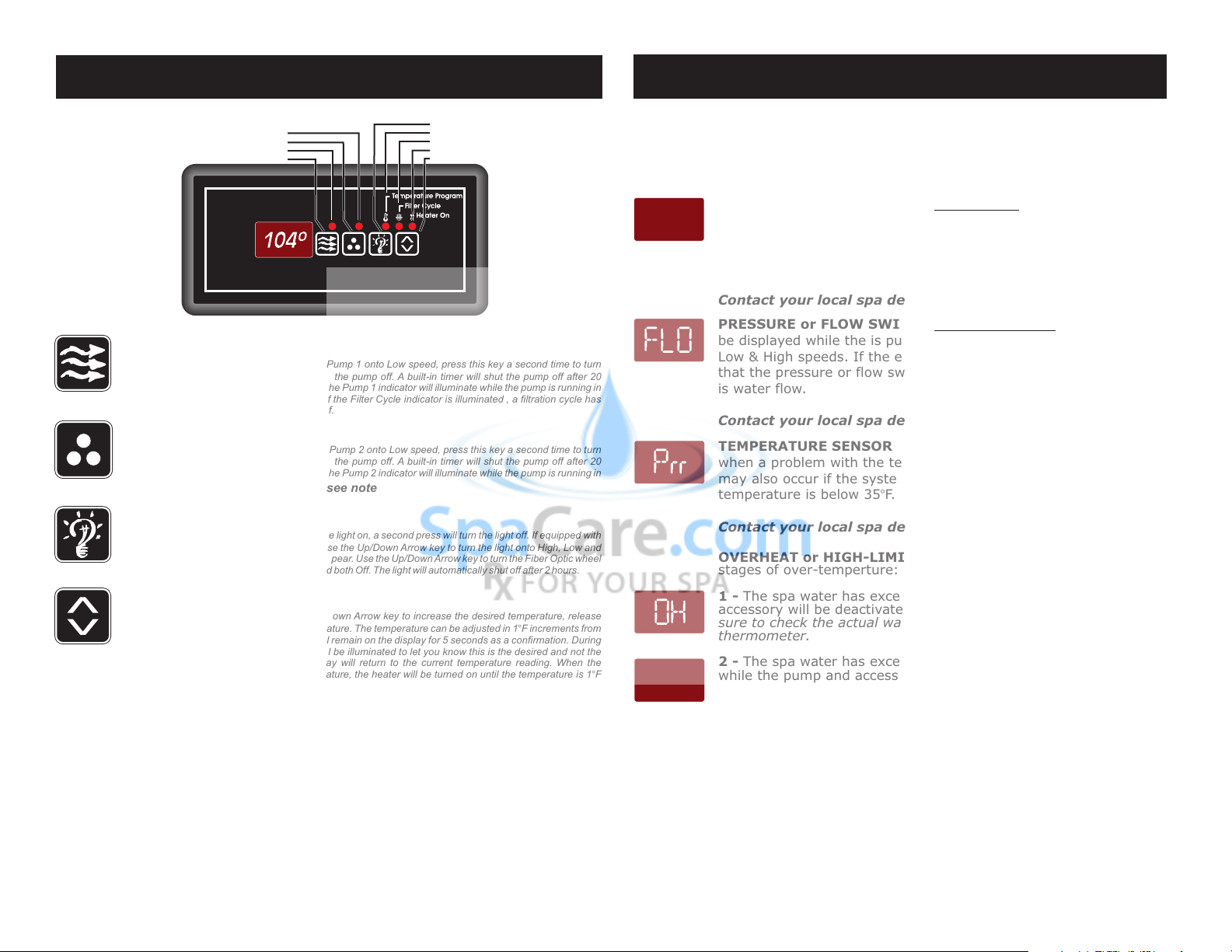
Pump 1 Key: Press this key once to turn Pump 1 onto Low speed, press this key a second time to turn
Pump 1 onto High speed, a third press will turn the pump off. A built-in timer will shut the pump off after 20
minutes of operation unless done so manually. The Pump 1 indicator will illuminate while the pump is running in
High speed and flash while it is in Low speed. If the Filter Cycle indicator is illuminated , a filtration cycle has
begun and you will not be able to turn the pump off.
Pump 2 Key: Press this key once to turn Pump 2 onto Low speed, press this key a second time to turn
Pump 2 onto High speed, a third press will turn the pump off. A built-in timer will shut the pump off after 20
minutes of operation unless done so manually. The Pump 2 indicator will illuminate while the pump is running in
High speed and flash while it is in Low speed.
Light/Enter Key: Press this key to turn the light on, a second press will turn the light off. If equipped with
Fiber Optic: Press this key once to show “L1”. Use the Up/Down Arrow key to turn the light onto High, Low and
Off. Press the light key a second time, “F1” will appear. Use the Up/Down Arrow key to turn the Fiber Optic wheel
and light on, Fiber Optic wheel off with light on and both Off. The light will automatically shut off after 2 hours.
Temperature Set Key: Press the Up/Down Arrow key to increase the desired temperature, release
and press again to decrease the desired temperature. The temperature can be adjusted in 1BF increments from
59BF to 104BF (5BC to 40BC). The new setting will remain on the display for 5 seconds as a confirmation. During
this time the Temperature Program indicator will be illuminated to let you know this is the desired and not the
actual temperature. After 5 seconds the display will return to the current temperature reading. When the
temperature drops to 1BF below the set temperature, the heater will be turned on until the temperature is 1BF
above the set temperature. The Heater “On” indicator will illuminate while the heater is on and flash when there is
a call for heat and the heater has not yet been activated.
AUXILIARY INDICATOR
AUXILIARY KEY
PUMP INDICATOR
PUMP KEY
LIGHT KEY
TEMP. PROGRAM INDICATOR
FILTER CYCLE INDICATOR
HEATER “ON” INDICATOR
TEMP. SET KEY
85-0150-B1 REV.1 12/07
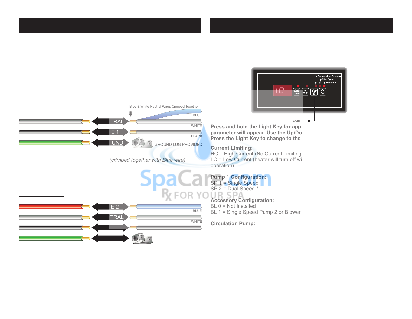
Note: This system may be configured to operate an accessory circuit as noted
above. If your system has been configured to operate one pump only the spaside
label will be configured as such: It will include a “Pump”, “Light”, “Up Arrow” &
“Down Arrow”. Those keys operate as noted above with the exception of the
temperature settings, it is now handled by separate keys.
* see note
ERROR INDICATION
fLC
To assist the user in identifying problems with the spa, the system will display an
error message. These messages will be helpful when communicating with your local
dealer or qualified technician if a problem should arise.
PRESSURE or FLOW SWITCH ACTIVATED - This error will be
displayed only when the pump is not activated. Cycle the pump
through Low & High speeds then off. If the error does not clear
this is an indication that the pressure or flow switch is activated
with no water flow.
Contact your local spa dealer
fLo PRESSURE or FLOW SWITCH NOT ACTIVATED - This error will
be displayed while the is pump running. Cycle the pump through
Low & High speeds. If the error does not clear this is an indication
that the pressure or flow switch has not activated although there
is water flow.
Contact your local spa dealer
PTEMPERATURE SENSOR MALFUNCTION - This error will occur
when a problem with the temperature sensor exists. This error
may also occur if the system is activated while the water
temperature is below 35BF.
Contact your local spa dealer
OH
OVERHEAT or HIGH-LIMIT PROTECTION - There are three(3)
stages of over-temperture:
1 - The spa water has exceeded 112BF. The heater, pump and
accessory will be deactivated until the water cools to 109BF. Be
sure to check the actual water temperature with an accurate
thermometer.
2 - The spa water has exceeded 119BF. The heater will deactivate
while the pump and accessory will still operate. The blower (if
equipped) can be activated to help cool the water. WATER MUST
BE BELOW 119BF AND POWER MUST BE RESET TO CLEAR
THE “HL” ERROR
A dirty spa filter can also cause a restricted flow of water, be sure
the filter is cleaned regularly and ensure all water shutoff valves
are open.
If the system has been operating normally until now, the pump
may be overheating the spa. Refer to “Programing Filtration” on
page X and reduce the duration and/or number of cycles per day.
3 - If you’ve eliminated items 1 & 2 as problems, the high-limit
sensor may have malfunctioned.
Contact your local spa dealer
Hl

Programming Filter Cycles: You may choose to filter the spa 1, 2 or 3 times per day
as required to keep the water clean and sanitary. Press and hold the Pump key for 5
seconds. The current setting will be displayed. Use the Up & Down Arrow keys to
increase or decrease the frequency of the filtration cycles per day. The filter cycle is now
set. To start a filter cycle immediately, press the Pump key while the value is displayed.
The cycles will repeat every 8, 12 or 24 hours within a 24-hour period starting from
the time programmed. It is recommended to schedule the filtration cycles so they do
not interfere with sleeping hours.
Programming Filter Cycle Duration: You may choose to filter your spa 60, 120 or
180 minutes per cycle as required to keep the water clean and sanitary. Press and
hold the Light key for 5 seconds. The current duration of the filter cycle will be
displayed. Use the Up & Down Arrow keys to increase or decrease the duration of
the filter cycle. The duration is now set. To start a filter cycle immediately, press
both the Light key while the value is displayed.
Setting Fahrenheit and Celsius Degrees: Is set by a physical jumper located on
the PCB.
* If the spa is being used during the filter cycle, the cycle will be suspended
for a period of 40-minutes or until the spa is no longer in use.
PROGRAMMING FILTRATION
ERROR INDICATION
fLC
To assist the user in identifying problems with the spa, the system will display an
error message. These messages will be helpful when communicating with your local
dealer or qualified technician if a problem should arise.
PRESSURE or FLOW SWITCH ACTIVATED - This error will be
displayed only when the pump is not activated. Cycle the pump
through Low & High speeds then off. If the error does not clear
this is an indication that the pressure or flow switch is activated
with no water flow.
Contact your local spa dealer
fLo PRESSURE or FLOW SWITCH NOT ACTIVATED - This error will
be displayed while the is pump running. Cycle the pump through
Low & High speeds. If the error does not clear this is an indication
that the pressure or flow switch has not activated although there
is water flow.
Contact your local spa dealer
CHEMICAL WATER TREATMENT
Your dealer is familiar with local water conditions and which chemicals
are compatible with the water and are designed specifically for your spa. This is
the best person to advise you on proper water quality management.
The one thing you can do to insure years of trouble free equipment
operation is to maintain proper water chemistry.
Two basic goals of the chemical water treatment are sanitizing and
balancing the water.
Sanitizing simply means keeping the water free from living
microorganisms including algae, bacteria and viruses. The current most popular
chemicals for sanitizing include chlorine, bromine and ozone.
Balancing water means establishing a balance among pH, total
alkalinity and total hardness. Water that is unbalanced can corrode the spa and
it's support equipment or leave deposits of minerals. Properly balanced water is
essential to allow the sanitizing chemical to work effectively. There are
numerous chemical additives to help you in controlling pH, total hardness and
total alkalinity. NEVER use softened water when filling your spa. Softened
water is extremely corrosive to the metal parts of the spa equipment and may
lead to an unforeseen failure.
Sometimes, despite your most diligent efforts, your water may become
too far out of balance to be managed chemically. At this point it is probably
better to drain and clean the spa and start over with fresh water.
Equipment failure caused by improper water chemistry will not be
covered under warranty.
FILTRATION SYSTEM
Please refer to your Spa Manufacturer's owner's manual regarding the
operation, maintenance and cleaning of your filtration system.
Dirty or clogged filters can cause flow restrictions and you may experience
difficulty in reaching and/or maintaining desired heat levels.
WINTERIZING
When freezing weather and/or power losses are expected, contact your local
spa dealer for freeze protection or winterizing recommendations for both the
spa and the equipment system. Freeze related damage is not covered by the
warranty.
11 8
This manual suits for next models
1
Popular Hot Tub manuals by other brands

Penner Manufacturing
Penner Manufacturing CASCADE ALCOVE Safe Operation & Daily Maintenance Instructions

Aqua Pulse Spas
Aqua Pulse Spas Lorne Luxury user manual

infinite spa
infinite spa CHAMPION 6 places manual

Dynasty Spas
Dynasty Spas SC-MP-DY4 Quick reference card

CalderaSpas
CalderaSpas CalderaSpas Utopia Series owner's manual

Aquatic
Aquatic HOTSOAK 79 AI6036SVHS Specification sheet