manuals.online logo
Brands
  1. Home
  2. •
  3. Brands
  4. •
  5. HydroTherm
  6. •
  7. Boiler
  8. •
  9. HydroTherm HW Series Manual

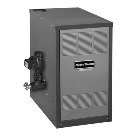
HydroTherm HW Series Manual

HW2-805
ATU
IAL
STALLATI
INST
GAS
& E
CTION
LE
G
DESIGNED AND TESTED ACCORDING TO A.S.M.E. BOILER AND PRESSURE
VESSEL CODE, SECTION IV FOR MAXIMUM ALLOWABLE WORKING PRESSURE OF
50 PSI, 345 kPa WATER
NOTE TO INSTALLING CONTRACTOR: READ THESE INSTRUCTIONS CAREFULLY.
THEY WILL SAVE YOU TIME IN ASSEMBLING BOILER PROPERLY.
Do not store or use gasoline or other flammable vapors and liquids
in the vicinity of this or any other appliance.
What to do if you smell gas:
,Do not try to light any appliance.
,Do not touch any electrical switch. Do not use any phone in your
building.
, immediately call your gas supplier from a neighbor's phone. Follow
the gas supplier's instructions.
, If you cannot reach your gas supplier, call the fire department.
installation and service must be performed by a qualified installer,
service agency or the gas supplier.
INSTALLER, THESE INSTRUCTIONS TO BE AFFIXED ADJACENT TO THE BOILER.
CONSUMER, RETAIN THESE INSTRUCTIONS FOR FUTURE REFERENCE PURPOSES.
TEL. (413) 564=5515 FAX (413) 568-9613
In Canada: 5211 Creekbank Road, Mississauga, Ont. L4W 1R3 (905) 625=2991 Fax (905) 625-6610
Page2 HWNATURALORPROPANEBOILER
iNSTALLATiONANDOPERATINGiNSTRUCTiONS
Ne pas entreposer ni utiliser d'essence ou ni d'autres vapeurs ou liquides inflammables
proximite de cet appareil ou de tout autre appareil.
QUE FAIRE Sl VOUS SENTEZ UNE ODEUR DE GAZ:
•Ne pas tenter d'allumer d'appareil.
•Ne touchez a aucun interrupteur; ne pas vous servir des telephones se trouvant darts
le b_timent.
•Appelez immediatement votre foumisseur de gas depuis un voisin. Suivez les
intructions du foumisseur.
•Si vous ne purvez rejoindre le foumisseur, appelez le service des incendies.
L'installation et I'entretien doivent _tre assures par un installateur ou un service
d'entretien qualifie ou par le foumisseur de gaz.
CONTENTS
Getting Started
Boiler Ratings & Capacities
Locating the Boiler
Combustible Floor Option
Air for Combustion
Chimney & Vent Pipe Connections
Heating System Piping
Gas Supply Piping
Electrical Wiring
Starting the Boiler
Operating the Boiler
Checking & Adjusting
Boiler Maintenance
Instructions to the Owner
Replacement Parts
Canadian Supplement
Health Warnings
page 2
page 3
page 3
page 5
page 5
page 6
page 8
page 11
page 12
page 18
page 20
page 23
page 24
page 25
page 26
page 28
page 30
BEFORE YOU START
These instructionscover the HW gas fired, low pressure,
sectional, cast iron hot water boiler. HW boilers have
been design certified by CSA under the latest revision of
ANSI-Z21.13 for gas fired low pressure steam and hot
water boilers, for use with natural and propane gas.
Each unit has been constructed and hydrostatically
tested for a maximum working pressure of 50 psi, 345
kPa in accordance with the A.S.M.E. Boiler and
Pressure Vessel Code, Section IV for cast iron boilers.
Each boiler has been equipped with a 30 psi pressure
relief valve.
This manual covers the application, installation,
operation and maintenance of a HW low pressure hot
water boiler,
To obtain the safe, dependable, efficient operation and
long life for which this boiler was designed, these
instructions must be read, understood and followed,
HWNATURALORPROPANEBOILER
iNSTALLATiONANDOPERATINGiNSTRUCTiONS Page3
Directall questionsto yourHydrothermdistributoror
writetotheCustomerServiceDepartment,260North
ElmStreet,Westfield,MA01085.Alwaysincludethe
modelandserialnumbersfromtheratingplateofthe
boilerinquestion.
Theownershouldmaintainarecordofallservicework
performedwiththedateandadescriptionofthework
done.Includethenameoftheserviceorganizationfor
futurereference.
Whererequiredbytheauthorityhavingjurisdiction,the
installationmustconformtotheStandardforControls
andSafetyDevicesfor AutomaticallyFiredBoilers,
ANSI/ASMECSD-1.
Theinstallationmustconformto therequirementsof
theauthorityhavingjurisdictionor,in theabsenceof
suchrequirements,to the NationalFuelGasCode,
ANSIZ223.1/NFPA54-latestrevision.In Canada,
installationmustbeinaccordancewiththerequirements
of CAN/CGAB149.1or 2 InstallationCodefor Gas
BurningAppliancesandEquipment.
BOILER RATINGS AND CAPACITIES
Before undertaking the installation of the HW check
the boiler rating plate to ensure that the boiler is the
proper size for the job. The "Net I=B=R Ratings" specify
the equivalent amount of direct cast iron radiation that
the boiler can handle under normal conditions. Also
ensure that the boiler has been set up for the type of
gas available at the installation site. Other important
considerations are the availability of an adequate
electrical supply, fresh air for combustion and a suitable
chimney or vent system.
NOTES:
1. For altitudes above 2000 ft, 610 m, ratings should
be reduced at the rate of 4% for each 1000 ft, 305
mabove sea level, 10% in Canada.
2. If ordering a boiler for use with LP gas add a P to
the model number, ie PHW.
BOILER LOCATION
.Locate the boiler in an area that provides good
access to the unit. Keep in mind that servicing may
require the removal of jacket panels. Accessibility
clearances must take precedence over fire
protection clearances.
2. An optimum site will be level, central to the piping
system, close to a chimney and have adequate
fresh air for combustion.
.Ensure that the floor is structurally sound and will
support the weight of the boiler. This boiler is
designed for non combustible floors only! A special
base supplied by Hydrotherm must be used if the
boiler is to be installed on a combustible floor.
NEVER USE A SUBSTITUTE BASE ON A
COMBUSTIBLE FLOOR! Never install this boiler on
carpeting!
.DO NOT install this boiler in a location that would
subject any of the gas ignition components to direct
contact with water or excessive moisture during
operation or servicing.
5. DO NOT place this boiler in a location that would
restrict the introduction of combustion air into the
boiler. NEVER store objects on or around the boiler.
Page4 HWNATURALORPROPANEBOILER
INSTALLATIONANDOPERATINGINSTRUCTIONS
,If the boiler is to be located in an alcove, closet or
other confined space the distances from the boiler
and it's vent system to all combustible construction
must be equal to or greater than the minimum
clearances in Figure 1. When installed in a closet or
confined space two permanent openings of equal
area adjoining another room or rooms having
sufficient volume to meet the requirements of an
unconfined space must be provided. Each opening
must have a minimum free area of one square inch
per 1000 Btu/hr, 2200 mm2/kWbased on the total
input rating of all gas utilization equipment in the
confined area. Each opening must be no less than
100 in 2, 64516 mm 2, in size. The upper opening
must be within 12 in, 305mm, of, but not less than
3 in, 76 mm, from the top of the enclosure. The
bottom opening must be within 12 in, 305 mm, of,
but not less than 3 in, 76 ram, from the bottom of the
enclosure.
Figure 1:Clearances to Combustible Construction
FRONT
A
B
C
D
E 7
F 4
AL = Alcove
CL = Closet
in
24
6
4
AL
mm
610
152
102
178
102
in
51
2
6
4
7
4
mm
1295
51
152
102
178
102
For
Servicing
in mm
N/A N/A
N/A N/A
6152
4 102
10 254
10 254
CL
*No Front Wall in Alcove
HW NATURAL OR PROPANE BOILER
INSTALLATION AND OPERATING INSTRUCTIONS
COMBUSTIBLE FLOOR OPTION
The HW boiler has been designed for use on
noncombustible floors only. If a HW boiler is to be
installed on combustible flooring of any type, it MUST
be installed using the Special Base designed by
Hydrotherm. Do NOT use any base other than the one
specifically designed for it if installing a HW boiler on
combustible flooring.
To order the Special Base contact the nearest
Hydrotherm distributor and ask for the "Noncombustible
Floor Pan" part number referenced in the Replacement
Parts List in back of the IOM.
Determine where the boiler will be located by following
the instructions in the Boiler Location section of this
manual. Place the Special Base in this location and
fasten it in place to prevent it from moving while the
boiler is being placed on it.
If the HW is being installed inan alcove or closet ensure
that the minimum distance to combustible construction
requirements, listed in Figure 1, are met.
Figure 2: Special Base installation on
Combustible Flooring
FRONT SUPPORT
GRILL CHANNEL
Remove the sheet metal base pan attached to the
boiler. Position the boiler in front of the Special Base. It's
suggested that two lengths of 3" pipe the width of the
boiler, or longer, be placed under the boiler base side
panels.
COMBUSTION AiR
CAUTION: Be careful not to damage the burners,
pilot assembly or any other gas train components
during this procedure, if a component is damaged,
replace it!
Carefully roll the boiler up to the front of the Special
Base. Align the boiler base side panels with the Special
Base support channels. Using great care, slide the boiler
onto the Special Base.
CAUTION: Never lift the boiler by the jacket panels
or flue collector/draft diverter or severe damage to
the boiler may result!
Center the boiler from side to side on the Special Base.
Ensure that the back of the burner base side panels
are flush with the back of the Special Base support
channels. Install the front grill supplied with the Special
Base. Complete the installation in accordance with the
instructions set forth in this manual.
Table 1: Vent and Chimney Dimensions
HW HW HW HW HW HW HW
Boiler Size 50 75 1O0 125 150 175 200
Vent Pipe 5566778
Dia. (In.)
Chimney 8x8 8x12
Flue Size
Chimney 18 18 18 17 17 17 16
Height (Ft.)
Page 5
Page 6 HW NATURAL OR PROPANE BOILER
iNSTALLATiON AND OPERATING iNSTRUCTiONS
To operate properly and safely this boiler requires a
continuous supply of air for combustion. Oxygen is used
by the burners in the boiler to burn the gas. In addition,
air is also used to assist in the safe disposal of the
products of combustion. This air is known as dilution
air and mixes with the products of combustion to assist
in it's exit through the flue pipe and chimney. An
adequate supply of outside air must be available to
replace that used by these processes.
Older houses often have enough "leakage" to provide
an adequate amount of combustion air provided that
the demand for combustion air is not too great. Homes
that are relatively new or "tight" will most likely require
the installation of a fresh air duct or other means of
providing air for combustion. Any home utilizing other
gas burning appliances, a fireplace, wood stove or any
type of exhaust fan must be checked for adequate
combustion air when all of these devices are in operation
at one time. Sizing of an outside air duct must be done
to meet the requirements of all such devices.
Table 2: Combustion Air Duct Sizing
Input Btuh Input Btuh Input Btuh
Fresh Air 1/4" Wire Metal Wooden
Duct Size Mesh Screen Louvers Louvers
3" x 12" 144,000 108,000 36,000
8"x 8" 256,000 192,000 64,000
8"x 12" 384,000 288,000 96,000
8-1/2" x 16" 512,000 384,000 128,000
If the boiler will be located in an alcove, closet or any
confined space refer to item 6 in the Boiler Location
section of this manual.
VENT CONNECTIONS
Always use a type B or C vent pipe of the proper
diameter for the boiler. Use the shortest, straightest
vent system possible for the particular application. The
vent system should be sloped up toward the chimney
at a rate of 1/4 in/ft, 2 mm/m. Ensure that the flue pipe
is properly supported and each connection securely
fastened with at least 3 corrosion resistant sheet metal
screws. The termination of the vent pipe should be
flush with the inside of the chimney flue.
Always provide a minimum clearance of 6 in, 152 mm,
between type C vent pipe and any combustible
materials. Type B1 vent may be used, clearance
between it and any combustible material must be as
listed.
CHIMNEY & VENT PIPE CONNECTIONS
Chimney inspection & Sizing
if this boiler will be connected to a masonry chimney, a
thorough inspection of the chimney must be performed.
Ensure that the chimney is clean, properly constructed
and properly sized. Table 1 lists the flue size and
chimney height required for this boiler.
When more than one appliance is connected to the
same chimney flue, the flue must be large enough to
handle both appliances.
The vent installation must be in accordance with Part 7
of the latest revision of the National Fuel Gas Code,
ANSI Z223.1/NFPA 54.
Common Vent Systems
If an existing appliance is removed from a common
venting system, the common venting system may then
be too large for the proper venting of the remaining
appliances connected to it. At the time of removal of
an existing boiler, the following steps shall be followed
with each appliance remaining connected to the
common venting system placed in operation, while the
other appliances remaining connected to the common
venting system are not in operation.
Au moment du retrait d'une chaudi_re existante, les
mesures suivantes doivent _tre prises pour chaque
appareil toujours raccorde au syst_me d'evacuation
commun et qui fonctionne alors que d'autres appareils
toujours raccordes au syst_me d'evacuation ne fonction-
nent pas: syst_me d'evacuation.
HWNATURALORPROPANEBOILER
INSTALLATIONANDOPERATINGINSTRUCTIONS Page7
a)
b).
c)
d)
e)
Seal all unused openings in the common vent
system and repair any leaks.
Sceller toutes les ouvertures non utilisees du sys-
t_me d'evacuation.
Visually inspect the vent system to ensure that it is
properly pitched and sized and that there are no
structural deficiencies such as blockages,
restrictions, leakage, or corrosion that could cause
an unsafe condition.
Inspecter de fagon visuelle le syst_me d'evacu-ation
pour determiner la grosser et I'inclinaison horizontale
qui conviennent et s'assurer que le syst_me est
exempt d"obstruction, d"etranglement de fruite, de
corrosion et autres defaillances qui pourraient
presenter des risques.
As far as is practical close all doors and windows
common to the space in which the vent system and
appliances connected to the common vent system
are contained. Turn on all exhaust fans, clothes
dryers, range hoods and appliances requiring air for
combustion that are not connected to the common
vent system. Ensure that all appliances operate at
maximum speed. Do not operate a summer
exhaust fan. Close all fireplace dampers.
Dans la mesure du possible, fermer toutes les portes
et les fen_tres du b&timent et toutes les portes entre
I'espace oQ les appareils toujours raccordes du
syst_me d'evacuation sont installes et les autres
espaces du b&timent. Mettre en marche les
secheuses, tousles appareils non raccordes au
syst_me d'evacuation commun ettousles ventilateurs
d'extraction comme les hottes de cuisin_re et les
venfilateurs des salles de bain. S'assurer que ces
ventilateurs fonctionnent & la vitesse maximale. Ne
pas faire fonctionner les ventilateurs d'ete. Fermer
les registres des cheminees.
Place in operation the appliance being inspected.
Follow the lighting instructions. Adjust thermostat so
appliance will operate continuously.
Mettre I"appareil inspecte en marche. Suivre les
instructions d'allumage. Regler le thermostat de
fagon que I'appareil foncfionne de fa£on continue.
Test for spillage at the draft hood relief opening after
5 minutes of main burner operation. Use the flame of
a match or candle, or smoke from a cigarette, cigar or
pipe.
Fake fonctionner le brOleur principal pendant 5 min
ensuite, determiner si le coupe-tirage deborde &
I'ouverture de decharge. Utiliser la flamme d'une
allunette ou d'une chandelle ou la fumee d'une ciga-
rette, d'un cigare ou d'une pipe.
After it has been determined that each appliance
remaining connected to the common venting system
properly vents when tested as outlined above, return
doors, windows, exhaust fans, fireplace dampers
and any other gas-burning appliance to their previ-
ous condition of use.
Une fois qu"il a ete d etermine, selon la metode
indiquee ci-dessus, que chaque appareil raccorde
au syst_me d'evacuation est mis & I'air libre de fagor
adequate. Remettre les portes et les fen_tres, les
ventilateurs, les registres de cheminees et les
appareils au gaz & leur position originale.
g) Any improper operation of the common venting sys-
tem should be corrected so the installation conforms
with the National Fuel Gas Code, ANSI Z223.1/
NFPA 54. When resizing any portion of the common
venting system, the common venting system should
be resized to approach the minimum size as deter-
mined using the appropriate tables in Appendix F in
the National Fuel Gas Code, ANSI Z223.1/NFPA 54
and or CSA B149 Installation Codes.
Tout mauvais fonctionnement du systeme d'evacu-
tion commun devrait etre corrig_ de fagor que
I'installation soit conforme au National Fue Gas
Code, ANSI Z223.1/NFPA 54 et (ou) aux codes d'in-
stallation CSA-B149. Si la grosseur d'une section du
syst_me d"evacuation doit etre modifiee, le syst_me
devrait etre modifie pour respecter les valeurs
minimales des tableaux pertinents de I'appendice F
du National Fuel Gas Code, ANSI Z223.1/NFPA 54
et (ou) des codes d'installation CSA-B149.
Vent Dampers
This boiler comes from the factory equipped with a
vent damper specifically engineered for it. The vent
damper must be properly installed to obtain the high
performance for which this boiler was designed. If the
damper is damaged or missing do not install the boiler
without it! Contact the nearest Hydrotherm distributor
to obtain the proper vent damper.
Vent dampers are designed for use with only one
appliance. NEVER connect more than one appliance
to a single vent damper.
Locate the vent damper so that it is accessible and the
damper position indicator is visible. Maintain a minimum
of 6 inches between the damper and any combustible
materials!
Page8 HWNATURALORPROPANEBOILER
INSTALLATIONANDOPERATINGINSTRUCTIONS
Fastentheventdampertothefluecollarandventpipe
usingatleast3corrosionresistantsheetmetalscrews
perjoint.Connectthedamperharnesstothetoppanel
with the BXconnectorsupplied. Plugthe Molex
connectoronthedamperharnessintothematingplug
ontheharnesslocatedinsidethecontrolcompartment.
Theventdamperisoperatingproperlywhenit opens
completelyuponacallforheatandclosescompletely
whenthecallforheatends.Theventdampermustbe
intheopenpositionwhentheboilersmainburnersare
inoperation.
Figure3: Vent Damper Location
_ .... '4_'
DAMPER BLADE POSiTiONED
FRONT TO BACK OF BOILER
MOTOR TO FACE
FRONT OF BOILER
FRONTOF
BOILER
Figure 4: Heating System Piping
DISCHARGE PIPE
SIZE TO EQUAL
VALVE OUTLET.
DO NOT RESTRICT
FLOW.
SUPPORT DISCHARGE PIPING
SO AS TO AVOID STRAIN ON
THE VALVE BODY.
/
.... FOR DISCHARGE
THROUGH ROOF
CONSULT
HYDROTHERM.
1" CLEARANCE MUST BE
MAINTAINED BETWEEN
HOT WATER PIPING
AND COMBUSTIBLE
__ CON STRUCTION.
_j oo
0
/J
/
DISCHARGE SO AS TO AVOID EXPOSURE OF PERSONS TO
HOT LIQUID OR VAPOR. LEAVE OPEN END VISIBLE FOR
PERIODIC INSPECTION FOR SLOW LEAKAGE OR DRIPS.
HEATING SYSTEM PIPING
CAUTION: All piping must be installed by a qualified
technician in accordance with the provisions set
forth in the applicable ANSI/ASME standards and
local building codes and regulations, improper
piping of this boiler can cause flooding, extensive
property damage, heating system damage or
damage to the boiler.
The HW hot water boiler comes from the factory ready
to be piped to the heating system. Each boiler is
equipped with a safety relief valve. This valve must be
piped in accordance with the ANSl/ASME Boiler and
Pressure Vessel Code, Section IV. Figure 4 provides a
pictorial description of the boiler and piping components.
HWNATURALORPROPANEBOILER
INSTALLATIONANDOPERATINGINSTRUCTIONS
Theboilershouldbeplacedinthelocationselectedfor
it. Referto the BOILERLOCATIONsectionin this
manual.Ensurethatthe boileris levelfromfrontto
backandfromsideto side.Usemetalshimsto level
the boiler. NEVERuse wood, plastic or other
combustiblematerialsasshims.
All heating system piping must be installed in
accordancewiththeANSI/ASMEBoilerandPressure
VesselCode,SectionIV,andANSI/ASMECSD-1,
Standard for Controls and Safety Devicesfor
AutomaticallyFiredBoilers.Allapplicablelocalcodes
andordinancesmustalsobefollowed.
Iftheboilerisinstalledaboveanyradiationelementsit
mustbefittedwithalowwatercutoffdevice,L.W.C.O.,
installedabovethenormalboilerwaterlevel.
Circulators
ATACO007circulatorhasbeensuppliedasstandard
equipmentwiththeboiler.The007issizedforuseina
closedheatingsystemwitha30 psi, 207kPa, maximum
operating pressure. If the 007 circulator furnished with
this boiler does not have the required capacity for the
system in which it is to be installed, an extra zone
circulator must be provided. A circulator with a higher
capacity may also be used. Figure 5 depicts the
performance curve for the TACO 007 circulator.
Piping For Use With Cooling Units
The boiler, when used in connection with a refrigeration
system, must be installed so the chilled medium is piped
in parallel with the boiler. Appropriate valves must be
used to prevent the chilled water from entering the
boiler. See Figure 6 for the proper piping layout.
When a boiler is connected to a heating coil that may
be exposed to refrigerated air from an air handling
device, the piping system must be equipped with flow-
control valves or some other automatic means of
preventing gravity circulation of the boiler water during
the cooling cycle.
Figure 5: TACO 007 Performance Curve
10
rr
LU
_6
F-
uJ
g4
<
LU
7-
10 15 20 25
FLOW - GPM
Figure 6: Chiller Schematic
NOTE
FOR HEATING:VALVES"H"OPEN, VALVES"C"CLOSED.
FOR COOLING:VALVES"H"CLOSED, VALVES"C"OPEN.
Page 9
CAUTION: To prevent damage due to excessive
condensation, one of the following piping options
should be used.
Page10 HWNATURALORPROPANEBOILER
iNSTALLATiONANDOPERATINGiNSTRUCTiONS
SystemBypass
Forsystemsusinga circulatoronthereturnaseithera
singlezone,ormultiplezoneswithzonevalves,install
a systembypasslinebetweenthesupplyandreturn
on the suctionsideof the circulator,see Figure7.
Installa meteringvalveinthisbypasslineto regulate
theamountofflowthatwillbedivertedtothereturn.A
plugvalveoffersthebestcontrolforthisapplication.
Althoughothervalvesmaybelessexpensive,a plug
valvewillbeeasiertosetaccurately.
In theabsenceof a flow indicator,setthemetering
valveusingtemperatureasaguide.Theaccompanying
diagramsuggestsonescenario.Thisadditionrequires
onlytwotees,aplugvalve,anda smallamountofpipe
andoffersthe simplestapproachto reliablycontrol
condensation.Forthissystemandthosethatfollow,
beawarethatyouareusinga percentageofthepump
capacityto blend,butthefrictionlossfor theentire
pumpflow has beenreduced.In mostcases,the
standardpumppackagedwiththeboilerhasenough
capacitytofeedthebaseboarddistributionsystemand
thebypassline.
Figure7:SystemBypass
SUPPLY RETURN
50%
160°F
50%
120° F
100% 100%
160°F 140°F
SYSTEM
BYPASS
Pump Away Bypass
For systems that use a single circulator to pump away
from the boiler, the bypass should be installed on the
discharge side of the circulator, see Figure 8. Full
temperature water supplies the baseboard distribution
system as before. Half of the circulator's volume moves
through the bypass, blending and heating the cooler
return water. Again, the cost of installing the bypass is
small and setting it by temperature can be accomplished
with a contact thermometer.
Figure 8: Pump Away Bypass
SUPPLY RETURN
50%
160° F
50%
120 ° F
100%
160 ° F100%
140° F
PUMP AWAY
BYPASS
Pumped Blend
An additional circulator can also be used to provide a
return water temperature blend. This method works
well with systems with multiple zones with circulators,
see Figure 9. The dedicated bypass circulator provides
a strong blending flow without diminishing the flow
available to any heating zone. Any residentially sized
circulator is adequate for this purpose.
Each of these bypass solutions also has the added
benefit of increasing circulation in the boiler which will
maximize tankless coil output and increase the accuracy
of temperature sensing controls.
Figure 9: Pumped Bypass
_ _ SUPPLY
100%
160°F
160°F
200%
160°F
PUMPED
BYPASS
RETURN
120° F
200%
140° F
HW NATURAL OR PROPANE BOILER
INSTALLATION AND OPERATING INSTRUCTIONS Page 11
Reverse Acting Aquastats
An alternative for existing systems experiencing
condensation that does not require re-piping the boiler
utilizes a reverse acting aquastat, one that makes on
temperature rise. This approach works best in single
zone systems. Wired in series with the circulator, this
control holds the circulator off until the boiler reaches
an acceptable temperature and then starts system
circulation, see Figure 10.
GAS SUPPLY PIPING
The most commonly available reverse acting aquastat
is a Honeywell L4006B. The aquastat should be
mounted in an immersion well directly installed in the
boiler. The use of heat conductive grease, Honeywell
part # 972545, in the immersion well is strongly
recommended for fast and accurate temperature
response. Set this adjustable aquastat to make at no
less than 130 ° F, 54°C. While this method can cause
the circulator to cycle more frequently, setting the
aquastat's differential to the maximum 25-30°F will
minimize short cycling.
Figure 10: Reverse Aquastat
REVERSE
AQUASTAT
SET AT 120° F
115 volts _,,.]
reverse
aquastat
N.O.
_-,i[ 24 volts _ I
1
N.C.
The HW hot water boiler comes from the factory ready
to be piped to the gas supply.
If for any reason the boiler is not for the type of gas
available at the installation site, call the nearest
Hydrotherm distributor to resolve the problem.
Table 3 should be used to ensure that the gas supply
piping is sized properly. If more than one appliance is
supplied by the same supply pipe, the piping must be
sized based on the maximum possible demand. Do not
neglect the pressure drop due to pipe fittings. Table 4
should be used in conjunction with Table 3 to ensure
that the supply piping has the capacity to meet the
demand.
Table 3: Gas Pipe Capacity
Maximum pipe capacity in fP/hr based on 0.60 specific gravity gas
at pressure of 0.5 psig or less and a 0.3" W.C. pressure drop.
Nominal Pipe length in feet
Iron Pipe 10 20 30 40 50 60 80 100 150
Size (in.) Maximum gas volume in cubic feet!hr, (fP/hr)
3/4" 278 190 152 130 115 105 90 79 64
1" 520 350 285 245 215 195 170 150 120
1-1/4" 1050 730 590 500 440 400 350 305 250
1-1/2" 1600 1100 890 760 670 610 530 460 380
Table 4: Equivalent Length Chart
Eqivalent length of pipe fittings in feet
Nominal Type of pipe fitting
Iron Pipe 90 ° Elbow Tee Gate Valve Gas Cocks
Size (flow thru branch) (full port)
(inches.) Equivalent length in feet
3/4" 2.06 4.12 0.48 1.25
1" 2.62 5.24 0.61 1.60
1-1/4" 3.45 6.90 0.81 2.15
1-1/2" 4.02 8.04 0.94 2.50
Page 12 HW NATURAL OR PROPANE BOILER
INSTALLATION AND OPERATING INSTRUCTIONS
Figure 11 depicts the proper way to connect the boiler
to the gas supply piping. The manual shut-off valve
MUST be installed in the supply piping. It should be
approximately 5 ft, 1.5 m above the floor. Provide a
drip leg/sediment trap at the bottom of the vertical
section of the gas supply pipe. A ground joint union
should be installed between the boiler gas controls
and the supply piping. Each of these items are needed
to ensure long life and ease of servicing. Always use a
pipe sealant that is suitable for use with LP gas.
ELECTRICAL WIRING
Electrical Power Connections
Figure 11: Gas Supply Piping
GAS INLET
INSTALL MANUAL
SHUT-OFF VALVE --
5 FT. ABOVE FLOOR GAS SUPPLY
WHERE REQUIRED BY i .......................
PIPING
LOCAL CODES i
_:_. GROUND JOINT
UNION
//
SEDIMENT TRAP
OR
DRIP LEG
(TO EXTEND TO FLOOR) BOILER
i i\\\\
FLOOR LEVEL \_
CAUTION: Always use a wrench on the gas valve
body when making gas connections to it. Never
over-tighten the piping entering the gas valve body.
Failure to comply with this caution may result in gas
valve failure!
Safe lighting and other performance criteria were met
with the gas manifold and control assembly provided
on the boiler. All gas connections MUST be leak tested
before putting the boiler into operation.
Whenever the gas supply piping is pressure tested the
boiler gas controls must be protected. If the test
pressure is equal to, or less than 1/2 psig, 3.5 kPa,
isolate the boiler by closing it's manual shut off valve,
see Figure 11. If the test pressure is greater than, or
equal to 1/2 psig, 3.5 kPa, disconnect the boiler and
it's individual shut-off valve.
CAUTION: Label all wires prior to disconnection
when servicing controls. Wiring errors can cause
improper and dangerous operation!
ATTENTION: Au moment de I'entretien des
commandes, _tiquetez tous les ills avant de les
d_brancher. Des erreurs de c_blage peuvent ent rafner
un fonctionnement in=ad_quat et dangereux.
S'assurer que I'appareil fonc-tionne ad_quatement
une fois I'entretirn termin_.
The electrical connections to this boiler must be made
in accordance with all applicable local codes and the
latest revision of the National Electrical Code, ANSI/
NFPA-70. Installation should also conform with CSA
C22.1 Canadian Electrical Code Part l if installed in
Canada. Install a separate 120 volt 15 amp circuit for
the boiler. A shut-off switch should be located at the
boiler. The boiler must be grounded in accordance with
the authority having jurisdiction, or if none, the latest
revision of the National Electrical Code, ANSI/NFPA-
70.
Line voltage field wiring of controls and other devices
must conform to the temperature limitation of type T
wire at 95°F, 35°C, above room temperature. Use
copper conductors with a minimum size of #14 awg.
Low voltage wiring must not be less than #18 awg with
a neoprene, thermoplastic or other equivalent insulation
having a minimum insulation thickness of 0.012 in,
0.3 mm.
Thermostat Installation
ALWAYS follow the instructions included with the
thermostat to be used to control the boiler. Proper
location of the thermostat will ensure efficient trouble-
free operation of the boiler. Mount the thermostat to an
inside wall at a height approximately five feet above
the floor. Avoid placing the thermostat in areas that will
not provide an accurate measurement of the room
temperature. Locating the thermostat behind a door, in
an alcove, close to a source of thermal radiation or in a
drafty area will cause poor or sporadic heating.
Vent Damper
The vent damper supplied with the boiler has been
wired with a 6 pin molex connector that will plug directly
into the boiler's wiring harness.
m.
o
o
o
o
o
o
m,
o
PROVIDE DISCONNECT
MEANS AND OVERLOAD
PROTECTION AS REQUIRED.
FIELD WIRING 115V/1/60
-- FACTORY WIRING L1 L2 M35
NOT BY HYDROTHERM _ TI q_ STACK DAMPER
SERVICE
SWITCH II
\I r ...... R-_
._VO,RCU_TOR/_ II :!J 'I', CO_NEOTSx_O[Ig*_E_wN
LI i I
---I I 1 I
LOW-V_OLTAG E_ _wR _ _l 1 A_ _b MOLEX RECEPTACLE
24VTHERMOSTAT | t 1 I I I I I_
i i, _,_K _ j,,w _L MOLEXPLUG
ii, , , I I BLZ _ THERMALY BK I I BK
6 4 I T1 -- CUTOFF
;,,_ __ ----J--SK--JI --SL--_SWITCHES
I J
oRR82272U1RELAY 4OVA
BL WW
IBL - BLU E
HI-LIMIT BK - BLACK
R - RED
:: dW- WHITE
Y -YELLOW
t G - GREEN
GAS VALVE
W 3 - 12 SECTION
I_R8304
/
BK@ MV
MV/P R@ PV
0 GND
I W@ 24V. (GND)
R_ _v.
_- _ SPARK I
IPILOT
Q345A
/
HONEYWELL - S8600
SERVICE SWITCH
BK
I CUTOFFI THERMAL
N.O. HIGH SWITCHES
IIi CONTACT LIMIT €'_ I_;1
CONNECT STACK DAMPER
WITH MOLEX PLUG AS SHOWN
[.... J
II I I
_---.BK ........ E I I
i i
w
T1
TRANSFORMER
40VA
RELAY COIL
÷ LOW-_OLTAGE
B4V THERMOSTAT
W W
HONEYWELL $8600 B4V GND
R ELECTRONIC W
BK MV
PILOT
Q345A W MV/PV
...... MV/PV /GAS VALVE
HONEYWELL S8600 3-12 SECT.- VR8304
BL - BLUE
BK - BLACK
R - RED
W - WHITE
Y - YELLOW
G - GREEN
'_ NOT BY HYDROTHERM
TERMINALS IN JUNCTION BOX
/L._ TERMINALS ON CONTROLS
_ TERMINALS ON HSI CONTROL
m
Z
,,,4
g_
'-'4Z
z_
CO
o=
O
Z
IF ANY OF THE ORIGINAL WIRE AS SUPPLIED WITH THIS APPLIANCE MUST BE REPLACED,
IT MUST BE REPLACED WITH TYPE 105°C THERMOPLASTIC WIRE OR IT'S EQUIVALENT. _3
_Q
0
co
m.
o
O
o
o
o
o
@
115V/1/60
L1 L2 M35
NOT BY HYDROTHERM _ T q- STACK DAMPER
I i, G--
SERVICE I
SWITCH _ W-
I I r ...... R
[_l i it.... oK
I 1 /_J I I I CONNECT STACK DAMPER
l I I I WITH MOLEX PLUG AS SHOWN
_-I I I
_7,, ,/_ _ i_\\MOLEXRECEPTACLE
24VTHERMOSTAT I , lr I IIIII \
Y BK BK W Bt_W BL MOLEXPLUG
I _414_s a4_ I T1 t _CUTOFF
BK------J BL SVVITCHES
CONTROLC_f_,_ 24vL_ h_ _ ------J I -BL:_
L R8285A W I_W_
R8222U RELAY 40VA
OR 57-01V1
BL WWIHI-LIMIT
R GAS VALVE
3 - 7 SECTION - VR8200
w } 3 - 12 SECTION -VR8300
BL- BLUE
BK - BLACK
R - RED
W - WHITE
Y - YELLOW
G - GREEN
PROVIDE DISCONNECT
MEANS AND OVERLOAD
PROTECTION AS REQUIRED•
L1 115V/1/60
_÷
i SERV,CESW,TCH
+
BK
N,O, CONTACT
\/I ! /.... \
F/
I5V'!11 - T1
r THERMAL
'CUTOFF
N,O, SWTCHES
i ;CONTACT_'_,__ _,
L_FR%4 I-,/y_BL_o . _BL-J L-BL_ I
\J/ I \J _ BL
CONNECT STACK DAMPER BK
WITH MOLEX PLUG AS SHOWN IBLI
LLLL
\
\\\ [ ]
I I II
-_ w ' ', ',',
,, , _---BK ........ J I I
{{{ {{ TRANSFORMER
_'k 4OVA
"_ LOW--VOLTAGE
24V THERMOSTAT
BL- BLUE
BK - BLACK
R - RED
W - WHITE
Y - YELLOW
G - GREEN
L2
/\
I
I
I
+
W
RELAY COIL 1
W W
!
Li_ W_/TH_
-- R _
GAS VALVE
3-7 SECT. - VR8200
3-12 SECT, - VR8300
/_}_ TERMINALS IN JUNCTION BOX
'\_"_ TERMINALS ON CONTROLS
FIELD WIRING NOT BY HYDROTHERM
FACTORY WIRING
_3
P3
_Q
(b
4_
m
Z
¢0
-4
g_
-4Z
z:_
OO
8=
O
Z
0_
IF ANY OF THE ORIGINAL WIRE AS SUPPLIED WITH THIS APPLIANCE MUST BE REPLACED,
IT MUST BE REPLACED WITH TYPE 105°C THERMOPLASTIC WIRE OR IT'S EQUIVALENT,
HW NATURAL OR PROPANE BOILER
iNSTALLATiON AND OPERATING iNSTRUCTiONS
Figure 14: Multi Zone Diagram Figure 15: Multi Zone Diagram
Page 15
,,TF,O.E2_"F'O"E'O
6L_ ,
V8043F VS043F VS043F
00 ........t /.OT/
SUPPLY
K CIRCULATOR
SUPPLY
L2
1_ PROVIDE DISCONNECT MEANS AND OVERLOAD PROTECTION AS REQUIRED
//_, SI,E ADDmONAL TRANSFORMER 8VA PER EACH VSO43F ,ONE VALVE THAT B REQUIRED
,IF
-- LINE VOLTAGE TO ADDITIONAL
I LOWVOL AI..............
_--_ J__ _, R_ARELA_
;1[i _ ,......................
....................................®_1 _ ......................................._, i4 )i
...................................
R E
_/_ _ ZONE1 THERMOSTAT
L_ONNECT MEANS AND OVERLOAD PROTECTION
2POWER 1 • 1_ AS REQUIRED,
SUPPLY
Figure 16: Multi Zone Diagram
R8285D
LINE VOLTAGE
LOW VOLTAGE
I_---
,IF-,
W BK
POWER
SUPPLY
ZONE 1 (_
THERMOSTAT
R882C
q::)l N.O.
io| N.C.
_| COM.
i
'_J| N(b
iuI NC
,_0| COM.
I
CIRCULATOR
ZONE 1
ZONE 2 (_
THERMOSTAT
I I
R882C
491 NO
ol N.C.
_'_l COM.
-uII KIN
u E h.! f:
-oll COM.
w________B
I
CIRCULATOR
ZONE 2
ZONE 3
THERMOSTAT
R882C
4.)! NO
oi N.C.
ml COM.
u I K! C
-4)1 COM.
W B
CIRCULATOR
ZONE 3
|
PROVIDE DISCONNECT MEANS AND OVERLOAD PROTECTION AS REQUIRED.
SIZE ADDITIONAL TRANSFORMER 15VA PER EACH R882C ZONE RELAY THAT IS REQUIRED.
24
VAC
)(
W BK
L2_ _ L1
POWER
SUPPLY
Page 16 HW NATURAL OR PROPANE BOILER
iNSTALLATiON AND OPERATING iNSTRUCTiONS
BOILER SET UP
NOTE: Before starting the boiler, turn off the
electrical supply going to it. Make sure that gas is
available at the combination control inlet. Open the
valves in the return and supply piping. Failure to
take these precautions will prevent the boiler from
operating properly.
Fill the boiler and all of the radiation with water. Make
sure that the system iscompletely purged of air.
Review these instructions and make sure that the boiler
installation complies with ALL of the stated instruction up
to this point.
Flame Roll=out Safety Shutoff System
The HW gas boiler isfitted with a flame roll-out switch
that detects the presence of hot flue gases in the control
compartment. If something prevents the combustion
products from property passing through the boiler, the
roll-out switch will shut the boiler off. If the flame roll-out
safety system is activated, contact qualified service
agency to correct the problem and reset the flame roll-
out safety switch. Do not attempt to start the boiler until
problem has been corrected and the switch has been
reset.
Never attempt to bypass the flame roll=out safety
shutoff switch for the purpose of operating the
boiler!
The boiler should be inspected and serviced before
each heating season by a qualified service agency. The
boiler flue passages, venting system, ignition
components and the burners should be cleaned and
examined for deterioration due to corrosion. All
operational characteristics of the boiler such as
combustion products, the ignitionsafety shutoff devices
and proper control function must be thoroughly checked
out.
During the heating season, the owner should check the
boiler and the area around it at least once a month.
Clear away all objects on or near the boiler. Ensure that
there is no discoloration of adjacent combustible
materials due to heat. If there is, IMMEDIATELY call the
installer or a qualified service agency.
HWNATURALORPROPANEBOILER
iNSTALLATiONANDOPERATINGiNSTRUCTiONS Page17
FOR YOUR SAFETY READ BEFORE OPERATING
WARNING
if you do not follow these instructions exactly, a fire or explosion may result
causing property damage, personal injury or loss of life.
A. 1. If this appliance isequipped with a pilot that must
be lit by hand, follow lighting instructionsexactly
when lighting the pilot.
2. if this appliance is equipped with an ignition
device that automatically lights the pilot or
burner, follow operating instruction, do not try to
light the pilot or burner by hand.
B. BEFORE LIGHTING smell all around the
appliance area for gas. Be sure to smell next to the
floor because some gas is heavier than air and will
settle on the floor.
WHAT TO DO IF YOU SMELL GAS
Do not try to light any appliance.
Do not touch any electric switch; do not use any
phone in your building.
Immediately call your gas supplier from a neighbor's
phone. Follow the gas supplier's instructions.
If you cannot reach your gas supplier, call the fire
department.
C. Use only your hand to push in or turn the gas control
knob. Never use tools. If the knob will not push in or
turn by hand, don't try to repair it, call a qualified service
technician. Force or attempted repair may result in a fire
or explosion.
D. Do not use this appliance if any part has been under
water. Immediately call a qualified service technician to
inspect the appliance and to replace any part of the
control system and any gas control which has been
under water.
LiGHTiNG iNSTRUCTiONS
1. STOP! Read the safety information above.
2. Set the thermostat to lowest setting.
3. Turn off all electric power to the appliance.
4. Remove control access panel.
5. Turn the gas control knob clockwise to "OFF".
6. Wait five (5) minutes to clear out any gas. Then
smell for gas, including near the floor. If you smell
gas, STOP! Follow "B" in the safety information
above. If you don't smell gas, go to the next step.
7. Remove the pilot access panel located just above
the burner tubes.
8. The pilot's located behind this panel.
9. Turn the knob on the gas control counterclock-wise
to "PILOT".
10. Push and hold down the red button next to the
control knob. Light the pilot with a match and wait
approximately one (1) minute before releasing the
11.
12.
13.
14.
15.
16.
button. The button should pop back and the pilot
remain lit. If it goes out repeat steps 5 -10.
*If the button does not pop up when released, stop
and immediately call your service technician or gas
supplier.
*If the pilot will not stay lit after several tries, turn
the gas control knob to "OFF" and call your
service technician or gas supplier.
Replace the pilot access panel.
Turn the gas control knob counterclock-wise
to "ON".
Replace control access panel.
Turn on all electric power to the appliance.
Set thermostat to desired setting.
If the appliance will not operate, follow the
instructions "TO TURN OFF GAS TO APPLIANCE"
and call your service technician or gas supplier.
PRESSURE REGULATOR
ADJUSTMENT(UNDER
CAP SCREW)
GAS INLET
J
RED RESET BUTTON
OUTLET PRESS. TAP
GAS OUTLET
\\ GAS CONTROL KNOB
_ PILIT _""_ TBUBRNER
BRACKET
CONTINUOUS PILOT
Page18 HWNATURALORPROPANEBOILER
INSTALLATIONANDOPERATINGINSTRUCTIONS
POUR VOTRE Si CURITi LISEZ AVANT D'ALLUMER
AVERTISSEIVIENT. Quiconque ne respecte pas a la lettre les instructions dans la pr_sente notice risque
de d_clencher un incendie ou une explosion entrainant des dommages, des blessures ou la mort.
A. Cet appareil est muni d'une veilleuse qui doit _tre
allumee manuellement. Respectez les instructions
cidessois _.la lettre.
B. Avant d'allumer la veilleuse, reniflez tout autour de
I'appareil pour deceler une odeur de gaz. Reniflez pros
du plancher, car certains gaz sont plus Iourds que I'air et
peuvent s'accumuler au niveau du sol.
QUE PAIRE SI VOUS SENTEZ UNE ODEUR DE GAZ:
Ne pas tenter d'allumer d'appareil.
Ne touchez _.aucun interrupteur; nepas vous servir des
telephones se trouvant dans le b&timent.
Appelez immediatenemt votre fournisseur de gas depuis
un voisin. Suivez les instructions du fournisseur.
Si vous ne pouvez rejoindre le fournisseur, appelez le
service des incendies.
C. Ne poussez ou tournez la manette d'admission du
gaz qu'& la main; ne jamzis utiliser d'outil. Si la manette
reste coincee, ne tentez pas de la reparer; appelez un
technicien qualifie. Le fait de forcer la manette ou de la
reparer peut delencher une explosion ou un incendie.
D. N'utilisez pas cet appareil s'il ete plonge dans I'eau,
m_me partiellement. Faites inspecter I'appareil par un
technicien qualifie et remplacez toute partie du systeme
de contr61e et toute commende qui ont ete plonges dans
I'eau.
INSTRUCTIONS D'ALLUMAGE
1. ARRI_TEZ! Lisez les instructions de s6curite sur la
portion superieure de cette etiquette.
2. Reglez le thermostat _.la temperature la plus basse.
3. Coupez I'alimentation electrique de I'appareil.
4. Enlever le panneau de porte du rechauffer.
5. Poussez legerement la manette de commande de
gaz et tournez-la vers la droite jusqu'/-_. _. la
position "OFF".
ajustement du
regulateurde pressior_
(sous le capuchon)
entree I L ....
bouton rouge de
redemarrage
sortie de pression.
TAP
sortie
de gaz
manette de
commande de gaz
6. Attendre cinq (5) minutes pour laisser echapper tout
le gaz. Reniflez tout autour de I'appareil, y compris
pres du plancher, pour deceler une 'odeur de gaz.
Si vous sentez une odeur de gas, ARRI_TEZ! Pas-
sez _.I'etape "B" des instructions de securite sur la
portion sep_rieure (b.gauche) de cette etiquette. S'il
n'y a pas d'odeur de gaz, passer A I'etape suivante.
7. Ouvrez la trappe d'observation de la chambre
de combustion situee au-dessus des brGleurs
principaux.
8. Identifiez la veilleuse, veilleuse
suivez le tube metal-
lique de la manette de
commade de gaz. La I
veilleuse se trouve
entre les deuxtubes de
brOleurs derriere la
trappe d'observation.
9. Tournez la manette de commande de gaz dans le
sens contraire des aiguilles d' une montre jusqu' _.la
position (Veilleuse).
10. Enfoncez la manette de commande et maintenez-la.
Allumez immediatement la veilleuse avec des
allumettes. Continuez _. appuyer sur la manette
pendant environ 1 minute apr_s I' allumage de la
veilleuse. Rel&cher la veilleuse et elle reprendra sa
position initiale. La veilleuse doit rester allumee. Si
elle s' eteint, repettez les etapes de 4 _.9.
*Si la manette ne se soul_ve pas d' elle- m_me
Iorsqu' on la reDche, arr_tez et appelez immedi-
atement le technicien ou le fournisseur de gaz.
*Si la veilleuse ne reste pas allumee apr_s plusieurs
tenatives, tournez la manette de commande de gaz
sur la position "OFF" et appelez le technicien
ou le fournisseur.
11. Refermez la trappe de la chambre d' observation.
12. Deplacez la manette de commande de gaz vers la
gauche jusqu' fm _.la position "ON"
13. Rebranchez I'alimentation electrique de I'appareil.
14. R_glez le thermostat & la temperature desiree.
COMMENT COUPER L'ADMISSION DE GAZ DE L'APPAREIL
1. Mette le thermostat A la temperature la plus basse.
2. Si un entretien doit _tre effectue, coupez I'alimentation
electrique de I'appareil.
3. Lever le panneau de parte du rechauffer.
4. Tourner le bouton de commande de gaz vers
droite, s_, en position d'arr_t "OFF". Ne pas forcer!
5. Replacer le panneau de parte du rechauffer.
HWNATURALORPROPANEBOILER
iNSTALLATiONANDOPERATINGiNSTRUCTiONS Page19
OPERATING INSTRUCTIONS
1. STOP! Read the safety information above.
2. Set the thermostat to lowest setting.
3. Turn off all electric power to the appliance.
4. This appliance is equipped with an ignition device 8.
which automatically lights the pilot or burner. Do not
try to light the pilot or burner by hand! 9.
5. Remove control access panel. 10.
6. Turn the gas control knob clockwise _ to the 11.
full "OFF" position, on W-R 36C/E push the knob 12.
before turning.
7. Wait five (5) minutes to clear out any gas. Then
smell for gas, including near the floor. If you smell
gas, STOP! Follow "B" in the safety information
above. If you don't smell gas, go to the next step.
Turn the gas control knob counterclock-wise
to "ON".
Replace control access panel.
Turn on all electric power to the appliance.
Set thermostat to desired setting.
If the appliance will not operate, follow the
instructions "TO TURN OFF GAS TO APPLIANCE"
and call your service technician or gas supplier.
PRESSURE REGULATOR OUTLET PRESS. TAP
ADJUSTMENT (UNDER .....
CAP SCREW) _, GROUND
TERMINALS (2)
GAS INLET GAS OUTLET
PRESSURE REGULATOR
ADJUSTMENT(UNDER
CAP SCREW) \\
OUTLET PRESS. TAP
/
.... GROUND
/TERMINALS(2)
GAS INLET , GAS OUTLET
GAS CONTROL KNOB
HONEYWELL VR8304A/P
\, GAS CONTROL KNOB
HONEYWELL VR8305M/P
PRESS. REGULATOR
GAS OUTLET
GAS CONTROL KNOB PILOT FLOW ADJ. SCR.
SHOWN IN "OFF" POSITION
WHITE RODGERS 36E
PRESS. REGULATOR
\
GAS INLET _ _ _,- '_,F _
GAS CONTROL KNOB /_, I_
SHOWN IN "ON" POSITION
GAS OUTLET
PILOT FLOW ADJ. SCR.
WHITE RODGERS 36C
TOTURN OFF GASTO APPLIANCE
1. Set the thermostat to lowest setting.
2. Turn off all electric power to the appliance if service
is to be performed.
3. Remove control access panel.
4. Turn the gas control knob clockwise _. to
"OFF". On W-R controls push the knob in before
turning, don't force it.
5. Replace control access panel.
Page20 HWNATURALORPROPANEBOILER
INSTALLATIONANDOPERATINGINSTRUCTIONS
POUR VOTRE S¢:CURITE LISEZ AVANT DE iVlETTRE EN iVlARCHE
AVERTISSEMENT. Quinconque ne respecte pas a la lettre les instructions dans la pr6sente
notice risque de d6clencher un incendie ou une explosion entraTnant des dommages, des
blessures ou la mort.
A. 1. Cet appareil est muni d'ue veilleuse qui doit 6tre
allumee manuellement. Respectez lis instructions
cidessous _.la lettre.
2. Cet appareil ne comporte pas de veilleuse. II
est muni d'un dispositif d'allumage qui allume
automatique la brQleur. Ne tentez pas d'allumer
la brGleur manuellement.
B, AVANT DE FAIRE FONCTIONNER, reniflez tout
autour de I'appareil pour deceler une odeur de
gaz. Reniflez pr6s du plancher, car certains gaz
sont plus Iourds que Fair et peuvent s'accumuler
au niveau du sol.
QUE FAIRE Sl VOUS SENTEZ UNE ODEUR DE GAZ
Ne pas tenter d'allumer d'appareil.
Ne touchez _.aucun interrupteur; ne pas vous servir
des tel6phones se trouvant dans le b&timent.
Appelez immediatement votre fournisseur de gaz
depuis un voisin. Suives les instructions du
fournisseur.
Si vous ne pouvez rejoindre le fournisseur, appelez
le service de incendies.
C,
D,
Ne poussez ou tournez la maneette d'admission
du gaz qu'& la main; ne jamais utiliser d'outil. Si
la manette reste coincee; ne pas tenter de la
r@arer; appelez un technicien qualifie. Le fait de
forcer la manette ou de la reparer peut declencher
une explosion ou un incendie.
N'utilisez pas cet appareil s'il a ete plonge dans
I'eau, m6me partiellement. Faites inspecter
I'appareil par un tecnicien qualifie et remplacez
toute partie du syst6me de contr61e et toute
commande qui ont ete plonges dans I'eau.
iNSTRUCTiONS DE iVlISE
1. ARRETEZ! Lisez les instructions de securite sur 7.
la portion sup@ieure de cette etiquette.
2. Mette le thermostat _. la temp@ature la plus
basse.
3. Coupez I'alimentation electrique de I'appareil.
4. Cet appareil est equip_ d'un dispositif d'allumage
automatique la brGleur.
EN iVIARCHE
Attendre cinq (5) minutes pour laisser echapper
tout le gaz. Reniflez tout autour de I'appareil, y
compris pr6s du plancher, pour deceler une odeur
de gaz. Si vous sentez une odeur de gaz,
ARRETEZ! Passez _.I'etape B des instructions de
s6curite sur la portion sup@ieure de cette
etiquette. S'il n'y a pas d'odeur de gaz, passez _.
I'etape suivante.
,
6.
BOUTON DE COMMANDE
DE GAZ MONTRE EN
POSITION D'ARRET--- X _ Hel IGII IK'moh
"OFF" 0 []
RE_ULATEUR DE PRESSION J
Enlever le panneau de parte du rechauffer.
Tourner le bouton de commande de gaz vers la
droite P"_,, en position d'arr6t "OFF". Ne pas
forcer!
,
,
10.
11.
12.
Tourner le bouton de commande de gaz vers la
gauche _f--\, en position de marche "ON".
Replacer le panneau de parte du rechauffer.
Retablir toute I'alimentation electrique de la
chaudiere.
Mette le thermostat thermostat sur le regleage
desire.
Si I'appareil ne fonctionne pas, voir les instructions
de "COOPURE DE L'ARRIVE DE GAZ A LA
CHAUDIERE" et appeler un technicien reparateur
ou le fournisseur de gaz.
DE L'ARRIVE DE GAZ A LA CHAUDIERE
COOPURE
1. Mette lethermostat & latemp@ature la plus basse. 4. Tourner le bouton de commande de gaz vers la
droite, _,F-_ en position d'arr6t "OFF". Ne pas
2. Si un entretien doit 6tre effectue, coupez forcer!
I'alimentation electrique de I'appareil.
3. Lever le panneau de parte du rechauffer. 5. Replacer le panneau de parte du rechauffer.

Other manuals for HW Series

1

This manual suits for next models

7

Other HydroTherm Boiler manuals

HydroTherm HV-75 Guide

HydroTherm

HydroTherm HV-75 Guide

HydroTherm HeatNet KN6 User manual

HydroTherm

HydroTherm HeatNet KN6 User manual

HydroTherm R SERIES Manual

HydroTherm

HydroTherm R SERIES Manual

HydroTherm GX Series Guide

HydroTherm

HydroTherm GX Series Guide

HydroTherm HV Guide

HydroTherm

HydroTherm HV Guide

HydroTherm UMHWX3-1 Guide

HydroTherm

HydroTherm UMHWX3-1 Guide

HydroTherm HVX 70 User manual

HydroTherm

HydroTherm HVX 70 User manual

HydroTherm OM 06 General instructions

HydroTherm

HydroTherm OM 06 General instructions

HydroTherm KN-2 User manual

HydroTherm

HydroTherm KN-2 User manual

HydroTherm GX Series Installation guide

HydroTherm

HydroTherm GX Series Installation guide

HydroTherm KN-2 User manual

HydroTherm

HydroTherm KN-2 User manual

HydroTherm HeatNet KN -6 Operation manual

HydroTherm

HydroTherm HeatNet KN -6 Operation manual

HydroTherm KN-2 Use and maintenance manual

HydroTherm

HydroTherm KN-2 Use and maintenance manual

HydroTherm 22-UMHVX3 Guide

HydroTherm

HydroTherm 22-UMHVX3 Guide

HydroTherm MultiPulse AM Series User manual

HydroTherm

HydroTherm MultiPulse AM Series User manual

HydroTherm VSB2-605 Manual

HydroTherm

HydroTherm VSB2-605 Manual

HydroTherm MultiTemp MR Series Manual

HydroTherm

HydroTherm MultiTemp MR Series Manual

HydroTherm KN-2 User manual

HydroTherm

HydroTherm KN-2 User manual

HydroTherm HC-65 Owner's manual

HydroTherm

HydroTherm HC-65 Owner's manual

HydroTherm HWX 70-195 User manual

HydroTherm

HydroTherm HWX 70-195 User manual

HydroTherm HV-50 Manual

HydroTherm

HydroTherm HV-50 Manual

HydroTherm PB User manual

HydroTherm

HydroTherm PB User manual

HydroTherm KN SERIES Manual

HydroTherm

HydroTherm KN SERIES Manual

HydroTherm FX Series User manual

HydroTherm

HydroTherm FX Series User manual

Popular Boiler manuals by other brands

Vaillant eloSTOR pro VEH 50/7-3 Installation and maintenance instructions

Vaillant

Vaillant eloSTOR pro VEH 50/7-3 Installation and maintenance instructions

Cerbos QUAD 10 User and service manual

Cerbos

Cerbos QUAD 10 User and service manual

Carrier BWCAAG000120 User's information manual

Carrier

Carrier BWCAAG000120 User's information manual

Strebel S-CB Px 120 Installation operating & maintenance manual

Strebel

Strebel S-CB Px 120 Installation operating & maintenance manual

Unical AIREX 25 2S Installation and Servicing Manual

Unical

Unical AIREX 25 2S Installation and Servicing Manual

Viessmann VITOPLEX 200 Type SX2A Installation instructions for contractors

Viessmann

Viessmann VITOPLEX 200 Type SX2A Installation instructions for contractors

Sime Planet Dewy 60 BFR Installer's instructions

Sime

Sime Planet Dewy 60 BFR Installer's instructions

Ferroli FERELLAzip F 30 Installation, servicing and user instructions

Ferroli

Ferroli FERELLAzip F 30 Installation, servicing and user instructions

Britony Britony System 40 Installation and operation instructions

Britony

Britony Britony System 40 Installation and operation instructions

ICI Caldaie REX 140-F Instructions for installation, use and maintenance manual

ICI Caldaie

ICI Caldaie REX 140-F Instructions for installation, use and maintenance manual

Chaffoteaux & Maury Britony SE 80 L.P.G. Installation and user instructions

Chaffoteaux & Maury

Chaffoteaux & Maury Britony SE 80 L.P.G. Installation and user instructions

Magic mill MUR50 owner's manual

Magic mill

Magic mill MUR50 owner's manual

Aqua-Hot 100 Series Use and care guide

Aqua-Hot

Aqua-Hot 100 Series Use and care guide

REMEHA Quinta Ace 30 Service manual

REMEHA

REMEHA Quinta Ace 30 Service manual

Wolf CGB-11 installation instructions

Wolf

Wolf CGB-11 installation instructions

Strebel RU 1S Series installation instructions

Strebel

Strebel RU 1S Series installation instructions

Maxol SUPACOMBI HE28 Installation & servicing instructions

Maxol

Maxol SUPACOMBI HE28 Installation & servicing instructions

Bosch Greenstar FS Series Installation and maintenance instructions for contractors

Bosch

Bosch Greenstar FS Series Installation and maintenance instructions for contractors

manuals.online logo
manuals.online logoBrands
  • About & Mission
  • Contact us
  • Privacy Policy
  • Terms and Conditions

Copyright 2025 Manuals.Online. All Rights Reserved.