HYVST SPX300 User manual

AIRLESS PAINT SPRAYER
INSTRUCTION MANUAL
Release the paintline pressure and switch off the power,
before doing maintenance with the sprayer or changing accessories.
SPX300/400

1
Safety rules:
1. Read carefully and understand entirely the following instructions before using the product.
2. The product should be placed on a smooth surface. The user should ware necessary safety clothing.
3. The working Area is well-ventilated. The cable and hoses can’t be pressed by anything. To avoid any
damage, hold the hose when the product is moved.
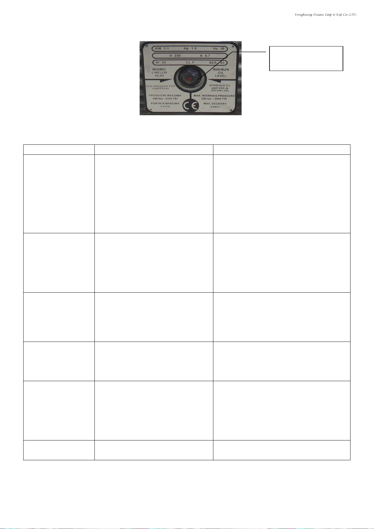
4.The power and frequency used should be compatible with that on the label, the power should be
grounded properly. Don’t operate it with low voltage.
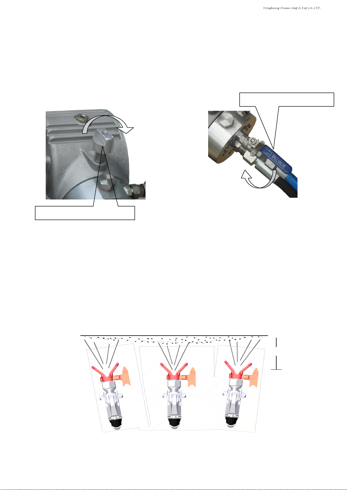
5. Make sure the all the fittings are tight, and hoses are connected properly before you use the machine.
6. To get a good performances, make sure the painting used is clean,, pure, use a filter bigger than 80.
7. The pressure adjustment can’t be more than 22.5MPa, if you need to replace the hose, it should be
from the manufacturer.
8. Never point the spray gun at yourself or anyone else.
9. Don’t use it to spray acid products, corrosion solvents or toxic chemicals. Never use with methylene
chloride.
10. Never eat anything or smoke during operation.
11. After use it, discharge the paint, release the pressure, then turn off the machine. Clear the
parts with cleanser.
12. Shut off the power during transportation, keep the motor and plug from water or paint. Keep the
machine clean and dry.
13. Use proper tools when to tight, adjust or maintain the machine with proper procedures, avoid damage
machine and injury of the user.
14. Never change the structure of the machine, always use the parts from the manufacturer.
Technical data
Item
Description
Model
SPX300
Power of motor
750W
Voltage/Frequency
110V/220V 50HZ/60HZ
Max. working pressure
210 Bar
Max. flow
3.0L/min
Max. tip
0.021”
Length of cable
5M
Total weight
37.5KG
Overall size
77×52×44cm
Item
Description
Model
SPX400
Power of motor
1.1KW
Voltage/Frequency
110V/220V 50HZ/60HZ
Max. working pressure
210 Bar
Max. flow
4.0L/min
Max. tip
0.025”
Length of cable
5M
Total weight
55KG
Overall size
86×62×53cm

2
Setting-up
1. Install the machine as the diagram
Figure 1
Caution: Open the inlet valve stem before the inlet valve is installed (Figure 2)
Figure 2
Put your finger into the inlet
valve, open the inlet valve
stem so it can move freely.
Inlet hose,
return hose
Pressure gauge
T-Connector
Spray gun,
hose
shelf

3
Preparation of the operation
Dip the inlet hose into water, turn on the motor, tighten the pressure valve(Figure 3, left) Clockwise,
Close the outlet valve clockwise when some water is sucked and comes out for outlet valve
(Figure3,right).When the pressure reaches up to about 20MPa, check if there is any leakage on the outlet
hose and other connections, if no, turn on the spray gun and try to spray (if there is no water in inlet hose,
hold the inlet hose, fill some water in it then turn on and off the motor for several times until water comes
out for the return hose)
Figure 3
Painting Operation
1. Keep about 350-400mm between the gun and the surface to be painted and also keep the gun
perpendicular to the surface.(Figure 4)
2. Move the spray gun before the trigger of gun is activated. Move the spray gun regularly during
operation. Release the trigger in the end of painting, then stop moving. The moving speed will be
varied with different painting, spraying pressure, and the distance between the spray gun and the
surface to be painted.
3. To keep the painting smooth, Paint the surface horizontally and vertically. The time difference
between two paintings depends on the paint used. Paint for second time after the first painting is
almost dry.
Figure 4
Tighten the Pressure valve
clockwise
350-400m
Start of painting
Normal painting
Stop of painting
Close the Outlet valve clockwise
顺时针关闭排出阀

4
Caution: if the tip is blocked during operation, turn the tip 180°anticlockwise for several times, it
will spray properly when it is turned back to the spraying Position.
Figure 5
Stop of operation
When the operation is finished, loosen the pressure valve (Figure 6. left), open the
outlet valve anticlockwise (Figure 6.right), release the pressure to zero, turn off the
motor, the motor will be burned if it is turned off without the pressure release
completely!(Figure 6)
Figure 6
Cleaning and Storage
1. Clean the sprayer as soon as the painting is finished, remove the paint left on the parts so it won’t get
hard and block anything, Use suitable cleanser instead of paint to clean the sprayer, spray it till all the
Spraying position
Cleaning position
Loosen pressure valve anticlockwise
Open outlet valve anticlockwise

5
paint comes out from pump body, hose and spray gun.
2. Clean the filter regularly. Remove the handle: take out the filter stem inside the handle and wash it,
then install and tighten it, replace it if there is any damage.
Figure 7.
3. If the painting is not smooth, check and clean the inlet filter, clean it after every use.
4. Check the fittings regularly to make sure there is no any leakage.
5. Check the oil inlet filter, prevent any other thing from the piston.(Figure 8)
Figure 8
6. After 3100 hours use of the machine, check if there is enough hydraulic oil and if it’s clean. (Check it
from the hole. Figure 9).If there is no enough oil but clean, add some; if the oil is not clean, replace it
immediately. Clean the oil tank with kerosene, then fill hydraulic oil till it is about 85% of the
capacity (No 46 hydraulic oil is recommended)
Handle
Washer
Removable connector
Filter
Remove the oil inlet filter
from the bottom and clean it.

6
Figure 9.
Problems and solutions
Problem
Cause
Solution
The machine doesn’t
start
1. The voltage is too low or power
supply used is not compatible
with the machine.
2. The Switch is disconnected
3. Pressure valve is not released or
some pressure inside it
4. Paint is solidified inside the
pump
1. Check the correct connection to the
power supply
2. Check if the switch is on
3. Loosen the pressure valve and open the
outlet valve, release pressure
4. Clean the pump.
The product doesn’t
suck paint
1.The suction filter is clogged
2. Inlet hose is air leaky.
3. The inlet valve is sticky.
4. The diaphragm is damaged
1. Clean or replace the filter
2. Check if the seal of inlet valve is
attached, the connection of inlet hose.
3. Refer to Figure 2, open the inlet valve
stem
4. Replace the diaphragm.
The machine sucks
but doesn’t reach the
pressure desired
1. The outlet valve is not closed
tightly, some returned flow.
2. Inlet valve or outlet valve is
dirty.
3. The diaphragm is damaged.
1. Close the outlet valve, no returned
flow
2. Remove the inlet valve or outlet valve
and clean it.
3. Replace the diaphragm.
The pressure drops
considerably when the
trigger is pressed
1. Tip is too big or damaged
2. The paint is too dense
3. Leakage in inlet hose
1. Replace the tip
2.Dilute the paint, if possible
3. Check the inlet hose
Normal pressure, but
paint is not
atomized, or
atomization is not
enough
1. The tip is clogged
2. The paint is too dense
3. The filter of spray gun is too fine
or clogged
4. The tip is not installed
properly
1. Refer to Figure 6 and clean it
2. Dilute the paint, if possible
3. Clean or replace the filter of spray gun
4. Refer to Figure 6, turn the tip to the
position of spraying,
The atomization is
imperfect
Tip is worn
Replace the tip
Before any check or replacement of parts, always turn off the machine and release
the pressure completely.
Check oil value through
it.

7
Figure 10.parts of pump body
No.
Description
Q’TY
No.
Description
Q’TY
1
Handle
1
7
Spray gun
1
2
Switch box
1
8
Hose
1
3
Motor
1
9
Valve block
1
4
Pump body
1
10
Inlet hose (Filter)
1
5
Pressure gauge
1
11
Returned hose
1
6
Shelf
1
1
2
3
4
8
7
6
5
7
6
9
8
10
5
11

8
Figure 11 Valve block assembled
No.
Description
Q’TY
No.
Description
Q’TY
12
Valve block
1
24
Seal on inlet valve
1
13
Valve block connector
1
25
Inlet valve stem
1
14
Outlet valve
1
26
Valve base
1
15
Outlet valve washer
1
27
Inlet valve body
1
16
Base of outlet valve
1
28
Holder of spring
1
17
Valve base body
1
29
Spring
1
18
Steel ball
1
30
Washer
1
19
Holder of steel ball
1
31
Nut
1
20
Spring
1
32
Sealing cover
1
21
Copper washer
1
33
Spray valve connector
1
22
Outlet valve nut
1
34
Spray valve
1
23
Inlet valve
1
35
Discharge connector
1

9
Figure 13.Spray gun assembled
No.
Description
Q’TY
No.
Description
Q’TY
36
Tip
1
44
Gun body
1
37
Seal
1
45
Gun filter
1
38
Valve seat
1
46
Gun handle
1
39
Valve stem
1
47
Washer
1
40
Fixing screw for trigger
2
48
Removable connector
1
41
Top leaver
2
49
Protector of trigger
1
42
Top block
1
50
Trigger
1
43
Nut
1
51
Tip seat
1
36
37
36
38
36
39
36
40
36
41
36
42
36
43
36
44
36
45
36
47
36
46
36
48
36
49
36
50
36
51
36

10
Figure 14. Diaphragm assembled
No.
Description
Q’TY
No.
Description
Q’TY
52
Diaphragm
1
54
Spring
1
53
Diaphragm holder
1
55
Nut
1
Figure 15. Inlet hose
No.
Description
Q’TY
No.
Description
Q’TY
56
Returned hose
1
58
Clamp
1
57
Inlet hose
1
59
Filter
1
56
57
58
59

11
Warranty
HYVST warrants all equipment referenced in this document which is manufactured by HYVST and bearing its name to
be free from defects in material and workmanship on the date of sale to the original purchaser for use. With the exception
of any special, extended, or limited warranty published by HYVST, HYVST will, for a period of twelve months from the
date of sale, repair or replace any part of the equipment determined by HYVST to be defective. This warranty applies
only when the equipment is installed, operated and maintained in accordance with HYVST’s written recommendations.
This warranty does not cover, and HYVST shall not be liable for general wear and tear, or any malfunction, damage or
wear caused by faulty installation, misapplication, abrasion, corrosion, inadequate or improper maintenance, negligence,
accident, tampering, or substitution of non-HYVST component parts. Nor shall HYVST be liable for malfunction,
damage or wear caused by the incompatibility of HYVST equipment with structures, accessories, equipment or materials
not supplied by HYVST, or the improper design, manufacture, installation, operation or maintenance of structures,
accessories, equipment or materials not supplied by HYVST.
This warranty is conditioned upon the prepaid return of the equipment claimed to be defective to an authorized HYVST
distributor for verification of the claimed defect. If the claimed defect is verified, HYVST will repair or replace free of
charge any defective parts. The equipment will be returned to the original purchaser transportation prepaid. If inspection
of the equipment does not disclose any defect in material or workmanship, repairs will be made at a reasonable charge,
which charges may include the costs of parts, labor, and transportation.
THIS WARRANTY IS EXCLUSIVE, AND IS IN LIEU OF ANY OTHER WARRANTIES, EXPRESS OR IMPLIED,
INCLUDING BUT NOT LIMITED TO WARRANTY OF MERCHANTABILITY OR WARRANTY OF FITNESS FOR
A PARTICULAR PURPOSE.
HYVST’s sole obligation and buyer’s sole remedy for any breach of warranty shall be as set forth above. The buyer
agrees that no other remedy(including, but not limited to, incidental or consequential damages for lost profits, lost sales,
injury to person or property, or any other incidental or consequential loss) shall be available. Any action for breach of
warranty must be brought within two (2) years of the date of sale.
HYVST MAKES NO WARRANTY, AND DISCLAIMS ALL IMPLIED WARRANTIES OF MERCHANTABILITY
AND FITNESS FOR A PARTICULAR PURPOSE, IN CONNECTION WITH ACCESSORIES, EQUIPMENT,
MATERIALS OR COMPONENTS SOLD BUT NOT MANUFACTURED BY HYVST. These items sold, but not
manufactured by HYVST (such as electric motors, switches, hose, etc.), are subject to the warranty, if any, of their
manufacturer. HYVST will provide purchaser with reasonable assistance in making any claim for breach of these
warranties.
In no event will HYVST be liable for indirect, incidental, special or consequential damages resulting from HYVST
supplying equipment hereunder, or the furnishing, performance, or use of any products or other goods sold hereto,
whether due to a breach of contract, breach of warranty, the negligence of HYVST, or otherwise

12
All written and visual data contained in this document reflects the latest product information
available at the time of publication. HYVST reserves the right to
make changes at any time without notice.
YONGKANG OCEAN IMP & EXP CO.,LTD.
ADD: 23 F, Jinsong Mansion, Headquarter Center,
Yongkang City, Zhejiang Province, China.
Tel:+86 579 87172043
Fax:+86 579 87172042
Http:// www.hyvst.com
www.sprayertech,com
This manual suits for next models
1
Table of contents