I.D. Systems Vehicle Asset Communicator User manual

I.D. SYSTEMS, INC.
VAC™ – Vehicle Asset Communicator™
A Wireless Fleet Management Device
VAC
User’s Guide
Version 3.1.x
VAC™ – A WIRELESS FLEET MANAGEMENT DEVICE
VAC – User’s Guide
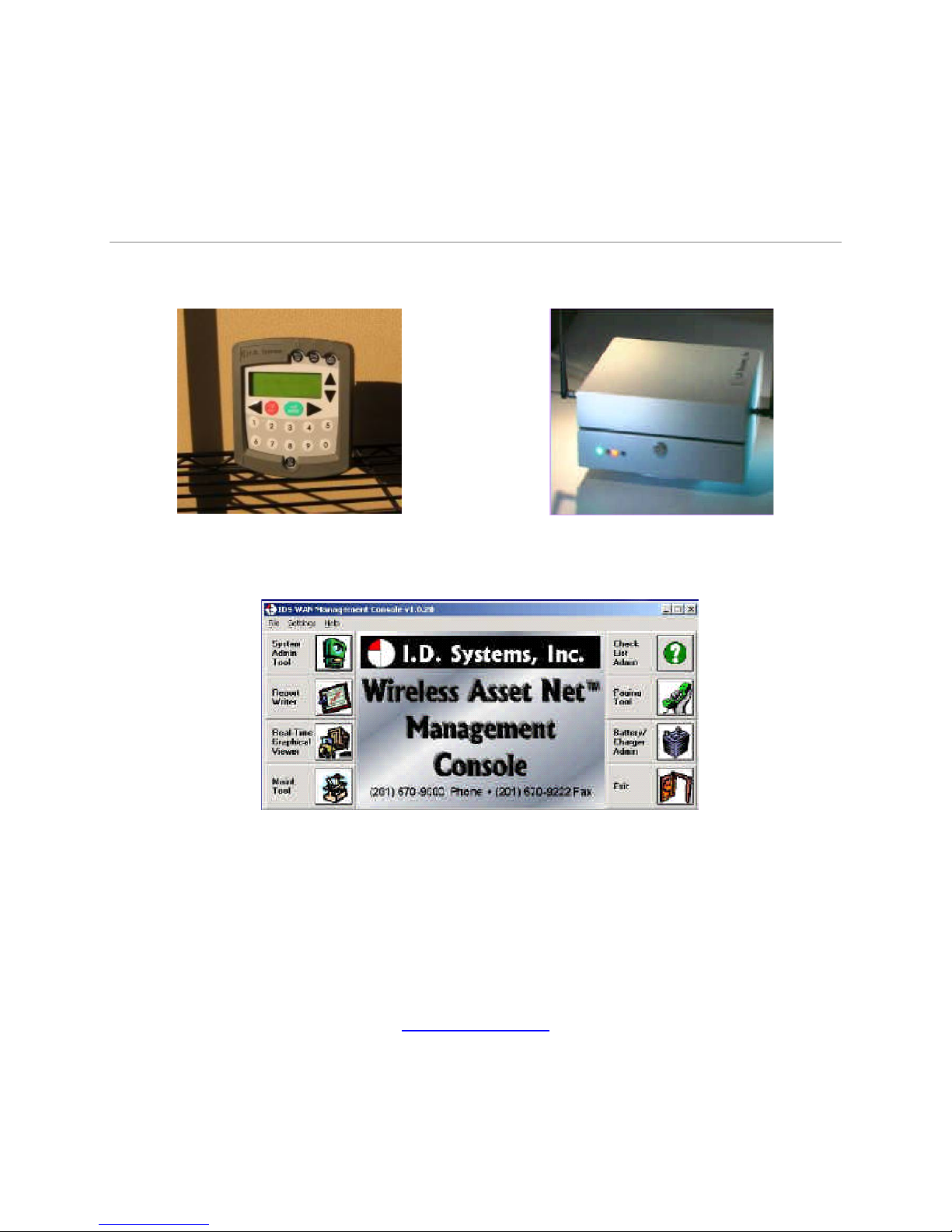
VAC™ IDS Gateway™
IDS WAN Console™
©I.D. Systems, Inc.
1 University Plaza • 6th Floor
Hackensack, NJ 07601
Phone 201.996.9000 • Fax 201.996.9144
www.id-systems.com

Preface
This manual is a user’s guide for the VAC (Vehicle Asset Communicator), a Wireless Fleet Management
Device developed by I.D. Systems, Inc. This guide provides the instruction necessary for someone to
install, operate and maintain the VAC device in a vehicle. Note: This user’s guide may change without notice due to
enhancements or changes to VAC.
Related Documents
Vehicle Survey (Doc. #: 026-1000-01)
Publication History
Version Date Changes
2.5.x 9.18.02 Initial
2.6.x 10.25.02 New Modules: Seatbelt monitor & Battery rotation, new
installation screens and color coded connector labels
2.7.x 01-03-03 Add Ext Reader Test, Ext LED Test, Security Features
2.8.x 08-07-03 Add Critical OSHA Shutdown, Blank VAC In Motion
3.0.x 11-03-03 Now Using New Enclosure
3.1.x 03-11-04 O/T versions for new enclosure
Disclaimer and Limitation of Liability
I.D. Systems, Inc. assumes no responsibility for any damage or loss resulting from the use of its products
or services. I.D. Systems assumes no responsibility for any loss or claims by third parties, which may arise
through the use of its products or services.
The information disclosed herein is the exclusive property of I.D. Systems and no part of this information
may be reproduced or transmitted in any form or by any means including electronic storage, reproduction,
execution or transmission without the prior written consent of I.D. Systems. The information contained
in this document is subject to change without notice and should not be construed as a commitment by
I.D. Systems unless such commitment is expressly given in writing.

FCC Compliance Statement
Compliance Statement (Part 15.19)
This device complies with Part 15 of the FCC Rules. Operation is subject to the following two
conditions:
1. This device may not cause harmful interference, and
2. This device must accept any interference received,
including interference that may cause undesired operation.
Warning (Part 15.21)
Changes or modifications not expressly approved by the party responsible for compliance could void the
user’s authority to operate the equipment.
Compliance Statement (Part 15.247)
This device complies with Part 15.247 of the FCC rules. Operation is subject to the following condition:
To comply with FCC’s RF exposure limits for general population/uncontrolled exposure, the antenna(s)
used for this transmitter must be installed to provide a separation distance of atleast 20cm from all
persons and must not be co-located or operating in conjunction with any other antenna or transmitter.

TableofContents
I.D. Systems, Inc. One University Plaza, Hackensack, NJ 07601 000-0144-01
Table of Contents
TABLE OF CONTENTS.........................................................................................................................................................................................5
INTRODUCTION......................................................................................................................................................................................................7
SYSTEM OVERVIEW................................................................................................................................................................................................ 7
INSTALLATION .......................................................................................................................................................................................................9
WARNINGS............................................................................................................................................................................................................9
STANDARD HARDWARE FOR INSTALLATION.................................................................................................................................................... 9
TOOLS REQUIRED FOR INSTALLATION (NOT SUPPLIED)............................................................................................................................. 9
SYSTEM CONNECTIONS OVERVIEW ................................................................................................................................................................. 10
INSTALLATION SUMMARY................................................................................................................................................................................... 10
BEFORE STARTING THE INSTALLATION.......................................................................................................................................................... 10
INSTALLING THE VAC (AND OPTIONAL ID READER)................................................................................................................................... 11
Selecting the VAC Mounting Location.............................................................................................................................................................. 11
Mounting the VAC............................................................................................................................................................................................. 11
INSTALLING VAC-TO-PCM HARNESS............................................................................................................................................................ 12
Vehicle Cable Harness......................................................................................................................................................................................12
Selecting the System’s Power and Ground Connections.................................................................................................................................. 12
FINISHING THE INSTALLATION.......................................................................................................................................................................... 13
System Configuration........................................................................................................................................................................................13
STANDARD VAC OPERATION.......................................................................................................................................................................14
VAC OVERVIEW .................................................................................................................................................................................................... 14
GENERAL OPERATION.......................................................................................................................................................................................... 15
BASIC OPERATION:LCD, KEYPAD,ID READER AND LEDS....................................................................................................................16
VAC Display and Keypad Basics......................................................................................................................................................................16
ID Reader..........................................................................................................................................................................................................16
Menu Selection Mode........................................................................................................................................................................................ 16
Digit Entry Mode............................................................................................................................................................................................... 17
ACCESS CONTROL (ALL USERS): LOGGING ON AND OFF THE VEHICLE ...............................................................................................18
Access Control Overview.................................................................................................................................................................................. 18
Logging onto the VAC....................................................................................................................................................................................... 19
Denial of Login .................................................................................................................................................................................................21
NOTE: Repeated failure to log into the VAC will trigger an alert on the ARDCS which can be emailed or sent by pager to specified
personnel (See ARDCS User’s Guide)............................................................................................................................................................. 22

VACUser’sGuide
I.D. Systems, Inc. One University Plaza, Hackensack, NJ 07601 000-0144-01
Logging Off of the VAC.....................................................................................................................................................................................23
ELECTRONIC OSHA SAFETY CHECKLISTS (ALL USERS)..........................................................................................................................23
OSHA Question Mode.......................................................................................................................................................................................24
Critical OSHA Shutdown (Optional)................................................................................................................................................................26
TWO-WAY TEXT PAGING (ALL USERS).......................................................................................................................................................... 26
Viewing and Responding to Text Pages............................................................................................................................................................ 27
VEHICLE UTILIZATION MONITORING (ALL USERS)..................................................................................................................................... 29
MOTION SAFETY FEATURE (OPTIONAL –STANDARD AND MASTER USERS)........................................................................................ 30
BATTERY ROTATION (OPTIONAL MODULE -ALL USERS).......................................................................................................................... 30
Battery Request:................................................................................................................................................................................................ 31
Battery Validation:............................................................................................................................................................................................ 32
Battery Request Troubleshooting:.................................................................................................................................................................... 33
SECURITY MODULE (OPTIONAL MODULE -ALL USERS)............................................................................................................................ 33
GRANTING TEMPORARY ACCESS (MASTER USERS)................................................................................................................................... 33
APPENDIX A............................................................................................................................................................................................................35
ELECTRICAL............................................................................................................................................................................................................ 35
MEMORY/OTHER....................................................................................................................................................................................................35
COMMUNICATION.................................................................................................................................................................................................. 35
USER INTERFACE.................................................................................................................................................................................................. 36
ENVIRONMENTAL ..................................................................................................................................................................................................37
MOUNTING..............................................................................................................................................................................................................37
APPENDIX B............................................................................................................................................................................................................38
VAC™ ERROR CODE GUIDE ..............................................................................................................................................................................38
Error Code: E3301 ...........................................................................................................................................................................................38
APPENDIX C............................................................................................................................................................................................................39
WARRANTY INFORMATION.................................................................................................................................................................................. 39
Limited Warranty .............................................................................................................................................................................................. 39
This Warranty Does Not Cover: .......................................................................................................................................................................39
General Provisions: ...........................................................................................................................................................................................40
To Get Warranty Service or Returned Material Authorization: ....................................................................................................................... 40

Introduction
I.D. Systems, Inc. One University Plaza, Hackensack, NJ 07601 000-0144-01
Introduction
This manual is a user’s guide for the VAC (Vehicle Asset Communicator), a Wireless Fleet Management
Device developed by I.D. Systems. This guide will introduce the reader to the VAC and to I.D. Systems’
Fleet Management solution. In addition, this guide also includes information about VAC installation
procedures, installation options, operator instructions, maintenance procedures, and troubleshooting. The
owner and user of a VAC can use this guide to understand how a VAC works and how to interact with it.
The Introduction section covers general information about the IDS Fleet Management System, and what
part the VAC device plays in the system. Users of the IDS Fleet Management System should familiarize
themselves with this information to better understand the detailed instructions in this guide.
The Installation section provides detailed procedures and guidelines for hardware installation.
Electricians, mechanics or maintenance persons responsible for VAC installation or troubleshooting
should familiarize themselves with this hardware installation process. This will allow them a better
understanding of the interface between the VAC and the vehicle being managed. In addition, those who
perform vehicle maintenance will better understand the implications of parts replacement or rewiring.
Finally, VAC troubleshooting is more easily understood with an understanding of hardware installation
procedures and guidelines. In order to complete VAC installation, maintenance user software, covered in
the VAC Operation section is required.
The Standard VAC Operation section explains how the user interacts with the VAC user interface
(keypad, display and ID reader). As a mini-computer, the VAC is an interactive device requiring an
operator to interact with it. Standard operators (vehicle drivers) must familiarize themselves with the
section on Basic Operation, Access Control, Electronics, OSHA Checklists, and Two-Way Text Paging,
either through reading the Guide, or through hands-on training. Floor supervisors with special system
privileges (Master Users) should also become familiar with the Master User features.
The appendices include additional information for those who have purchased or who maintain the VAC.
Appendix A details the physical specifications of the system, which is useful for those who wish to
understand how the VAC will work in specific environments. Appendix B is a troubleshooting guide for
maintenance personnel to handle issues with the VAC that may arise through installation or operation.
Finally, Appendix C covers warranty information for those who have purchased the VAC product.
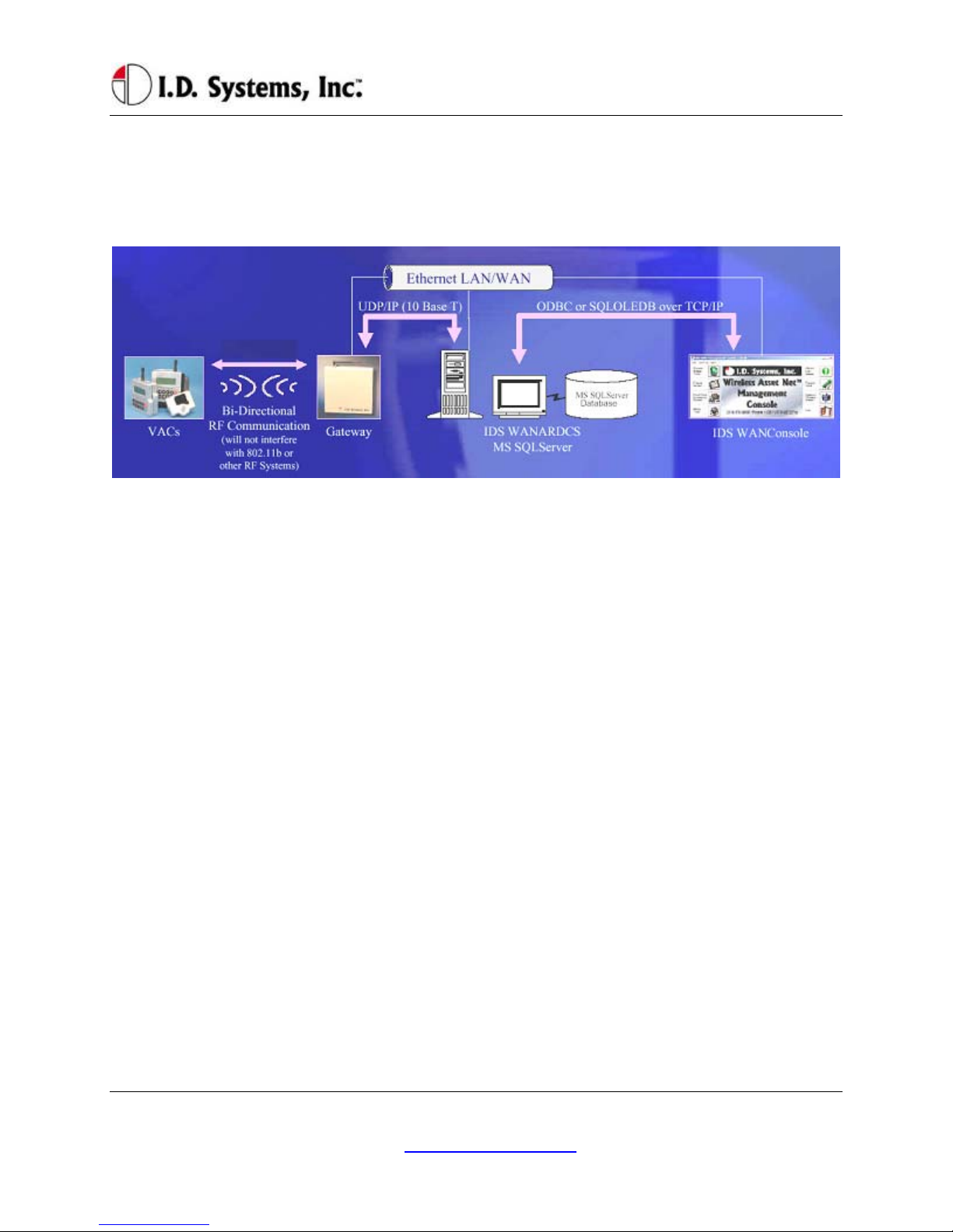
System Overview
The VAC is part of a comprehensive fleet management solution, integrating access control, vehicle
VACUser’sGuide
I.D. Systems, Inc. One University Plaza, Hackensack, NJ 07601 000-0144-01
monitoring, safety, maintenance and communication technology in an industrial vehicle. Within the VAC,
a processor is integrated with an RF transceiver and vehicle interface and runs an embedded computer
application. Information about the attached vehicle is communicated from the VAC over the wireless
infrastructure of Gateways™, to I.D. Systems software (refer to the system diagram in Figure 1).
Figure 1: IDS Fleet Management System Diagram
The VAC device both sends and receives information, such as access control updates, pages, updated
configuration settings, and scheduled maintenance event information, and interacts with the vehicle’s
driver using a keypad, display, and optional ID readers.

Installation
I.D. Systems, Inc. One University Plaza, Hackensack, NJ 07601 000-0144-01
Installation
WARNINGS
* Please read this document in its entirety
BEFORE performing any installation. *
* Please disconnect main vehicle battery
BEFORE performing any installation. *
Standard Hardware for Installation
The standard components of the VAC system are installed on every vehicle type (Industrial Electric and
Internal Combustion). The following is a list of standard equipment that is required to install each VAC
system:
900-0144-02: Universal Vehicle Asset Communicator (VAC)
810-0113-0x: VAC-to-PCM Cable
835-0121-01 and -03: Mounting Hardware Assortments
825-0111-01: Vehicle Asset Communicator Mounting Bracket
During hardware installation and system configuration, a test sheet must be filled out and sent (via mail or
fax) to I.D. Systems, Inc. to certify that the installation was performed correctly. The test sheet is
provided with the hardware.
For technical support, contact I.D. Systems, Inc.:
By Phone: (201) 996-9000
By Fax: (201) 996-9144
By email: [email protected]
Tools Required for Installation (Not Supplied)
In order to install the standard components of the VAC system, certain tools are required. The VAC is
mounted rigidly to each vehicle, thus requiring mounting hardware (supplied in Mounting Hardware
Assortment kits) and requiring holes to be drilled. In addition to mechanical mounting, some wiring and
electrical testing must be performed. Therefore, wire strippers and simple electrical test equipment are
required.
MOLEX RHT-1991 Ratchet tool or equivalent

VACUser’sGuide
I.D. Systems, Inc. One University Plaza, Hackensack, NJ 07601 000-0144-01
Minimum ¼” chuck drill
¼” drill bit
1 ¼” or 1 ½” hole saw
#10 socket and ratchet (or open-end wrench)
Medium sized slotted and Phillips screwdrivers
Wire stripper
Multimeter and test lead assortment
Note: The system is shipped with a set of hardware used to install the system on a vehicle (Mounting
Hardware Assortment kits). The hardware should accommodate most vehicle types. The hardware kit is
specified for high vibration industrial applications. I.D. Systems highly recommends using the MOLEX
RHT-1991 Ratchet tool (or equivalent) for crimping terminals. If using a different tool, I.D. Systems will
bear no responsibility for resulting installation failures.
System Connections Overview
Figure 2: System Diagram
1. VAC: Vehicle Asset Communicator. User interface and intelligent industrial control device.
Operators read the display and use the keypad to interact with the vehicle control system. A two-
way radio transceiver is embedded within the VAC.
2. VAC-to-PCM Cable: Cable that connects the VAC to the vehicle’s Power and Control system.
This cable must route from the VAC mounting location (driver area) to the vehicle (typically the
engine/motor compartment).
Installation Summary
The installation must be performed in the order that follows:
Installing the VAC (with optional ID reader) [Items 1, 2]
Configuring the VAC using On-Screen Display
Before Starting the Installation
Before starting a VAC installation, make sure that all required tools and equipment and the Installation

Installation
I.D. Systems, Inc. One University Plaza, Hackensack, NJ 07601 000-0144-01
Verification test sheet are available. If not, do not proceed with installation. If all equipment is
available, record the following on the installation sheet:
The VAC serial number
Installing the VAC (and optional ID Reader)
The VAC contains the driver’s user interface to the system and also contains the embedded fleet
management software and RF capability. The VAC, therefore, must be mounted in a location that is
convenient for operator access (to the keypad, LCD and optional ID reader) and that is optimized for RF
performance. The VAC is wired into the vehicle. Therefore, selecting the proper location and verifying
correct installation is important to ensure correct functionality.
Selecting the VAC Mounting Location
Notes:
The VAC is mounted to the vehicle using the supplied VAC Mounting Bracket (modifications or
custom brackets must be approved by I. D. Systems in order to ensure proper functionality).
Procedure:
Select a location on the dash area of the vehicle to mount the VAC.
oThe operator of the vehicle should be able to view the VAC’s display and access the
keypad and optional ID reader while sitting in the vehicle.
oThe VAC should not obscure the operator’s line of sight or accessibility to the vehicle.
oThe VAC display should not be obscured.
oThe VAC’s antenna should be as far away from the vehicle’s chassis as possible (having
the antenna close to the metal of the vehicle [less than 3”] attenuates the unit’s RF
communications).
oThe VAC should be securely affixed to the vehicle and is not adjustable for different
operator heights.
Select the location on the vehicle to which the bracket should be bolted or welded.
Mounting the VAC
If mounting with bolts, use the bracket as a template to drill holes in the vehicle for mounting the
VAC bracket. The bracket has to be secured to the vehicle by at least two bolts. Make sure that
nothing can be damaged on the vehicle while drilling or welding.
If the VAC-to-PCM cable has to run through the dash of the vehicle, drill using a 1¼” hole saw.
Assemble the VAC onto the Bracket.
If the VAC-to-PCM cable runs through the vehicle’s dash, insert a Grommet (supplied) in the
hole to prevent the cable from being damaged.

VACUser’sGuide
I.D. Systems, Inc. One University Plaza, Hackensack, NJ 07601 000-0144-01
Using the attached hex key tighten the hex nuts to secure the swivel points. The bracket is not
supposed to be adjustable. Failure of tightening the hex nuts will result in assembly failure.
Attach the 9-pin circular connector of the VAC-to-PCM cable (Item 4) to the circular connector
on the back of the VAC.
Route the VAC-to-PCM cable through the hole in the VAC mounting bracket and route all the
way to the vehicle interface location.
oUse the vehicle’s pre-existing cable-routing channels (where other cables are also run
throughout the vehicle) to prevent the cable from being damaged during vehicle use or
maintenance.
Installing VAC-TO-PCM Harness
The VAC-TO-PCM Harness connects the VAC to the vehicle. Through the harness, the VAC system
will get power from the vehicle, and have the ability to receive commands from the vehicle via the I.D.
Systems Serial Data Interface (IDSY SDI) protocol. Installation of this cable must be performed
according to the instructions below for the VAC system to operate properly.
Vehicle Cable Harness
Cable Pin-Out:
Pin Color Signal Name Comments
1 RED POWER Power (+)- TO REGULATED 6.5 VDC
2 BLACK POWERRTN Power return (-) - TO 6.5 VDC RETURN
3 WHITE ISEN(-) IDSY SDI SIMO (OPTIONAL)
4 GREEN RELAYIN IDSY SDI SOMI (OPTIONAL)
5 ORANGE RELAYOUT IDSY SDI SCLK (OPTIONAL)
6 BLUE VSEN1(-) IDSY SDI INT_NCS (OPTIONAL)
7 WHITE/
BLACK
VSEN1(+) IDSY SDI INTRPT (OPTIONAL)
8 RED/
BLACK
VSEN2(+) IDSY SDI WAKEUP (OPTIONAL)
9 RED/
BLACK
N/C NO CONNECT
Selecting the System’s Power and Ground Connections
Notes:

Installation
I.D. Systems, Inc. One University Plaza, Hackensack, NJ 07601 000-0144-01
The system requires an uninterrupted, regulated 6.5 VDC supply from the vehicle. The
supply should be continuous regardless of the condition of the vehicle. The only time the supply
is discontinued is when the vehicle’s battery is unplugged.
The interface should be the cleanest possible power source, free from noise and damaging voltage
spikes.
The current draw of the system in normal mode at 6.5 VDC is approximately 0.25 Amperes
Finishing the Installation
System Configuration
In order to complete the installation of the VAC system on a vehicle and to ensure proper operation of
the system.

VACUser’sGuide
I.D. Systems, Inc. One University Plaza, Hackensack, NJ 07601 000-0144-01
Standard VAC Operation
VAC Overview
The VAC device is the vehicle component of a comprehensive fleet management system provided by I.D.
Systems. The VAC incorporates a highly customized computer application, a two-way wireless
communications port, and a vehicle power and data interface. The complete fleet management solution
also requires other system elements: wireless infrastructure devices, termed Gateways, a server computer
running the ARDCS software, and at least one computer running WAN Console software. Combined,
the IDS Fleet Management solution provides the following major benefits:
Automated compliance with OSHA rules
Electronic, paperless OSHA checklists
Automated vehicle utilization analysis
Operator accountability
Real-time vehicle location tracking
Enhanced maintenance efficiencies
Significant cost savings
To achieve the above benefits, the VAC is designed to implement several critical Fleet Management
functions, including:
Driver OSHA checklist interface – allowing drivers to identify and communicate vehicle status by
answering vehicle-specific safety questions
Two-way paging – option that allows drivers to receive and respond to messages sent from plant
computers
Vehicle Utilization Monitoring – If the vehicle interface permits, provides accurate fleet
information through motion sensing, lift sensing, log-on time, and battery monitoring
Maintenance Management - predictive forecasting and driver notification of scheduled
maintenance
Access Control – tracks the current operator using the equipment. If the vehicle interface
permits, also prevents unauthorized operators from driving vehicles, using individual driver IDs
instead of vehicle keys
As a radio frequency (RF) and computing device, the VAC utilizes the most robust communication
protocol in the industry to ensure that all relevant data is communicated with the rest of the system.

Installation
I.D. Systems, Inc. One University Plaza, Hackensack, NJ 07601 000-0144-01
When in range of IDS Gateways, the VAC will:
Display an ‘in-range’ indicator, letting the driver know that information can currently be
communicated
Send any stored data, verifying receipt through a robust confirmation process
Synchronize with the most up-to-date access control information (add, delete or modify
authorized driver information)
Receive any updates to vehicle settings, such as battery and impact thresholds, or OSHA
questions
Update the vehicle’s location, and, if necessary, send a location update to the system
General Operation
Three different groups of operators will interact with the VAC – the standard driver, the Master User
driver, and the maintenance/installation user.
The standard driver will perform certain basic functions with the VAC (for Standard Driver Instructions,
see Basic Operation: LCD, Keypad, ID Reader on page 16). These features are:
Logging onto the vehicle to gain access
oIdentifying himself/herself using an ID (either by typing the ID or through an ID device)
oVerifying his/her identity using a PIN (if required)
Logging off of the vehicle prior to leaving the vehicle unattended
Answering OSHA-required safety questions
Reading, responding to, and deleting pages (optional)
Identifying low vehicle battery condition
The Master User driver can perform the same basic functions with the VAC (For Master User
Instructions, see Granting Temporary Access (Master Users) on page on page 33), as well as:
Logging onto all vehicles
Granting temporary access to a currently unauthorized standard driver
The Maintenance/Installation User can perform the same functions as a Master User driver as well as
VAC configuration (For Maintenance Instructions, see Error! Reference source not found. on page
Error! Bookmark not defined.). The additional features include:
Assigning the Vehicle ID to the VAC
Enabling and disabling access control
Configuring the VAC sensors for motion sensing, lift sensing, and battery sensing
VACUser’sGuide
I.D. Systems, Inc. One University Plaza, Hackensack, NJ 07601 000-0144-01
Verifying impact sensing
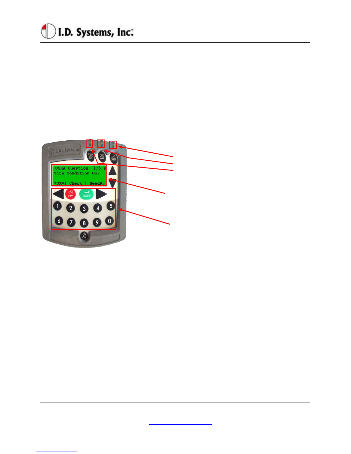
Basic Operation: LCD, Keypad, ID Reader and LEDs
The VAC incorporates a robust 20-key keypad and a 20-by-4 character display that is backlit for 15
seconds when a key is pressed. In addition, certain units are equipped with identification device readers
(proximity card, magnetic card, 1-wire memory chip such as an iButton, or smart card). The operator
interacts with the VAC using these devices in the following way:
VAC Display and Keypad Basics
LEDs:
•OSHA not filled
•Incoming, unread page
•Access Enabled
LCD Display: (Backlit, 20-by-4 characters)
Screen Contents: To interact with the driver, the VAC uses
a backlit display. The same display is used in Menu
Selection Mode, Digit Entry Mode and Pager Mode.
Keypad: (20-Key, Rugged with Tactile Keys)
20-Key Keypad: The keypad allows the driver to make
menu selections (in Menu Selection Mode), type digits (in
Digit Entry Mode) and review and respond to pages (in
Pager Mode).
ID Reader
VACs may be equipped with ID Readers for the quick and secure entry of driver ID numbers. ID
readers are mounted in the VAC. The ID reader is used:
During the Access Control log-in process (to quickly enter the driver ID)
During the Access Control log-off process (to quickly log off the current driver)
During the Grant Temporary Access process (to enter the ID of the temporarily-authorized
driver)
Menu Selection Mode
Most screens on the VAC involve reading displayed text and selecting from menu options. These screens
contain four major components:
Screen Title: The top line of the display. Indicates the title or subject of the current screen.
¥ (Yen): This symbol is the in-range indicator for the VAC. The faster it blinks, the closer the

Installation
I.D. Systems, Inc. One University Plaza, Hackensack, NJ 07601 000-0144-01
VAC is to a Gateway. When in range of a Gateway, a VAC will download any required data and
will attempt to upload data. The VAC will continue to function and record data, however, when
not in range of a Gateway.
Screen Data: The second and third lines contain screen data. If there are more than two lines of
screen data, the up and down arrows (keys 2 and 7) must be pressed to scroll through the data.
Menu Options: The bottom line of screen. Available menu options are listed, separated by ⎢
characters.
oAsterisked *selection* shows response that will be selected by pressing ENTER key
oChange *selection* by pressing right arrow or left arrow keys
o>> indicates more responses available by scrolling with right arrow key
o<< (not shown) indicates more responses available by scrolling with left arrow key
oAfter highlighting *selection*, press ENTER key to confirm selection and proceed
automatically to the next screen.
Keypad: (20-Key, Rugged
with Tactile Keys)
Up-arrow and down arrow
scroll through screen data.
Left-arrow and right arrow
scroll through menu options
ESC: Return to previous
screen
ENTER: Confirm the
currently highlighted
selection.
LCD Display: (Backlit, 20-by-4
characters)
Screen Title: First line indicates title or
subject of current screen
¥ –‘Yen:’ In-range indicator. The faster
this blinks, the better the receipt of data
from Gateways.
Screen Data: Second and third lines
contain screen data.
Menu Options: Appear along the bottom
line of screen, separated by ⎢characters
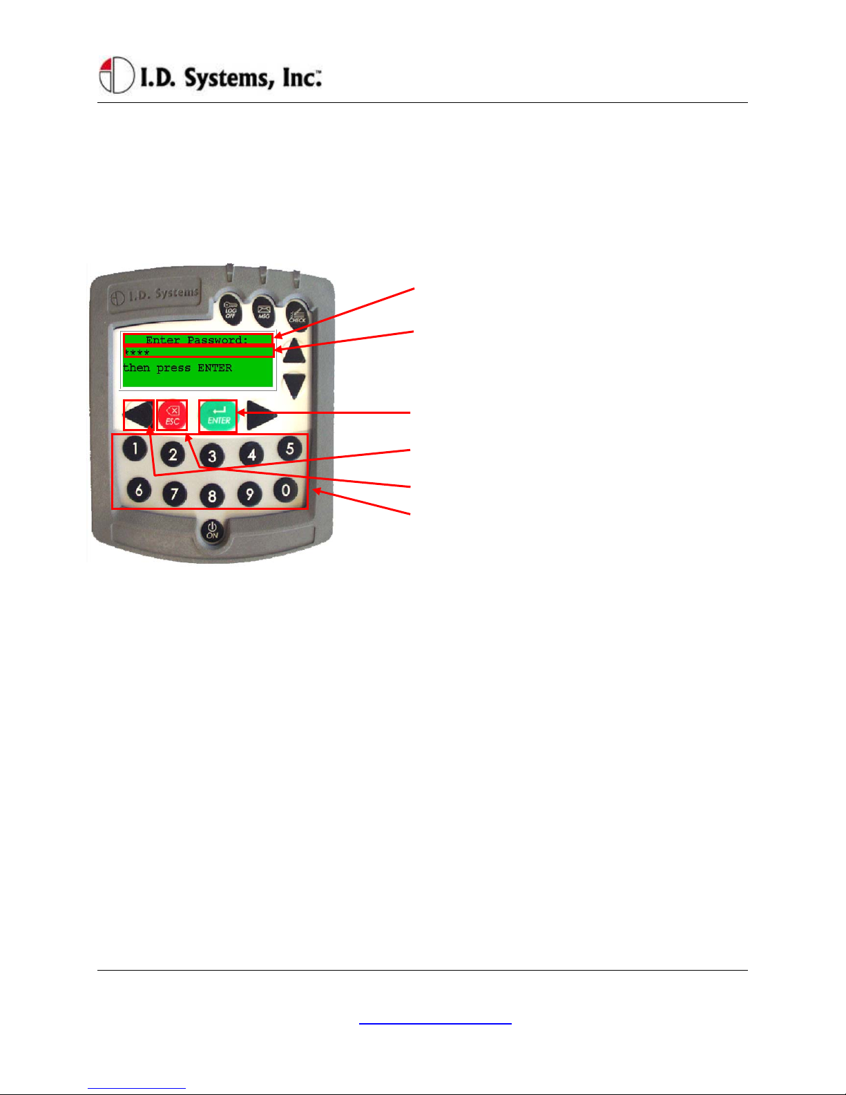
Digit Entry Mode
For VAC screens, which ask for a numerical entry, the digit entry mode screen will appear. These screens
contain two major components:
Screen Title: The top line of the display. Indicates the title or subject of the current screen.
Numerical Data: The second line contains the numerical data. A default value will appear of the
correct data length when entering this screen.
oA blinking cursor shows the current cursor location for data entry.
oEnter digits by typing desired number, 0-9 using the keypad
oBackspace using the Left Arrow key.
oPressing ESC key will return to the previous screen.
oPress ENTER key to confirm numerical entry. The entry will consist of each digit
VACUser’sGuide
I.D. Systems, Inc. One University Plaza, Hackensack, NJ 07601 000-0144-01
displayed on the screen (typed as well as default digits, EXACTLY AS THEY APPEAR
ON THE SCREEN. For example, if ‘0000’ appears on the screen, and the user presses 2
then 1, the screen will read ‘2100’. In this case, 2100 will be submitted if the ENTER key
is pressed.).
oTherefore, to keep the default entry without making a change, simply press ENTER
without pressing any digits.
o
–LCD Display: (Backlit, 20-by-4 characters)
Screen Title: First line indicates title or subject of current
screen
Numerical Data: Second line contains numerical data
(Note: Password screen uses asterisks (*) to hide entered
data). Third line may contain helpful information.
Keypad: (20-Key, Rugged with Tactile Keys)
ENTER: Press this key to confirm the current entry
Left Arrow: Press this key to back up one space
ESC:Press this key to return to previous screen
0-9: Press these keys to enter a digit at the current cursor
location
Access Control (All Users): Logging on and off the Vehicle
Access Control Overview
One feature of the VAC is to prevent unauthorized access to the VAC, and, optionally, the vehicle. Each
VAC is assigned a vehicle number (often similar to the number marked on the side of the vehicle), and
that number has an associated authorization list that contains valid drivers and, for each driver, the times
of day and days of week for which they are allowed drive that particular vehicle. The VAC stores the
authorization list and is updated, if changes have been made, when in radio range of any Gateway.
In order for vehicle access control to prevent vehicle access, it is required that the vehicle comply with the
I.D. Systems Serial Data Interface protocol. For a compliant vehicle, unless the VAC is in ‘bypass mode,’
all Standard, Master User and Maintenance drivers must log into the VAC to gain access to the vehicle.
Once authorized, the driver may also be required to use a key to start or drive vehicle.
Whether or not access is controlled by the VAC, once logged onto (or ‘assigned to’) a VAC, the driver is
Installation
I.D. Systems, Inc. One University Plaza, Hackensack, NJ 07601 000-0144-01
responsible for the vehicle. Therefore, it is imperative that drivers do not leave assigned vehicles
unattended. If, however, a driver forgets to log off, the VAC is configured to ‘time out’ after a
configurable period of non-use. (system-wide default: twenty minutes, changed via the ARDCS –
Beacon). While this idle-timeout feature is a fail-safe, it will not prevent another driver from taking an
assigned vehicle during the time prior to the time-out. In addition, the idle-timeout feature may be
disabled for the entire system (via ARDCS Beacon) or set on a vehicle a vehicle-by-vehicle basis (via
System Admin Tool – Modify Vehicle – Advanced Settings).
Drivers identify themselves to the VAC for access to a vehicle using their Access ID number. To enter
that number, the driver either uses the keypad or an ID device (such as a proximity card, smart card,
magnetic card, or iButton). The ID method is usually chosen to match that which the driver already uses
for other access control purposes (such as doorway entry). The Access ID number may not be the same
as the employee ID number, depending on the methodology used at the facility. The Access ID numbers
are linked to the drivers using the Console’s System Admin Tool.
Driver IDs are associated with VAC IDs using groups. Authorization groups are created using the
Console’s System Admin Tool. Both vehicles and drivers are added to groups. When a driver belongs to
the same group as a vehicle, and if that group is granted an authorization for the current time of day/day
of week, then the driver may gain access to the vehicle. All driver, group and authorization time
information is configured with the System Admin Tool and stored on each VAC. Initial configuration
and ongoing updates occur wirelessly and automatically, when VACs are in range of Gateways.
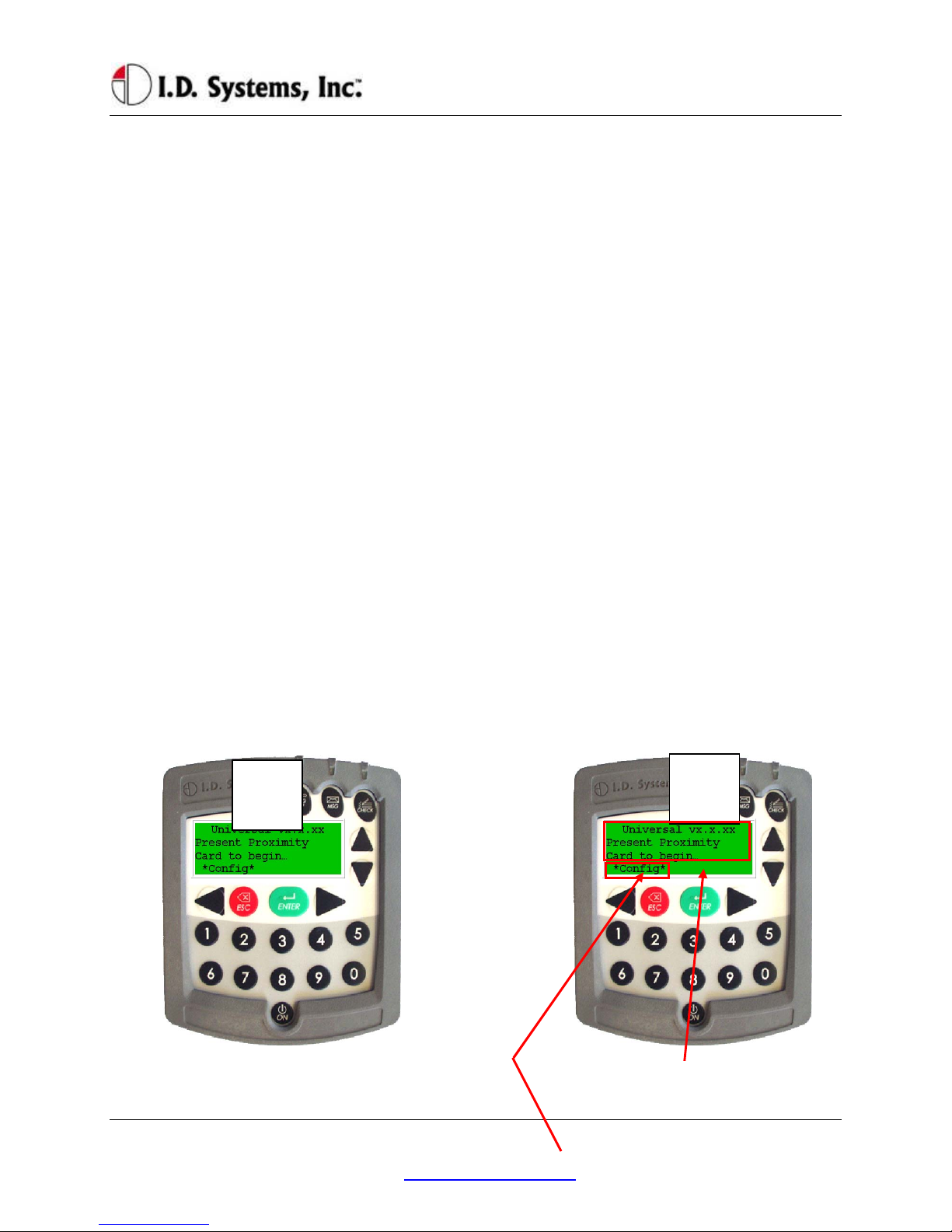
Logging onto the VAC
If VAC screen is blank (only on certain internal
combustion vehicles), turn vehicle ignition key on. Follow instructions on how to enter driver’s ID
(either by typing driver ID or presenting an ID
card – proximity, magnetic stripe, smart-card or
1 2

VACUser’sGuide
I.D. Systems, Inc. One University Plaza, Hackensack, NJ 07601 000-0144-01
iButton)
*Config*: (if applicable) Allows a Maintenance
User to log in without an ID card; for keypad-
only systems, this menu option does not appear.
A PIN code will then be requested (if the system is
configured to have PIN). Use the numeric keys to
enter PIN. After entering PIN (hidden by ****
characters for security), press ENTER key. If no PIN
is required, press ENTER when prompted with default
PIN of 0000.
If driver ID and PIN are authorized, vehicle
start-up will be enabled and driver can use
vehicle. VAC screen will prompt driver to
complete OSHA vehicle inspection checklist. If
driver is not authorized, see Denial of Login on
page 21.
3 4
This manual suits for next models
1
Table of contents
Popular Automobile Accessories manuals by other brands

FVC
FVC Sprinter Side Ladder installation guide

Easee
Easee Base 1-Way USER GUIDE / INSTALLATION GUIDE

Kargo Master
Kargo Master 4081M installation guide

Fastway
Fastway ONESTEP XL Instructions for setup

Voxx Electronics
Voxx Electronics ACA800 Installation & owners guide

AKE
AKE PB-HC2 Additional instructions


