ISOCON-6 USERS GUIDE
4.1.5 Thermocouple Input:
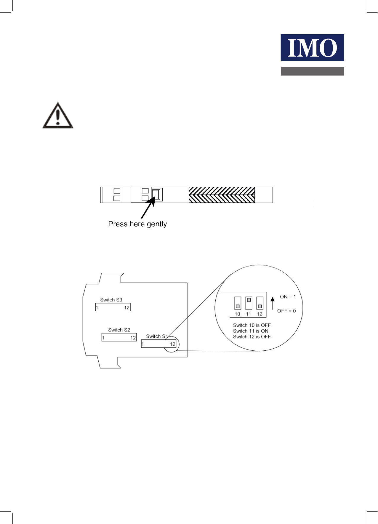
Select the range from the table below and set Switch S1 to the required values.
Then select the required setting from the table below for switch S2
Please note that PC Software is available to provide information on switch settings for your input and output requirements.
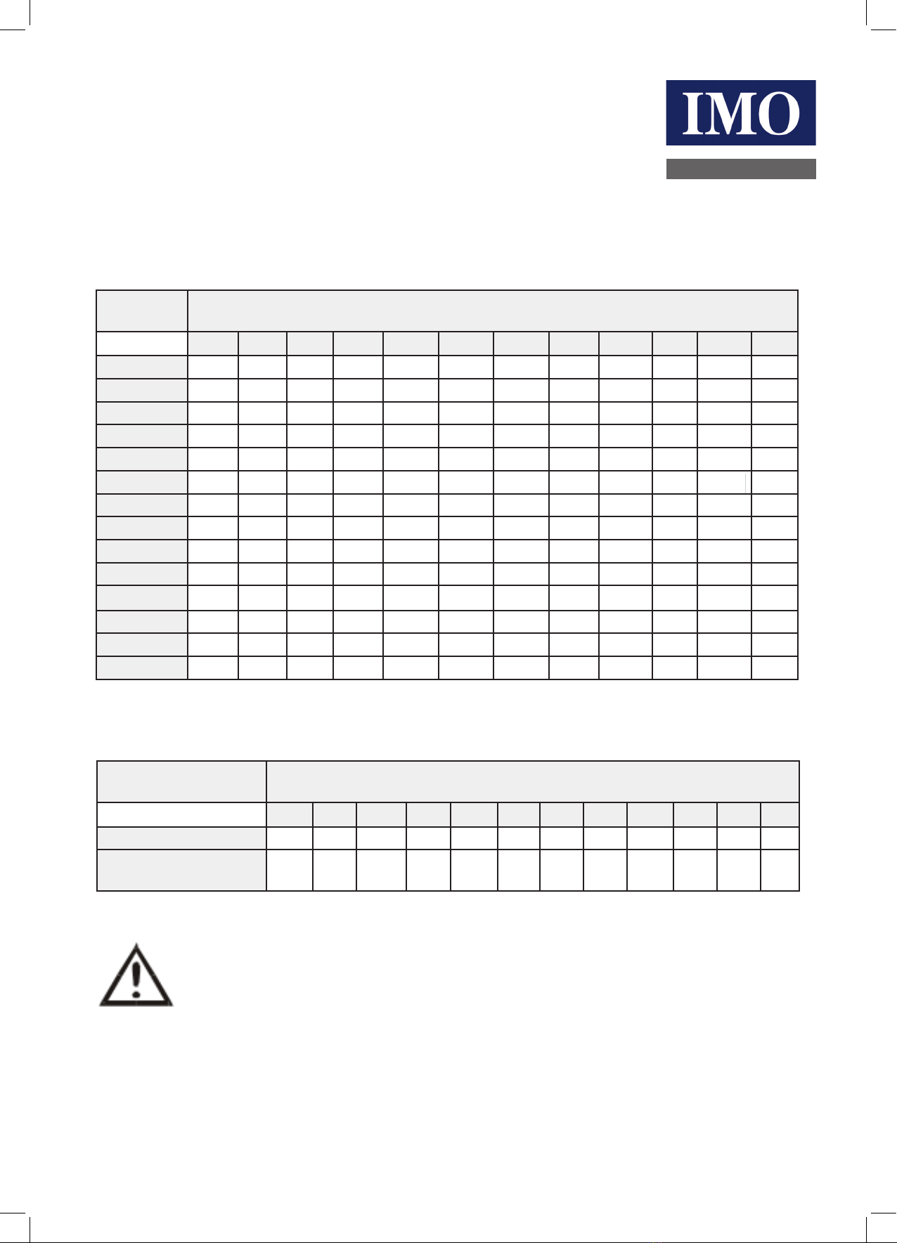
Switch S1 for Thermocouple Input T/C
Type
Temperature Range in °C Switch
K J R S N E B T 1 2 3 4 5 6 7 8 9 10 11 12
0 to 100 400 to 500 0 to 50 0 0 0 0 0 0
0 0 0 0 K
0 to 200 400 to 600 0 to 100 0 0 0 1 0 0 0 0 0 1 J
0 to 400 400 to 800 0 to 200 0 0 1 0 0 0 0 0 1 0 R
0 to 800 400 to 1200 0 to 400 0 0 1 1 0 0 0 0 1 1 S
0 to 125 400 to 525 -50 to 50 0 1 0 0 0 0 0 1 0 0 N
0 to 250 400 to 650 -50 to 100 0 1 0 1 0 0 0 1 0 1 E
0 to 500 400 to 900 -50 to 200 0 1 1 0 0 0 0 1 1 0 B
0 to 1000 400 to 1400 -50 to 400 0 1 1 1 0 0 0 1 1 1 T
0 to 150 400 to 550 -100 to 50 1 0 0 0 0 0 0
0 to 300 400 to 700 -100 to 100 1 0 0 1 0 0 0
0 to 600 400 to 1000 -100 to 200 1 0 1 0 0 0 0
0 to 1200* 400 to 1600 -100 to 400 1 0 1 1 0 0 0
0 to 175 400 to 575 -200 to 50 1 1 0 0 0 0 0
0 to 350 400 to 750 -200 to 100 1 1 0 1 0 0 0
0 to 700 400 to 1100 -200 to 200 1 1 1 0 0 0 0
0 to 1400** 400 t0 1800 -200 to 400 1 1 1 1 0 0 0
*n/a for types N and E
**n/a for types K, J, N and E
Thermocouple Switch S2
All Ranges 1 2 3 4 5 6 7 8 9 10 11 12
0 1 0 0 1 1 1 0 0 0 0 0
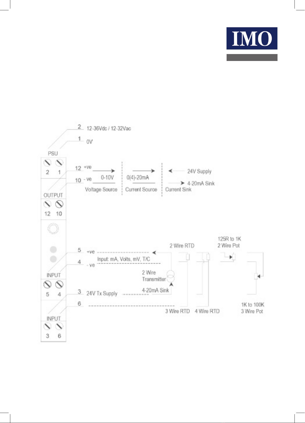
ISOCON-6
24V AC or DC POWERED ISOLATING SIGNAL CONVERTER
Warning: DO NOT OPEN UNIT OR ADJUST SWITCHES WITH POWER SUPPLY, INPUT OR OUTPUT CONNECTED
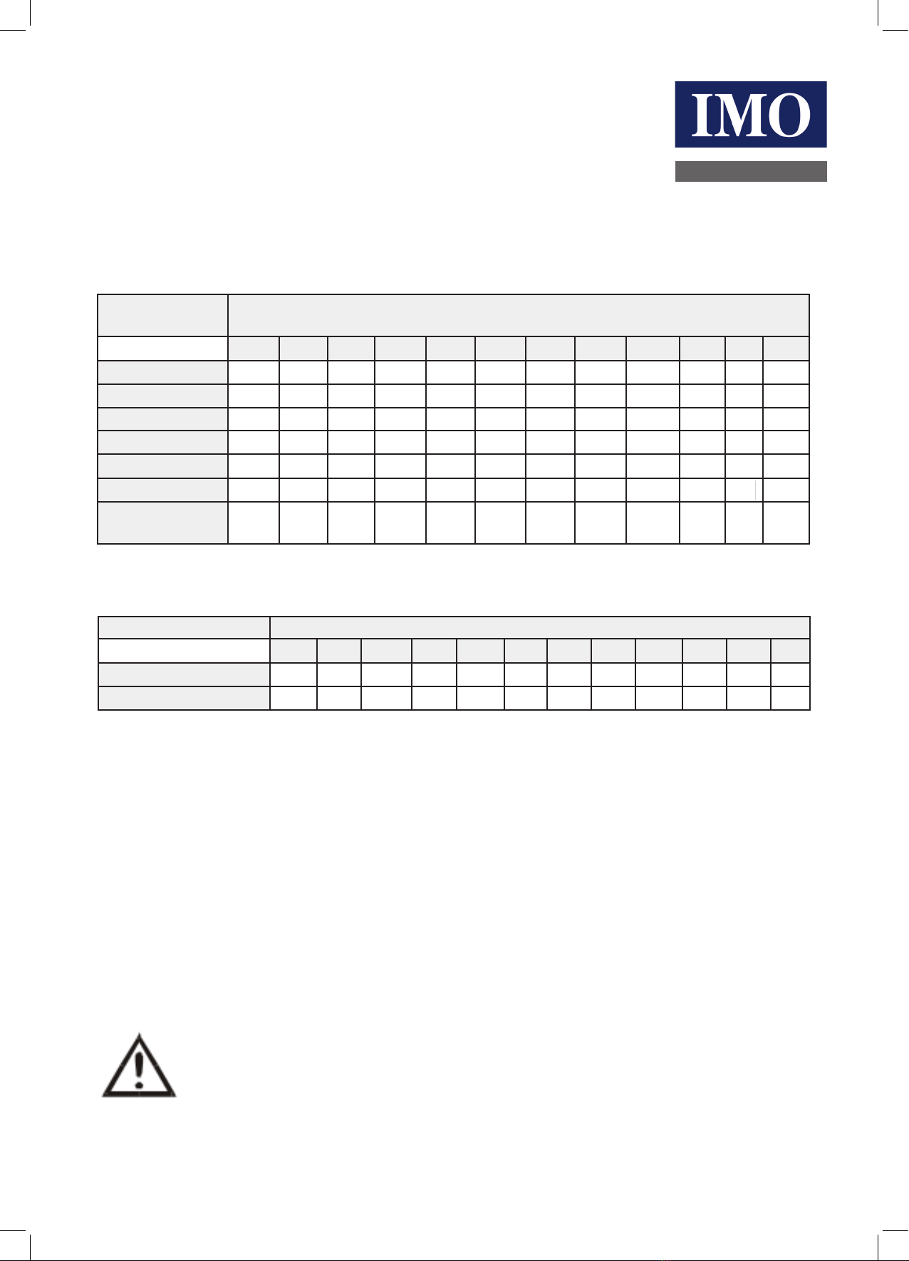
Linearisation ON 0
Linearisation off 1 CJC ON 0
CJC off 1