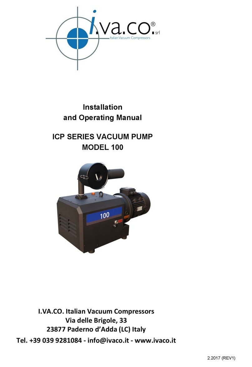
I.VA.CO. ICP Series User manual

I.VA.CO. srl
Installation
And Operating Manual
ICP SERIES VACUUM PUMP
MODELS 255, 305, 415 & 515
www.ivaco.it
2.2017 (REV1)

INSTALLATION&OPERATINGMANUAL
ICP SERIESCLAW
COMPRESSOR
ICP 255,305, 405 & 515
Pleasereadthemanualbeforeoperatingthecompressor.
TABLEOFCONTENTS
4.0 MAINTENANCE
4.1 Compressor Gear Lube Oil (level / type & quantity / change)
4.2 Inline (inlet) Filter
4.3 Maintenance Chart
5.0 PROBLEM SOLVING
6.0 TECHNICAL DATA
7.0 TYPICAL ICP-SERIES ASSEMBLY DRAWING AND PARTS LIST
1.0INSTALLATION
1.1 General description
1.2 Unpacking
1.3 Location
1.4 Power Requirements
1.5 Pressure Connections
1.6 Oil Filling on Gear box
2.0SAFETY
2.1 General Notices
2.2 Warning Label and explanation
2.3 Location of Labels
3.0OPERATION
3.1 Start-up
3.2 Stopping the compressor
3.3 Ambient operating conditions
This manual is written to cover following contact-less operating claw type compressor. The model number
is stamped into the nameplate with serial number: ICP 255, 305, 415 & 515
Please identify the model number and serial number when ordering parts.

INSTALLATION AND OPERATING MANUAL
1.0 INSTALLATION
1.1 General description
The ICP Compressor is dry and contactless machines, enclosed in acoustic sound shied and designed to have
cooling air passed through the sound shied by fan. The warm air is exhausted through the vent. The ICP is
constructed in modular construction consisting of two compartments: pumping and gear chambers separated by
using labyrinth seals. In the pump chamber, as two rotary claws rotate in opposite direction, the air sucked in,
shall be compressed and discharged under pressure. In the gear chamber (box), two gears for synchronizing of
claws rotation will be located with oil lubrication. For reduction of the noise, inlet silencer shall be installed in
compressor inlet side. For a protection of overload, a pressure safety valve or regulating valve is installed in
exhaust. The compressors are directly driven by a flanged motor via a coupling. The ICP Series compressors are
identical in internal construction to ICV vacuum pump, but are outfitted with different inlet and outlet accessories
to allow for operation as a compressor.
1.2Unpacking
Inspect the box and compressor carefully for any signs of damage incurred in transit. Since all compressors are
ordinarily shipped F. O. B. from our factoryor regional warehouse, such damage is the normal
responsibility of the
carrier and should be reported to them.
The compressor is bolted to the skid with studs that are connected through the rubber feet of compressor.
Remove the nuts from the underside do the crate and remove the compressor. Unscrew the studs from the
rubber feet.
The inlet and exhaust of the compressor are covered with plastic caps to prevent dirt and other foreign
substances from entering compressor. Leave these caps in place until you are ready to pipe the compressor to
your equipment.
1.3 Location
Install the compressor in a horizontal position on a level surface so that the pump can be evenly supported on
its rubber feet. Leave 30 ~ 45 cm of access around the compressor to allow proper cooling. Also, adequate
ventilation must be provided for the cooling,
Allow access to the oil sight glass in order to inspect the oil level regularly, and the oil fill and oil drain port for
easy service.
1.4 Power Requirements
A schematic diagram for the electrical motor terminal connections is located in the junction box of the motor or on
the motor nameplate. Typical wirings for Three Phase Motors are as below:
Wiring Scheme- Three Phase Motor
Delta Connection
Low Voltage
L1 L2 L3
W2 U2 V2
U1 V1 W1

The motor must be connected according to the electrical codes through a fused switch in order to protect the
motor against electrical or mechanical overload conditions. The overload of the motor starter must be set at a level
equal to the full load motor current listed on the motor nameplate.
If the compressor is supplied with a motor starter, it is preset at the factory according to customer specifications. It is
advisable to check that these settings are in line with the voltage at your location. If the voltage
is different, please contact I.VA.CO. for motor and starter information.
Correct direction of rotation is marked by an arrow on the motor fan housing and is counterclockwise when looking
at the motor from the motor's fan side.
After electrical connections have been made, the rotation of the motor should be checked. If backward,
reverse any two leads of the three at the power connection.
1. 1.5 Pressure Connections
Use a pipe size that is at least the size of the compressor inlet connections. Smaller lines result in a reduced
compressor capacity.
Compressors operating in parallel on a common main line should have a manual or automatic operated
shut-off valve or positive action check valve, installed in the suction line adjacent to the pump suction
flange. Remove the plastic protective cap from the discharge port prior to connection of compressor to the system.
Should process gas contain dust or other foreign particles, a suitable in line (inlet) filter should be connected to
the inlet port. Consult I.VA.CO:. for recommendations.
Star Connection
High Voltage
L1 L2 L3
W2 U2 V2
U1 V1 W1
The following thread sizes are standard on the compressors (NPT thread is available upon request)
Inlet Size Exhaust Size
G 2"
Model
ICP 255 & 305
ICP 405 & 515 G 3" G 2"
G 3"
@ Inlet Silencer @Exhaust Connection Housing
1.6 Oil Filling on Gear Box
The pump is shipped without oil in gear box. After level installation and correct rotation has been established,
fill the pump with recommended gear oil through the oil fill port. Oil level should be over 3/4 position on the
oil sight glass as shown on the label.

We recommend ISO VG150 gear oil or equivalent oils.
·Shell OMALA HD 150 or Amsoil GEAR LUBE 150 or ANDEROL # 4150
The following table gives the approximate quantities of oil required for each model.
Capacity (liter)
0.90
Pump Model
ICV 255 & 305
ICV 405 & 515 1.80
Do not add fill oil with pump running! Do not overfill.
2.0 SAFETY
Please read the following safety notice carefully before operating the compressor.
2.1 General Notices
-Understand fully this installation and operating manual before operation.
-The other person except authorized operator should not operate the pump
-When the pump is not properly working, it should be stopped immediately.
-I.VA.CO. shall have no liability for any accident and failure arising from no compliance with
instructions in this manual.
-
2.2 Warning labels and its explanation
Following warning labels are shown and attached on ICP series compressors.
2.2.1 Read and Understand a manual:
Read and understand operator’s manual before using this machine
2.2.2 Burn Hazard:
Hot surface. Do not touch.
2.2.3 Loud noise Hazard
Loud noise hazard. Ear protection must be worn.
2.2.4 Hazardous Voltage:
Disconnect power before opening. Contact causes severe electrical shock
.
.
2.3 Location of the labels
The labels of 2.2.1 Read and Understand a manual, 2.2.2 Burn Hazard, and 2.2.3 Loud noise Hazard
shall be shown on the top of sound shield of compressor.
The label of 2.2.4 Hazardous Voltage shall be shown on the cover of motor’s terminal box

3.0 OPERATION
3.1 Start-up
Check rotation of the motor as described in paragraph 1.4 Power Requirements.
Fill the compressor with oil as described in paragraph 1.5 - Oil Filling
Start the compressor with the inlet closed. Run the compressors for a few minutes and then shut down.
Check the oil level again and make sure the oil level is 1/2 position of oil sight glass.
Add oil though oil fill port, if necessary. Pump oil should only be added when the pump is off
3.2 Stopping the compressor
To stop the compressor, turn off the power.
3.3 Operating Conditions and limits
The ICP series are designed to run below set pressures according to the motor power for continuous
operation. Operation over maximum pressure level may result in failure of and severe damage to the
machine. Pressure Regulator installed in outlet flange is set at maximum allowable pressure (see the table
for set of pressure) at factory.
Caution: Any non compliance may lead to severe injury to persons and damage to the compressor.
The pressure can be adjusted by turning the stud of pressure regulating valve on the top of valve. The
regulating valve or safety valve is set at permissible operating pressure and will be opened to discharge the
pressure if the compressor runs over the setting pressure for a safety operation.
Caution: Do not run the compressor without regulating valve or safety valve. Do not set the regulating
valve or safety valve at over permissible pressure. The compressor may be damaged severely.
The standard version is for use of dry air only, and may not be used in hazardous areas. Handling of humid
air or gases containing aggressive chemicals is possible only with specially configures units. Consult
I.VA.CO. for assistance.
Also it is recommended for operating personnel who is working near the compressor to wear ear protectors. If
noise below the designed dBA is required, an external sound enclosure can be added to the system,
provided adequate ventilation is provided
The ambient and suction air temperature must be between 5 and 40 °C deg
Caution: Any non compliance may lead to severe injury to persons and damage to the compressor
4.0 MAINTENANCE
ICP Series Compressors require very little maintenance. To ensure optimum performance, the
following maintenance steps should be followed:
4.1 Compressor Lube Oil
4.1.1 Gear Oil Level
Check the oil level on monthly basis. Under normal circumstances it should not be necessary to add oil between
oil changes. A significant drop in oil level means there is an oil leak. Please check the o-rings, drain plug or oil
sight glass.
Check the oil level only when the compressor is shut off. Replenish oil if it drops below bottom position of the
sight glass.
Caution: Do not add oil while the compressor is running, since hot oil can escape from the oil fill port.

4.1.2 Gear Oil Type and Quantity
See section 1.5 - Oil Filling - for details on oil type and quantity
4.1.3 Oil Change
Under normal ambient conditions with proper Gear Oil, it is recommended to change the oil every 10,000
operating hours. It is necessary to make the first oil change between 500 ~1000 operating hours..
Caution: If different brand oil is being filled, the old oil must be drained completely from the gear box.
Caution: Above interval of lubrication is based on ambient temperature of 20
°
C. At 40
°
C ambient
temperature operation, it may be shorten to half.
4.2 Inline (Inlet) Filter
Check inline (inlet) filter on a weekly basis. The filter cartridge should be cleaned or replaced when
dirty. Consult service agent for replacement element information.
Caution: Depending on the mounting position of the filter, be careful not to allow accumulated
foreign material to fall in the pump suction inlet when removing the filter cartridge. Horizontal filter
installation is recommended to prevent this.
4.3 Maintenance Chart
Weekly: Check inline inlet filter element. More often if high particulates in inlet stream
Monthly: Check the oil level, Protective Mesh.
Semi-Annually: Check cooling fan and coupling
Annually: Check Bearings/ Shaft Seals, More frequently if operated at ambient temperature
exceeding 20°C
Every 5000 operating hours: Check the gear oil conditions, and if necessary, change the oils.
Inspection hole with G1" plug: Check the coupling and its insert, and fan through this hole regularly. (The
endoscope(WireCam) can be used with Smart Phone software)

5.0 PROBLEM SOLVING
5.1 Problem
Compressor does not reach capacity.
5.1.1 Possible Cause
Inlet screen (mesh) of the inlet filter clogged with debris.
Remedy : check inlet filter element and clean screen (mesh) by compressed air or wash it.
5.1.2Possible Cause
Pipe work is too long or small.
Remedy : Use the bigger diameter pipe and shorten the lines length if possible.
5.2 Problem
Compressor runs over set pressure.
5.2.1 Possible Cause
Pressure Regulator or Safety Valve set over the set point, or is out of order.
Remedy : Set the point again or replace it with new one.
5.3 Problem
Compressor does not reach the set pressure.
5.3.1 Possible Cause
Leak on the compressor or system.
Remedy : Check the leak on the compressor or system.
5.4 Problem
Compressor runs very noisy.
5.4.1 Possible cause
Contamination of the claws.
Remedy : Clean the pumping chamber and rotary claws.
5.4.2 Possible cause
Coupling insert is worn.
Remedy : replace coupling insert in motor/pump coupling.
5.4.3 Possible Cause
Bearing noise
Remedy : replace bearings or call service agent for service or exchange program.
5.5 Problem
Compressor will not start.
5.5.1 Possible Cause
Supply voltage is not proper or is overloaded. Motor starter overload settings are too low or improper;
fuses are burned; wire size is to small or too long causing a voltage drop.
Remedy : check voltage supply; overload settings in motor starter for size and settings
according to motor nameplate. Install proper size wire. If ambient temperature is high,
use the next larger size overloads or adjust settings 5% above motor nameplate value.
Remedy : turn compressor fan by hand. If it will not turn, remove motor from Compressor and check
motor and compressor separately. Repair or replace if needed or call service agent for service or
exchange program.

5.6 Problem
Compressor is running too hot.
5.6.1 Possible Cause
Not enough air ventilation to Compressor
Remedy : Make certain a sufficient amount of fresh air is supplied to the Compressor.
Dirty or Blocked Mesh
Remedy : Check the flow of cooling air and clean the metal mesh of any debris blocking the air as
necessary.
5.6 Problem
Compressor will not operate (seized up).
5.7.1 Possible cause
Rotary Claws, Bearings or Gears stuck on..
Remedy : Call service agent for service or exchange program
6.0 TECHNICAL DATA
Model 60Hz
50Hz
60Hz 0.8 1.4 1.8 2.2 ~ 1.2 2.2 0.6 1.2 1.6 2 0.8 - 1.6 2
50Hz 1 ~ 2 ~ 0.6 1.4 2.2 0.8 1.4 1.8 2 0.8 1.2 1.6 2
60Hz 9 11 13 15 ~13 18 13 18 22 26 18 -26 36
50Hz 7.5 ~ 11 ~ 7.5 11 15 11 15 18.5 22 15 18.5 22 30
RPM - 60/50Hz RPM
Voltage, Available V
60Hz
50Hz
Oil Capa (Gear box) Ltr
Inlet / Outlet Conn. **BSP(G)
W x H (mm) 60Hz 1001 1171 1171 1171 ~1183 1183 1274 1274 1340 1395 1289 ~1410 1410
50Hz 961 ~1171 ~973 1183 1183 1274 1274 1274 1340 1289 1289 1355 1410
Amb. Operating Temp (ºC)
Accessories
400 500
ICP 255 ICP 305 ICP 405 ICP 515
300 360 480 600
Press. Conti., Bar
Kw
M3/ Hour
208~230/460V, 220~240 / 380~420V, 400/690V
dB(A), Ave 82 82 83 83
79 80 81 82
3450 / 2850
250 300
L* (mm)
5ºC ~40ºC
Pressure Regulator, Safety Valve, Inlet Silencer, and Inlet Filter
Note: 1) * Length varies to motor mfg 2) **NPT threads available upon request
0.9 1.8
2" 3"
573 x 757 573 x 757 672 x 1003 672 x 1003
Note: Ultimate Continuous pressure operation will be possible within ambient operating
temperature between 5~40ºC.

ICP-255
"A" "B"
50Hz, 7.5Kw :961mm -
60Hz, 9.2Kw :1,001mm -
50Hz, 11Kw :1,171mm 379mm
60Hz, 15Kw :1,171mm 379mm
60Hz, 15Hp :1,139mm 389mm
60Hz, 20Hp :1,183mm 433mm
60Hz, 25Hp :1,239mm 468mm
166
494
646
757
398
573
501
474
96
611
731
34
"B"
"A"

ICP - 305
"A" "B"
50Hz, 7.5Kw :973mm -
50Hz, 11Kw :973mm 379mm
50Hz, 15Kw :973mm 379mm
60Hz, 15Kw :973mm 379mm
60Hz, 18.5Kw :973mm 379mm
60Hz, 20Hp :1,195mm 433mm
60Hz, 25Hp :1,251mm 468mm
34
"B"
"A"
625 745
646
757
398
573
474
474
96
414
180
494

ASS'y DRAWING
ICP-255 / 305 (IEC)

ASS'y DRAWING
ICP-255 / 305 (NEMA)

POS# Description Q'ty POS# Description Q'ty POS# Description Q'ty
1 Gear Box Housing 160 Inlet flange, Upper Housing, G 2" 1153 Elbow, inlet 2" 1
2 Gear Box Cover (rear) 161 Inlet screen (Conical ) 1155 Plug 1-1/2" 1
4 Pump Housing Cover 1 (End Plate) 162 O-Ring, Inlet Flange, upper part 1158 Base 1
6 Fan Housing 175 Bracket with Elbow 1159 Cover, Exhaust 1
10 Sleeve 276 Plate (vertical) 1160 Seal 1
11 Shaft 1 177 Accoustic mat 1161 Elbow, Exhaust 2" 1
12 Shaft 2 178 Plate (horizontal) 1162 Bushing 2" x 1-1/2" 1
13 Gear 1 279 Support isolator 12 163 Pipe, extension, Exhaust 1
15 Rotor 1
181 Gasket, Oil Sight Glass 1269 Bolt / M12 x 40 2
16 Rotor 2
183 Oil Sight Glass 1270 Hexagon Nut / M12 2
17 Spacer
285 Pipe, for Drain Pulg 1271 Washer, Spring Lock / M12 2
18 Piston Ring
486 O-ring, Drain Plug 2272 Foot, Rubber for Motor M10 1
19 Sleeve
287 Drain Plug 1571 Washer, Spring Lock, 6mm 8
20 O-Ring
288 Oil filler Breather, Plastic 1573 Washer, Spring Lock, 10mm 11
21 Shaft Seal,
289 O-Ring for Oil filler 1574 Washer, Spring Lock, 12mm 22
22 Bearing,
292 Shield Cover, Bottom 1577 Hexagon Nut M10 11
23 Bearing cover (Plate)
193 Accoustic Mat for Shield Cover, Bottom 1641 Hex. Socket Head Cap Screw / M5 x 15 5
24 Bearing cover
194 Shield Cover, Side 1643 Hex. Socket Head Cap Screw / M6 x 10 4
25 Key, for Gear
295 Shield Cover, Front 1644 Hex. Socket Head Cap Screw / M6 x 15 12
26 Key, for Coupling
196 Accoustic Mat for Shield Cover, front and Side 1650 Hex. Socket Head Cap Screw / M6 x 65 4
27 Sleeve
297 Foot, Rubber 7656 Hex. Socket Head Cap Screw / M12 x 25 2
28
Power Lock (ICP 305)
2(4) 100 Coupling, Pump Side 1670 Hex. Socket Head Cap Screw / M12 x 50 14
30 Flinger
2101 Insert, Coupling 1673 Hex. Socket Head Cap Screw / M12 x 110 4
31 Sleeve
2102 Coupling, Motor Side 1678 Hex. Socket Head Cap Screw / M12 x 25 2
32 Bearing,
2103 Fan, new, Plastic 1695 Hexagon Bolt / M12 x 25 4
33 Locking Disk
1105 Flange Adapter 1696 Hexagon Bolt (NEMA only) 4
34 O-Ring
1110 Motor 1697 Hexagon Bolt / M12 x 35 4
35 Sleeve
1115 Base W/Bolt, Nut for Motor 1707 Set Screw / M8 x 15 2
36 Shaft Seal,
1121 Silencer, Inlet 1709 Set Screw / M8 x 10 2
37 O-Ring, Compressor cover,
1126 Safety Valve 1710 Set Screw / M10 x 15 3
38 O-Ring, Gear Box cover,
1130 Label, Direction Arrow 1711 Set Screw / M10 x 20 4
39 Dowel Pin
4131 Name Plate 1712 Set Screw / M10 x 25 3
40 Locking Disk
1150 Inlet Filter IF-230 1713 Set Screw / M10 x 35 4
47 Locking Disk, side Rotor
2151 Pipe, extension, Short, inlet 2" 2716 Eye Bolt M12 1
52 Gasket, Exhaust Silencer, Steel Silencer
1152 Pipe, extension, inlet 2" 1724 Botton Flange Bolt M5x8 44
ICP 255 / 305 PART LIST

ICP - 405 Dimensions
"A" "B"
50Hz, 11Kw :1,274mm -
50Hz, 15Kw :1,274mm -
60Hz, 15Kw :1,274mm -
50Hz, 18.5Kw :1,274mm -
60Hz, 18.5Kw :1,274mm -
50Hz, 22Kw :1,340mm 346mm
60Hz, 22Kw :1,340mm 346mm
60Hz, 30Kw :1,395mm 514mm
60Hz, 20Hp :1,286mm
60Hz, 25Hp :1,287mm 438mm
60Hz, 30Hp :1,381mm 510mm
60Hz, 40Hp :1,391mm 494mm
-

ICP - 515 Dimensions
"A" "B"
50Hz, 15Kw :1,289mm -
50Hz, 18.5Kw :1,289mm -
60Hz, 18.5Kw :1,289mm -
50Hz, 22Kw :1,355mm 346mm
50Hz, 30Kw :1,410mm 514mm
60Hz, 30Kw :1,410mm 514mm
60Hz, 37Kw :1,410mm 514mm
60Hz, 25Hp :1,302mm -
60Hz, 40Hp :1,406mm 494mm
60Hz, 50Hp :1,444mm 532mm

ASS'y DRAWING
ICP-405 / 515 (IEC)

ASS'y DRAWING
ICP-405 / 515 (NEMA)

POS# Description Q'ty POS# Description Q'ty POS# Description Q'ty
1 Gear Box Housing 160 Inlet Flang 1153 Elbow, inlet 2" 1
2 Gear Box Cover (rear) 161 Inlet screen (Conical ) 1155 plug 1-1/2" 1
4 Pump Housing Cover (End Plate) 162 Gasket, Inlet Flange 1158 Base 1
6 Fan Housing
175 Bracket with Elbow 1159 Cover, Exhaust 1
10 Sleeve
276 Plate (vertical) 1160 Seal 1
11 Shaft 1
177 Accoustic mat 1161 Elbow, Exhaust 2" 1
12 Shaft 2
178 Plate (horizontal) 1162 Bushing 3" x 1-1/2" 1
13 Gear
279 Support isolator 15 163 Pipe, extension, Exhaust 1
15 Rotor 1
181 Gasket, Oil Sight Glass 1269 Bolt / M14 2
16 Rotor 2
183 Oil Sight Glass 1270 Hexagon Nut / M14 2
17 Spacer
285 Pipe, for Drain Pulg 1271 Washer, Spring Lock / M14 2
18 Piston Ring
486 O-ring, Drain Plug 2272 Foot, Rubber for Motor M12 1
19 Sleeve
287 Drain Plug 1571 Washer, Spring Lock, 6mm 16
20 O-Ring
288 Oil filler Breather, Plastic 1573 Washer, Spring Lock, 12mm 17
21 Shaft Seal
289 O-Ring for Oil filler 1574 Washer, Spring Lock, 10mm 14
22 Bearing,
292 Shield Cover, Bottom 1577 Hexagon Nut M12 13
23 Bearing cover
293 Accoustic Mat for Shield Cover, Bottom 1641 Hex. Socket Head Cap Screw / M5 5
25 Key, for Gear
294 Shield Cover, Side 1643 Hex. Socket Head Cap Screw / M5 4
26 Key, for Coupling
195 Shield Cover, Front 1644 Hex. Socket Head Cap Screw / M6 16
27 Sleeve
296 Accoustic Mat for Shield Cover, front and Side 1651 Hex. Socket Head Cap Screw / M16 4
28
Power Lock (ICP-515)
2(4) 97 Foot, Rubber 9653 Washer, Spring Lock, 16mm 4
30 Flinger
2100 Coupling, Pump Side 1656 Hex. Socket Head Cap Screw / M12 2
31 Sleeve,
2101 Insert, Coupling 1670 Hex. Socket Head Cap Screw / M10 14
32 Bearing
2102 Coupling, Motor Side 1673 Hex. Socket Head Cap Screw / M10 4
33 Locking Disk
1103 Fan, new, Plastic 1678 Hex. Socket Head Cap Screw / M16 2
34 O-Ring
1105 Flange Adapter 1695 Hexagon Bolt / M12 4
35 Sleeve,
1110 Motor 1696 Hexagon Bolt (NEMA only) 4
36 Shaft Seal
1115 Base W/Bolt, Nut for Motor 1697 Hexagon Bolt / M12 4
37 O-Ring, Compressor cover,
1121 Silencer, Inlet 1707 Set Screw / M8 2
38 O-Ring, Gear Box cover,
1126 Safety Valve 1709 Set Screw / M8 2
39 Dowel Pin
4130 Label, Direction Arrow 1710 Set Screw / M12 5
40 Locking Disk
1131 Name Plate 1711 Set Screw / M12 4
47 Locking Disk, Front
2150 Inlet Filter IF-230 1712 Set Screw / M12 5
52 Gasket, Exhaust
1151 Pipe, extension, Short, inlet 2" 2716 Eye Bolt M16 2
57 Stud Bolt
4152 Pipe, extension, inlet 2" 1724 Botton Flange Bolt M5 33
ICP 405 / 515 PART LIST

I.VA.CO.
Italian Vacuum Compressors
Via delle Brigole, 33
23877 Paderno d’Adda (LC)
Italy
+39 039 9281084
www.ivaco.it
Other manuals for ICP Series
1
This manual suits for next models
4
Table of contents
Other I.VA.CO. Water Pump manuals
Popular Water Pump manuals by other brands

Watson Marlow Pumps
Watson Marlow Pumps 504Du manual

BLACKMER
BLACKMER V Series Installation, operation and maintenance instructions

UPRENT
UPRENT impulse MUMBAI IP Series user manual

Verderflex
Verderflex Dura 7 operating manual

Dustcontrol
Dustcontrol TPD 30 Original instructions

Marina
Marina 75 instruction manual

Aurora
Aurora 330 Instruction and repair manual

LEYBOLD
LEYBOLD Sogevac NEO D 16 Original instruction manual

HEISSNER
HEISSNER HFP7000-00 Instructions for use

Lutz-Jesco
Lutz-Jesco MEMDOS SMART LK operating instructions

Pfeiffer Vacuum
Pfeiffer Vacuum UNO 35 operating instructions

Samoa
Samoa 560 230 Technical service guide