i-Vac SB24016-EU-A User manual

For safe operation and to gain the full benefit of your iVAC Switch Box -
please read through this handbook before use.
Retain this handbook and your proof of purchase for future reference.
16A 15391-1100 ENGLISH-R8 08/19 PAGE 1 of 8
MODEL
SB24016-EU-A

This iVAC Swi ch Box enables he au oma ic and remo e swi ching
of a dus collec ing vacuum.
This iVAC Swi ch Box is in ended o be used wi h a power ool
such as a rou er, planer, saw, grinder or sander and an associa ed
vacuum.
The in elligen power sensing, elec ronic ON and OFF delays
op imise your dus collec ion and reduce power consump ion.
16A 15391-1100 ENGLISH-R8 08/19 PAGE 2 of 8
Access panel to
IP switches on
rear of box.
PH1 screwdriver
required.

DESCRIPTION AND FEATURES
The two, 16A socket outlets on the Switch Box are specific and labelled TOOL &
VACUUM.
The vacuum turn ON delay of 1 or 2 seconds (configurable – see settings on page
4) is to prevent the start up power surges of the power tool and vacuum coinciding
and overloading your Switch Box and/or power source circuit breakers.
The vacuum turn OFF time of 8 or 16 seconds (configurable – see settings on
page 4) is to clear dust and debris from your power tool, workstation and hose.
The resettable 16A circuit breaker is provided for overload and fault protection.
The 4 mounting tabs enable secure fastening to walls, benches and equipment.
The integral earth terminal is provided for bonding (grounding) accessories, for
static grounding.
The Switch Box is designed to control LVHP vacuums up to 2700 watts and HVLP
extractors up to 1.5 hp. Further details on page 6.
The maximum o al load (power tool and the vacuum) is 3500 watts ≈ 16A.
OPERATION
A vacuum plugged in to the
Switch Box is controlled
by 3 user selectable modes:
► AUTO ◄
As the power tool is used the vacuum will au oma ically switch ON and OFF
► O ◄
The vacuum is permanently OFF regardless of the state of the power tool.
► I ◄
The vacuum is permanently ON regardless of the state of the power tool.
16A 15391-1100 ENGLISH-R8 08/19 PAGE 3 of 8
3 position
MO E
switch

SETTINGS (CONFIGURATION)
For most applications, the factory (default) settings do not need changing.
If required, the Switch Box can
be configured to suit a user's
specific equipment and
application. There are IP
switches that can be set by the
user.
Se he Power Tool AUTO swi ching hreshold o S andard, Medium or High
Some power tools draw power even when the motor is not running -
e.g. work lights, standby electronics, speed controllers or ancillary devices.
N.B. - Some experimentation may be required to determine the correct setting.
STANDARD
≈ 150 mA ≈ 35W
MEDIUM
≈ 250 mA ≈ 60W
HIGH
≈ 500 mA ≈ 120W
2 - OFF, 3 - ON, 4 – OFF
(factory settings)
2 - OFF, 3 - OFF, 4 – ON 2 - ON, 3 - OFF, 4 - OFF
Se he Vacuum urn ON delay and OFF ime
VACUUM OFF TIME
Useful for long hose lengths
and clean up after working
VACUUM ON DELAY
Useful for extractors with a
high start up power demand
5 - OFF ≈ 16 secs
5 - ON ≈ 8 secs
(factory setting is ON)
6 - OFF ≈ 2 secs
6 - ON ≈ 1 secs
(factory setting is ON)
16A 15391-1100 ENGLISH-R8 08/19 PAGE 4 of 8
IP switches.
Factory settings shown.
3, 5 and 6 are ON
1, 2 and 4 are OFF
IP switch 1 is
reserved for future
applications – Leave
OFF
When accessing the
IP switches through
the rear panel – the
Switch Box must be
safely disconnected
(isolated) from the
mains supply.

SAFETY
Misuse of your Switch Box and any equipment
plugged into it can potentially lead to injury and damage.
o not exceed the maximum o al load of 16A (≈ 3500watts)
This is the load of the vacuum and power tool combined.
Overload and fault protection is provided by the 16A circuit
breaker, Frequent overloading indicates a problem that
requires investigation – see page 7.
Ensure the power tool and vacuum are plugged into the
correct socket outlet on the Switch Box.
o not connect any hazardous tools or equipment to the
Vacuum outlet on the Switch Box.
o not alter, modify or adapt the Switch Box.
o not open the Switch Box housing.
The Switch Box is suitable for indoor use, in dry environments
only.
The Switch Box mus only be connected to an adequately rated
and earthed power source (e.g. A 16A socket outlet) that is RC
protected.
When accessing the IP switches through the rear access panel
– the Switch Box must be safely disconnected from the mains
supply.
Never use the Switch Box with the rear access panel removed.
Use extension leads and power adaptors with extreme caution – they must be
suitably rated, specified, earthed and uncoiled.
Inspect your Switch Box regularly - o not use if the housing, controls, leads or
connectors are damaged or worn.
We strongly recommend appropriate portable appliance testing (PAT) of the
Switch Box, your power tools, vacuums, adaptors and extension leads.
Unplug (isolate) the Switch Box when unattended. e.g. night time and weekends.
16A 15391-1100 ENGLISH-R8 08/19 PAGE 5 of 8
Apply the supplied
AUTION label to
your vacuum to warn
that it can be started,
remotely, by another
person.
Apply the
supplied 16A
label to your 16A
Schuko plug

TECHNICAL DATA - SB24016-EU-A
220 - 240V 50/60 Hz AC. Maximum o al load is 16A ≈ 3500watts.
Maximum vacuum (LVHP) power is 12A ≈ 2700watts.
Maximum ex rac or (HVLP) power is 1.5 hp.
Vacuum turn ON delay is configurable – 1 or 2 seconds (factory set to 1).
Vacuum turn OFF time is configurable – 8 or 16 seconds (factory set to 8).
Power tool AUTO switching threshold is configurable – Standard, Medium or High
(factory set to Standard ≈ 35 watts ≈ 0.15A).
Circuit breaker is 16A type 'B', user resettable.
Suitable for continuous operation.
Housing – ABS 94V0 fire retardant.
Housing – 128mm wide. 177mm high (incl fixing tabs). 56mm deep. 580 grams.
Supply lead is ≈ 3 feet, fitted with a type F (Schuko) plug. 16A max rating.
Approvals – CE, RoHS.
Protection – IP20, indoor use, dry environments only - Class I, requires earth.
The Switch Box is NOT suitable
for controlling vacuums / extractors
which are NVR (No Volt Release)
protected – see page 7.
NOTE: OL motor starters include
NVR protection.
HVLP extractors over 1.5 hp could cause an overload
to the Switch Box due to their high start-up power demand.
16A 15391-1100 ENGLISH-R8 08/19 PAGE 6 of 8
Typical NVR
Switch
Typical HVLP
(high volume – low pressure)
Extractor
(with NVR)
MAX 1.5 hp
Typical LVHP
(low volume – high pressure)
Vacuum
(without NVR)
MAX 2700 watts
Typical DOL
Motor Starter
with NVR

TROUBLE SHOOTING
NEITHER YOUR VACUUM OR POWER TOOL ARE OPERATING
Cause 1 > The 16A circuit breaker has tripped out - Your Switch has been subjected to a power
overload (i.e. more than 16A ≈ 3500 watts) or there is a fault (i.e. a short circuit in your
vacuum or power tool)
Remedy 1A > Reset the circuit breaker on your Switch Box - press it in to reset.
Remedy 1B > Check there is power present at your socket outlet - reset the power supply
circuit MCBs and RC s as required
Cause 2 > Your extractor may draw a very high current during start up - your Switch may
have been subjected to a power overload caused during start-up
Remedy 2 > Try increasing the vacuum turn ON delay to 2 seconds (see settings on page 4)
YOUR VACUUM DOES NOT OPERATE IN AUTO MODE BUT IT DOES OPERATE IN
MANUAL (I) MODE
Cause > The Switch Box AUTO function is only suitable for power tools that draw 35 watts
or more when running. You can confirm this by plugging another (more powerful)
power tool into the Switch Box and operating it
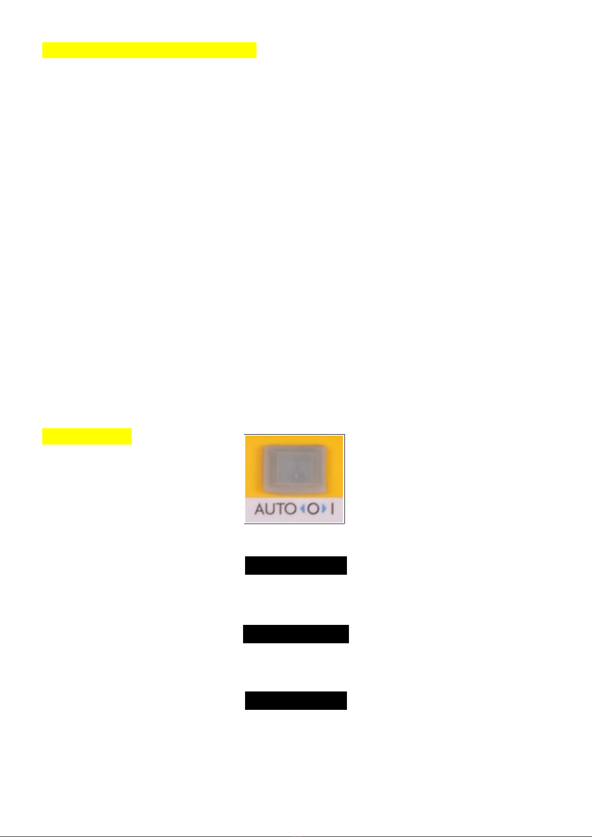
Remedy A > Control your vacuum in the manual mode – ON or OFF (I or O)
Remedy B > Adjust the AUTO switching threshold to a lower setting (see settings on page 4)
YOUR VACUUM OPERATES CONTINUOUSLY IN AUTO MODE WHETHER YOUR POWER
TOOL IS ON OR OFF
Cause > The Switch Box is configured at the factory for power tools that draw less than 35
watts when on standby. Some power tools draw more than 35 watts even when
not running – this is typically power used by work lights, standby electronics,
speed controllers or ancillary devices. You can confirm this by plugging another
power tool into the Switch Box and operating it
Remedy A > You can increase the power tool AUTO switching threshold by configuring the IP
switches (see settings on page 4)
Remedy B > Control your vacuum in the manual mode – ON or OFF (I or O)
YOUR EXTRACTOR SWITCHES ITSELF OFF – THE NVR ON YOUR EXTRACTOR
DISCONNECTS THE MOTOR
Cause > Some vacuums and most extractors are fitted with an NVR (No Volt Release)
switch (also known as Magnetic Switch or OL - see page 6). NVR switches will
automatically disconnect when the supply power is switched off, this is normal
operation. This Switch Box is no suitable for NVR protected vacuums
Remedy > iVAC offers other products in it's range (e.g. the iVAC Pro System) that are suitable
for NVR protected vacuums and extractors.
16A 15391-1100 ENGLISH-R8 08/19 PAGE 7 of 8

GUARANTEE - SB24016-EU-A
The iVAC Switch Box is guaranteed against defects in material and workmanship,
under normal usage, for one year from the date of purchase.
This guarantee is not transferable and does not affect your statutory rights.
This guarantee does no apply in cases of improper use, negligence, lack of
maintenance or accidental damage.
Under the terms of this guarantee a faulty Switch Box will either be repaired or
replaced free of charge.
Liability is limited to the Switch Box only, no other costs will be reimbursed.
This guarantee does not confer any rights other than those expressly set out
above.
SERVICE AND REPAIRS
The iVAC Switch Box can be repaired and maintained in our UK workshop.
Beyond the guarantee period (one year) these repairs are chargeable.
We can provide a quote once the Switch Box has been inspected and tested.
Repair charges will always be lower than a replacement (new) Switch Box.
CONTACT
Uni ed Kingdom - Toolova ion
www.toolovation.co.uk
01531 636819
Canada (head office) - iVAC
www.ivacswitch.com
16A 15391-1100 ENGLISH-R8 08/19 PAGE 8 of 8
Table of contents
Other i-Vac Switch manuals
Popular Switch manuals by other brands

ANTAIRA
ANTAIRA LNX-1002C-SFP Series Quick installation guide

Plantronics
Plantronics BIWAY HEADSET manual

Hirschmann
Hirschmann RS20 series user manual

Edimax
Edimax Rackmount Fast Ethernet Switch Quick installation guide

ABB
ABB Zenith ZTG T Series Operation, maintenance, and installation guide

D-Link
D-Link EasySmart DGS-1100-05 user manual

CYP
CYP PUV-2608TX Operation manual

HP
HP ProCurve 2510-24 Installation and getting started guide

FS
FS S5800-48F4SR-DC quick start guide

Becos
Becos TS8-MS Overdrive Midi Switching user manual

Agilent Technologies
Agilent Technologies 86060C Series Product overview

Extreme Networks
Extreme Networks Px Series Installation and configuration guide