manuals.online logo
Brands
  1. Home
  2. •
  3. Brands
  4. •
  5. IBC
  6. •
  7. Boiler
  8. •
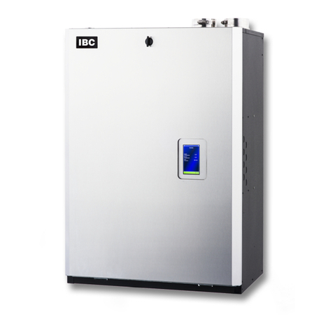
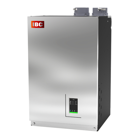
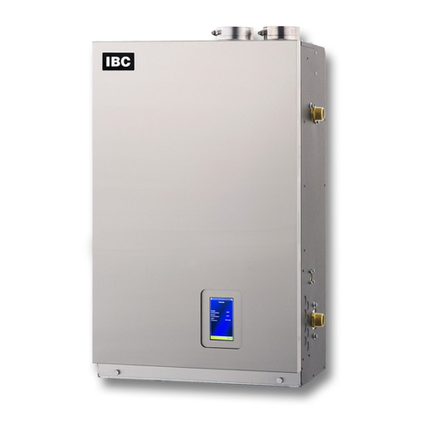
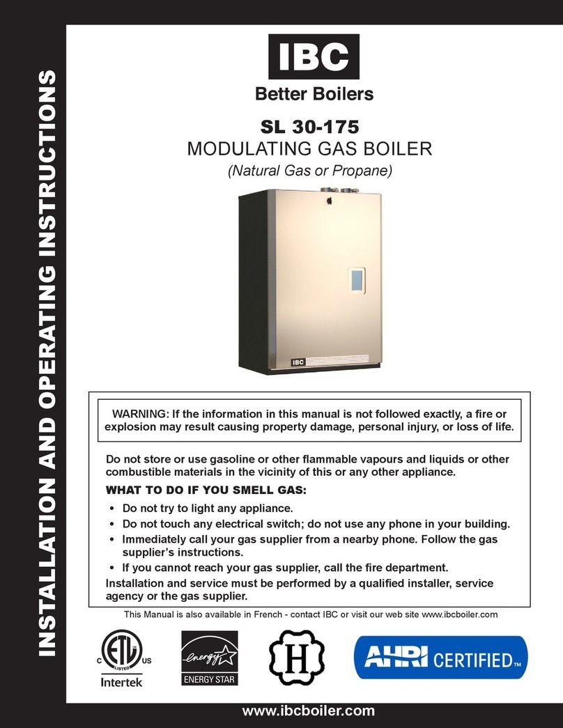
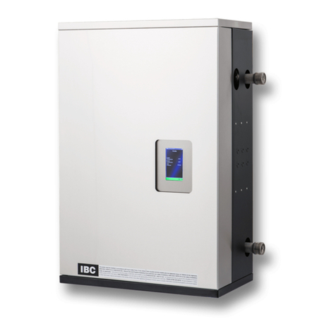
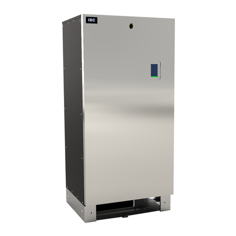
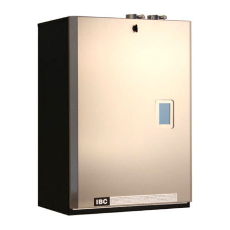
  9. IBC VX 110 User manual

IBC VX 110 User manual

Quick Reference Installation Guide
For gas delivery to the boiler, we recommend using hard
piping rather than exible piping. If you use exible piping,
ensure that the gas pipe size is appropriate for the maximum
BTU input of the boiler.
Minimum Gas Pressure 4" w.c.
Maximum Gas Pressure 14" w.c.
Size piping for sufcient sustained gas delivery at sufcient
pressure to the boiler.
Recommended Supply Pressure at Full Load
Natural Gas 7"
Propane 10"
• Ensure that there is a minimum of 6 feet of piping
between the boiler and gas regulators.
• Use a manometer to test that gas delivered to the boiler
is delivered at sufcient pressure and that “lock up” does
not exceed the maximum pressure.
• If using a 5 psi to inches vented gas regulator, always
oversize the vent pipe to prevent hunting of the gas
regulator when boilers are ring at lower output levels.
• We strongly recommend against using copper gas lines.
In retrots with existing copper gas pipes, we highly
recommend replacing the pipes with black iron or
stainless steel piping sized correctly for the boiler. If the
copper gas pipes must remain, clean and clear the gas
piping of any debris before connecting to the boiler.
Failure to do so can result in a blocked gas valve. and
inconsistent performance.
Maximum Pipe
Length by Model ½" IPS ¾" IPS 1" IPS 1¼"IPS
VX 110 (Natural Gas) 30' 125' 400' 1,600’
VX 110 (Propane) 90' 350' 1,000' 2,000’
VX 150 (Natural Gas) 20’ 80’ 200' 900’
VX 150 (Propane) 50' 200' 600'2,000’
VX 199 (Natural Gas) 10' 40' 150' 900'
VX 199 (Propane) 30' 125' 400' 1,400'
1. Place the vacuum breaker cap over the vacuum
breaker opening and push rmly
2. Fill the condensate trap with water.
3. Attach the trap to the drain hose, and tighten the
drain compression (including washer)
4. Slide the trap over the boiler drain outlet, and tighten
upper union nut. Secure the upper union nut with the
outlet clip.
5. Check for leaks.
Gas Supply (Section 3.12)
Boiler Mounting (Section 3.4 of the manual)
Venting (Sections 3.5 and 3.7)
Follow the venting specications for the correct materials and
venting lengths provided in the above sections of the manual.
• Ensure that sidewall congurations have adequate vertical
separation, and that exhaust plumes are well away from all
building air intake vents.
• Ensure that all venting material is sloped towards the boiler.
PP venting must be sloped at a minimum of ⅝″ per foot to
ensure that no leaks occur via gaskets.
• Ensure that PPs venting is supported every 36″ (min).
• On longer horizontal runs of PVC and CPVC, increase the
grade to ⅜″ or more.
• Fully insert approved venting material into the boiler’s
exhaust outlet. Then, tighten the clamp to lock the venting
in place. For PPs venting,
a transition adapter is not
required.
• Check that the venting is
securely attached to the
exhaust ue of the boiler by
pulling on the venting.
Important: To protect against wind loads, terminate
exhaust venting as shown or use the appropriate direct
vent kit.
Condensate Trap (Section 3.9)
LWCO Errors
To clear LWCO errors caused by air:
1. Ensure that there is no air trapped in the boiler and
boiler piping.
2. On the touchscreen controller Status Menu, go to
Clear Errors > Yes
1. Ensure that the boiler’s mounting bracket is securely
bolted to the wall structure.
2. Fasten the bottom of the boiler to the wall.
120-368 - Quick Reference Installation Guide - VX series
Important: Before turning off the boiler, make
sure it is in “Standby” mode.
Important: Not applicable for construction
heating. Parts such as fans, burners, and ignitors
fouled by construction are not covered under
warranty.
1. Connect the boiler to a dedicated (max.)15 Amp
breaker.
2. Wire incoming 120 VAC to the black and white wires
labeled “AC In” in the eld wiring box.
3. Ensure that the boiler is properly bonded (grounded).
4. Wire the primary/boiler pump to the yellow and
white wires labeled “Boiler Pump”.
Refer to the “Wiring
Diagrams” section in
the Installation and
Operating Instructions
manual (Appendix) for
more information.
• For multiple-boiler setup, use a secondary loop sensor.
• For zone valves or external peripherals such as wi-
thermostats, use external transformers.
Note: If a load is dened as Reset Heating, the outdoor
sensor must be used for proper operation.
Electrical continued (Section 3.13)Water Piping (Section 3.11)
• Place air separators at the highest point.
• Install the pressure relief valve on the outlet piping of
the boiler in a vertical position. Do not use an isolation
valve between the boiler and relief valve.
• Support all piping with appropriate piping brackets.
• Plumb an appropriately sized expansion tank and make
up the water station into a tting on the suction side of
the circulator.
• Size boiler piping and pump for the BTU output of the
boiler.
For non-oxygen barrier piping systems, use a dirt separator
and/or a side stream lter. Ensure that the system is free of
iron components, and treat with an inhibitor.
We recommend that you always use a primary/secondary
piping conguration (see below for a basic conguration).
In the case of hard water, use distilled or puried water (but
not reverse-osmosis). Glycol systems must use propylene
glycol. For large volume systems, the optimum hardness is
≤2 grains.
Water Chemistry Allowable Limits
Acidity pH 6.6 - 8.5
Chloride < 125 mg/l
Iron < 0.3 mg/l
Copper <0.1 mg/l
Conductivity
<
400μS/cm (at 77°F / 25°C)
Water Hardness
<
7 grains
Load Setup
1. On theV-10 Touchscreen controller bottom navigation
bar, tap the Setup icon
2. Select a load and then select the load type.
3. Accept the defaults, or change any of the settings.
You can nd more substantial settings in More >
Advanced Setup
4. Tap the Save button.
Manual Pump Purge
After the system is pressurized and you have dened loads,
perform a manual pump purge to ensure air is purged.
On the touchscreen controller, go to More> System
Settings > Site Settings>Set Manual Pump Purge to
"On">OK > Save.
The manual pump purge runs until it is turned off, or when
there is a call for heat.
Electrical (Section 3.13)
5. Wire the respective load pumps into the TB1 Terminal;
for example, PV1, 2, 3, 4.
6. Wire thermostats or end switch dry contacts to Therm
24 Vac, and then connect the other wire to Therm 1, 2,
3, 4 corresponding to the load pump PV1, 2, 3, 4.
7. For a DHW load, wire either an Aquastat to the
appropriate Therm. connection or a 10K Ω type II/B
curve thermister to the DHW sensor connection.
The boiler requires proper grounding, which conforms to all
electrical codes, ensuring proper ame rectication.
Checklist
Treated water or Polypropylene glycol mixture in the pipes. □
Boiler system is pressured and ushed ≥ 8 psi. □
All gas connections soap-tested for leaks and now leak free. □
Voltage supply to the boiler tested for voltage (nominal 120
Vac), polarity, and properly grounded.
□
The boiler requires a dry set of contacts in the Therm
connections, an external sensor, or External Control signal.
□
Boiler power turned on. □
Use “Setup” in the touchscreen controller to set up the
required loads. See above for instructions.
□
Steps followed in the “6.3 Commissioning” section of the
Installation and Operating Instructions manual.
□
Completed the Installation & Commissioning Report
in the Installation and Operating Instructions manual -
Combustion Readings recorded.
CO2__________% O2________ % CO _______ppm
□
①Closely-spaced tees: install tees with straight
piping (min. pipe diameter lengths as shown), with
tees maximum 4 pipe diameters apart with no
restrictions between ttings
This manual suits for next models
2

Other IBC Boiler manuals

IBC SL 14-115 G3 User manual

IBC

IBC SL 14-115 G3 User manual

IBC SL 40-399 G3 User manual

IBC

IBC SL 40-399 G3 User manual

IBC SL SERIES Guide

IBC

IBC SL SERIES Guide

IBC CX Series User manual

IBC

IBC CX Series User manual

IBC EX 850 Guide

IBC

IBC EX 850 Guide

IBC EBX Series User manual

IBC

IBC EBX Series User manual

IBC EX Series Installation instructions

IBC

IBC EX Series Installation instructions

IBC P-749B Quick start guide

IBC

IBC P-749B Quick start guide

IBC VFC 15-150 Instruction Manual

IBC

IBC VFC 15-150 Instruction Manual

IBC HC 33-124 User manual

IBC

IBC HC 33-124 User manual

IBC EX Series User manual

IBC

IBC EX Series User manual

IBC HC 15-95 User manual

IBC

IBC HC 15-95 User manual

IBC CX 150 User manual

IBC

IBC CX 150 User manual

IBC DC 23-84 User manual

IBC

IBC DC 23-84 User manual

IBC SL 40-399 G3 User manual

IBC

IBC SL 40-399 G3 User manual

IBC SFC-99 User manual

IBC

IBC SFC-99 User manual

IBC SL 28-160 User manual

IBC

IBC SL 28-160 User manual

IBC SL 35-199 User manual

IBC

IBC SL 35-199 User manual

IBC SL 10-85 G3 Owner's manual

IBC

IBC SL 10-85 G3 Owner's manual

IBC VFC 15-150 User manual

IBC

IBC VFC 15-150 User manual

IBC SL 20-160 G3 User manual

IBC

IBC SL 20-160 G3 User manual

IBC SFC-99 User manual

IBC

IBC SFC-99 User manual

IBC SL SERIES Installation instructions

IBC

IBC SL SERIES Installation instructions

IBC DC Series Guide

IBC

IBC DC Series Guide

Popular Boiler manuals by other brands

A.O. Smith NW 37-670 instruction manual

A.O. Smith

A.O. Smith NW 37-670 instruction manual

Sime SOLIDA 5 PL manual

Sime

Sime SOLIDA 5 PL manual

Vaillant ecoTEC plus SERIES Installation and maintenance instructions

Vaillant

Vaillant ecoTEC plus SERIES Installation and maintenance instructions

HS Flamingo Aquaflam VARIO Series OPERATING AND INSTALLATION Manual

HS Flamingo

HS Flamingo Aquaflam VARIO Series OPERATING AND INSTALLATION Manual

Ferroli BLUEHELIX TECH RRT 24C Instructions for use, installation & maintenance

Ferroli

Ferroli BLUEHELIX TECH RRT 24C Instructions for use, installation & maintenance

Zip Hydroboil Plus 303562 Installation instructions & user manual

Zip

Zip Hydroboil Plus 303562 Installation instructions & user manual

Froling P4 Pellet 8-60 installation manual

Froling

Froling P4 Pellet 8-60 installation manual

Ideal Boilers Imax xtra F320 user guide

Ideal Boilers

Ideal Boilers Imax xtra F320 user guide

DUYAR OPUS Series Installation operation & maintenance

DUYAR

DUYAR OPUS Series Installation operation & maintenance

Glowworm 38cxi Installation and servicing

Glowworm

Glowworm 38cxi Installation and servicing

Knight 151 Service manual

Knight

Knight 151 Service manual

Intergas Compact HRE 18 SB operating instructions

Intergas

Intergas Compact HRE 18 SB operating instructions

Zip Hydroboil 01512 Installation and operating instructions

Zip

Zip Hydroboil 01512 Installation and operating instructions

IDEAL c80 ff user guide

IDEAL

IDEAL c80 ff user guide

Weil-McLain SlimFit 550 User's information manual

Weil-McLain

Weil-McLain SlimFit 550 User's information manual

Ideal Heating VOGUE MAX COMBI 40IE user guide

Ideal Heating

Ideal Heating VOGUE MAX COMBI 40IE user guide

Rinnai Q130SN User's information manual

Rinnai

Rinnai Q130SN User's information manual

Rotex RHYKOMB33AA Installation and operation manual

Rotex

Rotex RHYKOMB33AA Installation and operation manual

manuals.online logo
manuals.online logoBrands
  • About & Mission
  • Contact us
  • Privacy Policy
  • Terms and Conditions

Copyright 2025 Manuals.Online. All Rights Reserved.