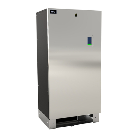
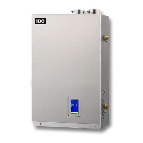
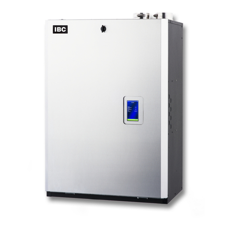
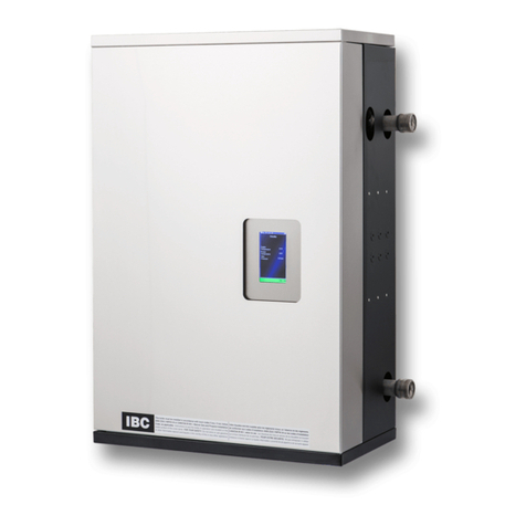
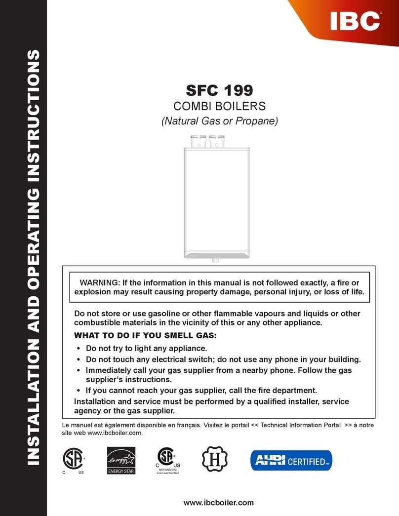
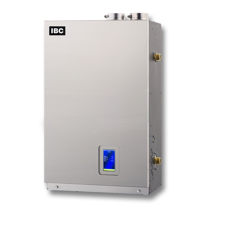
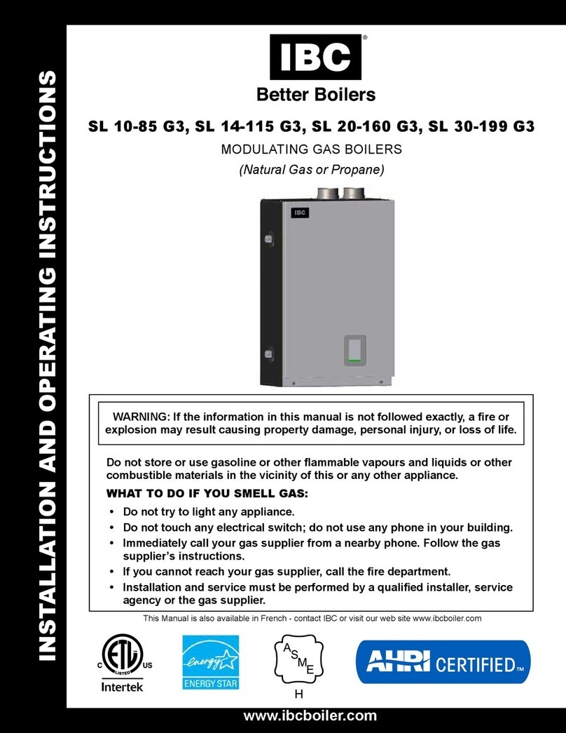
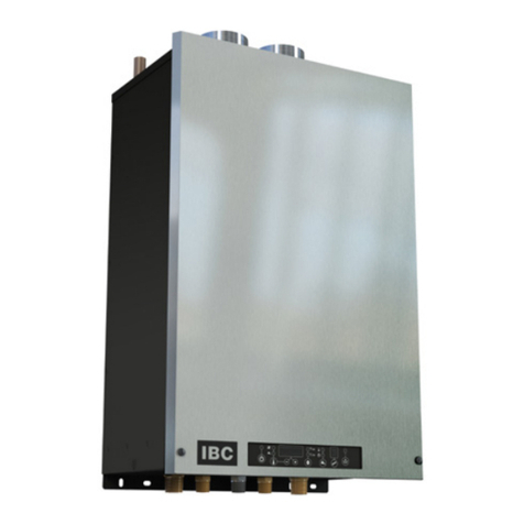
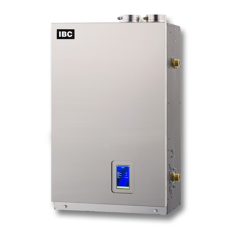
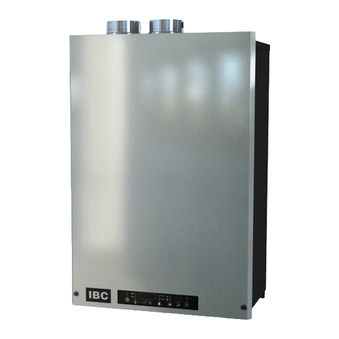
IBC CX Series User manual

INSTALLATION AND
OPERATING MANUAL
WARNING
If the information in this manual is not followed exactly, a fire or explosion may result causing
property damage, personal injury, or loss of life.
Do not store or use gasoline or other flammable vapors and liquids or other combustible
materials in the vicinity of this or any other appliance.
If you smell gas:
Do not try to light any appliance.
Do not touch any electrical switch; do not use any phone in your building.
Immediately call your gas supplier from a nearby phone. Follow the gas supplier’s
instructions.
If you cannot reach your gas supplier, call the fire department.
Installation and service must be performed by a qualified installer, service agency or the gas
supplier.
Residential Combi Boiler
CX 150 (model #ICGFSW1-0150)
CX 199 (model #ICGFSW1-0199)

Water quality
Warning
Water quality has a significant impact on the lifetime and performance of a boiler's heat
exchanger.
Improperly prepared water in a heating circuit may cause damage to the heat exchanger
through fouling or corrosion. Repeated or uncontrolled water fills will increase the potential
for damage.
High levels of dissolved solids or minerals may precipitate out of the fluid onto the hottest part
of the heat exchanger, impairing heat transfer and resulting in overheating and premature
failure. The amount of solids that may form on the heat exchanger will depend on the degree
of hardness and the total water volume in the system. A high water volume system with a low
hardness count may cause as much damage as a system with less volume and higher
hardness, so it is recommended to treat water so as to reduce dissolved solids to the
minimum 10 ppm, and to no more than 30 ppm. Water chemistry allowable limits are as
follows:
TDS 0.6 to 1.75 grains/ gal (10 to 30 ppm)
Acidity pH is to be between 6.6 and 8.5
Chloride is to be less than 125 mg/l
Iron is to be less than 0.3 mg/l
Cu less than 0.1 mg/l
Conductivity is to be less than 400μS/cm at 77°F (25°C)
Important: Ensure that these limits are acceptable for the other water-side components in
the system.
Shipped with the boiler:
1 x Wall mounting bracket, P-9092
1 x Condensate trap assembly
1 x 30 psig pressure relief valve, P-9009
1 x Outdoor temperature sensor, P-9067
6 x ¼" x 2 ½" Lag screws/w flat washers

Contents
Safety information 7
Manual safety markings 7
Important safety instructions 7
Known contaminants 9
Specifications 11
Cabinet dimensions 12
CX 150 dimensions 12
CX 199 dimensions 13
Connection specifications 14
1.0 Introduction 15
1.1 Standard features and benefits 15
1.2 Warranty 16
2.0 Before installation 17
3.0 Installation 19
3.1 Code requirements 19
3.2 Removing an existing boiler 19
3.3 Determining location of the appliance 20
3.3.1 Best installation conditions 21
3.4 Mounting the boiler 21
3.5 Connecting the vent and air intake pipes 23
3.6 Installation clearances 24
3.7 Exhaust venting and air intake 24
3.7.1 Venting code 25
3.7.2 Venting options 25
3.7.3 Exhaust vent material 25
3.7.4 Direct vent 26
3.7.5 Rooftop vent termination 30
3.7.6 Sidewall vent termination 32
3.7.7 Indoor air combustion air intake 40
3.7.8 Combustion air filtration system 41
3.8 Closet installations 42
3.9 Installing a condensate trap 42
3

3.10 Installing a condensate neutralizer 45
3.11 Water piping (space heating) 47
3.11.1 General piping best practices 50
3.11.2 System piping 50
3.12 Water piping (domestic hot water) 59
3.12.1 Domestic hot water system 59
3.12.2 Domestic hot water piping 61
3.13 Gas piping 64
3.13.1 Gas pressure 64
3.14 Electrical connections 65
3.14.1 Power management, quality and electrical protection 66
3.14.2 120VAC line-voltage hook-up 66
3.14.3 Other wiring 68
3.14.4 Thermostat / sensor wiring 68
3.14.5 Wiring zone valves in place of pumps 68
3.14.6 Thermostat heat anticipator 69
4.0 About the boiler controller 71
4.1 Controller 71
4.2 Control interface 72
5.0 Before operating the boiler 73
Important pre-ignition checks 73
Checklist for electrical conditions, ducting and water connections 73
6.0 Boiler operation 75
6.1 Lighting and shutting down the boiler 75
6.2 Testing the ignition safety shutoff 76
6.3 Commissioning 76
6.3.1 Checking a boiler's fuel source 77
6.3.2 Performing a fuel conversion 77
6.3.3 Adjusting the gas valve 78
6.3.4 Testing the LWCO function 82
6.3.5 Testing the Hi-Limit cutoff temperature function 83
7.0 Service and maintenance 85
7.1 Maintenance checklist for homeowner 85
4
Section: Contents

7.2 Maintenance checklist for heating contractor 85
7.2.1 Touchscreen boiler controller 86
7.2.2 General combi boiler maintenance 87
7.3 Replacing the fan, gas valve, and burner 90
7.3.1 Replacing the fan 91
7.3.2 Replacing the gas valve 92
7.3.3 Replacing the burner 94
7.4 Maintenance of the On-Demand DHW block 96
7.4.1 Cleaning the bypass check valve 97
7.4.2 Replacing the bypass actuator 97
7.4.3 Removing the flow sensor 97
7.4.4 Cleaning the water strainer / flow restrictor 97
7.5 Cleaning the sight glass 98
7.6 Cleaning the condensate trap 98
7.7 Ensure door in place 101
8.0 Troubleshooting 103
8.1 Electronic components 103
8.1.1 Temperature sensors 103
8.1.2 Fan 104
8.1.3 Water pressure sensor 104
8.1.4 DHWflow sensor 105
8.1.5 Safety and Ignition Module (SIM+) 105
8.2 Troubleshooting error messages 107
8.2.1 Maximum ignition trials error 108
8.2.2 Hi Limit cut-off temperature error 108
8.2.3 Low Water Cut-off error 108
8.2.4 Aux. Interlock 1 or 2 109
8.3 Miscellaneous touchscreen controller errors 109
8.3.1 Ignition issues 110
8.3.2 Temperature issues 111
8.3.3 Miscellaneous issues 112
8.3.4 Cycling issues 113
Appendices 114
Wiring diagrams 114
8.4 Exploded views of the CX150, CX199 appliance 117
5

Safety information
Manual safety markings
Danger
Points out an immediate hazardous
situation that must be avoided to
prevent serious injury or death.
Warning
Points out a potential hazardous
situation that must be avoided to
prevent serious injury or death.
Caution
Points out a potential hazardous
situation that must be avoided to
prevent possible moderate injury
and/or property damage.
Note
Points out installation, maintenance and
operational notes to enhance efficiency,
longevity and proper operation of the
boiler.
Important safety instructions
Installation, start-up and servicing of IBC boilers must be performed by competent, qualified, licensed
and trained heating technicians.
Failure to read and comply with all instructions and applicable national and local codes may result in
hazardous conditions that could result in property damage and injury to occupants, and in extreme
cases to death. Keep instructions near the air handling appliance for future reference.
7
Safety information

Danger
Should overheating occur or the gas supply fails to shut off, do not turn off or disconnect
the electrical supply to the pump. Instead shut off the gas supply at a location external
to the appliance.
Danger
Do not store or use gasoline or other flammable vapors or liquids in the vicinity of this or
any other appliance. If you smell gas vapors, do not try to operate any appliance - do
not touch any electrical switch or use any phone in the building. Immediately, call the
gas supplier from a phone located remotely. Follow the gas supplier’s instructions, or if
the supplier is unavailable, contact the fire department.
Warning
If the boiler is likely to be exposed to fluid temperatures below 34°F (1°C), use a method
to prevent freezing of condensate. Contact the factory for further information.
Warning
Do not use this boiler if any part has been under water. Immediately call a qualified
service technician to inspect the boiler and to replace any part of the control system and
any gas control that has been under water.
8
Section: Safety information

Warning
Improper installation, adjustment, alteration, service or maintenance can cause property
damage, personal injury, or loss of life. Read and understand the entire manual before
attempting installation, start-up, operation, or service. Installation and service must be
performed only by an experienced, skilled installer or service agency.
Failure to follow all instructions in the proper order can cause personal injury or death.
Read all instructions, including all those contained in component manufacturers’ manuals
before installing, starting up, operating, maintaining, or servicing the appliance.
Warning
Disconnect power supply before any wiring/service is performed. Failure to do so could
result in damage to appliance and/or electric shock.
Caution
The boiler must be installed so that electrical components are not exposed to water during
operation.
Known contaminants
Known Corrosive Contaminants to Avoid
Cements and glues Refrigerant leaks from cracks in coils
Paint or varnish removers Sodium chloride or potassium chloride used for
water softening
Adhesives used to fasten building products
and other similar products
Chemicals in perming solutions
Chlorinated waxes or cleaners Chlorofluorocarbon chemicals found in spray cans
Chlorine-based swimming pool chemicals Antistatic dryer sheets in clothes dryers
Hydrochloric acid or muriatic acid used in
household cleaning and stain removal
Chlorine-type bleaches, detergents, and cleaning
solvents found in household laundry rooms
Calcium chloride used for snow clearing
9
Known contaminants

Intentionally left empty

11
Specifications
Specification CX 150 CX 199
CSA Input (Natural Gas or Propane) 15 - 150 MBH 20 - 199 MBH
CSA Input (Natural Gas or Propane) 4.4 - 44 kW 5.9 - 58.3 kW
CSA Output 14.3 - 138.5 MBH 19.1 - 183.7 MBH
CSA Output 4.2 - 40.6 kW 5.6 - 53.8 kW
DHW - CSA Input (Natural Gas or Propane) 15 - 150 MBH 20 - 199 MBH
DHW - CSA Input (Natural Gas or Propane) 4.4 - 44 kW 5.9 - 58.3 kW
AFUE 95% 95%
Minimum gas supply pressure (natural gas or propane) 4 inch w.c. 4 inch w.c.
Maximum gas supply pressure (natural gas or propane) 14 inch w.c. 14 inch w.c.
Minimum Ambient temperature 32°F / 0°C 32°F / 0°C
Maximum Ambient temperature 122°F / 50°C 122°F / 50°C
Max. relative humidity (non-condensing) 90% 90%
Minimum water temp. 34°F / 1°C 34°F / 1°C
Maximum water temp. (electronic hi-limit) 190°F / 88°C 190°F / 88°C
Max. ΔT - supply/return (electronic fence) 40°F / 22.2°C 40°F / 22.2°C
Max. water temperature lockout limit 201°F / 94°C 201°F / 94°C
Power use (120Vac/60Hz) @ full fire (with internal pump) 224.9 Watts 234.2 Watts
Weight (empty) 100 lbs / 45.4 Kg 113 lbs / 51.3 Kg
Pressure vessel water content 2.79 USG / 10.56 L 3.51USG / 13.29 L
Maximum boiler flow rate 19 USgpm 25 USgpm
Minimum boiler flow rate 3 USgpm 4 USgpm
Maximum boiler operating water pressure* 50 psig 50 psig
Minimum boiler water pressure 8 psig 8 psig
Maximum DHWwater pressure 150 psig 150 psig
Minimum DHWwater pressure 40 psig 40 psig
Relief valve pressure (supplied) 30 psig 30 psig
Approved installation altitude 0 - 12,000' ASL 0 - 12,000' ASL
Maximum equivalent 2" vent length each side (vent & air
intake)
50' N/A
Maximum equivalent 3" vent length each side (vent & air
intake)
170' 100'

Ignition Stages Timings
Fan Pre-purge 15 seconds
Trial for Ignition 4 seconds
Flame Failure Response <0.8 second
Domestic Hot Water Delivery
@ 70°F / 39°C temperature rise
CX150 4.1 GPM
CX199 5.5 GPM
Cabinet dimensions
CX 150 dimensions
Figure 1 Front and side view - CX150
12
Section: Specifications

Figure 2 Top and bottom view - CX150
CX 199 dimensions
Figure 3 Front and side view - CX199
13
CX 199 dimensions

Figure 4 Top and bottom view - CX199
Connection specifications
The following table displays the required connection specifications.
Description CX150 CX199
A Flue Outlet 3" Schedule 40 or 3" PP (80
mm)
3" Schedule 40 or 3" PP (80
mm)
B Combustion Air Inlet 3" Schedule 40 or 3" PP (80
mm)
3" Schedule 40 or 3" PP (80
mm)
C Boiler Return Water Inlet 1" NPT-M 1" NPT-M
D Boiler Supply Water Outlet 1" NPT-M 1" NPT-M
E Condensate Outlet ¾" Hose ¾" Hose
F Gas Inlet ½" NPT-F ½" NPT-F
G DHW outlet (hot water) ¾" NPT-M ¾" NPT-M
H DHW inlet (cold water) ¾" NPT-M ¾" NPT-M
Table 1 Connections
14
Section: Specifications

15
1.0 Introduction
Figure 5 View from the front
1.1 Standard features and benefits
High thermal efficiency
Coordinated Boiler and DHW circuits
Compact
Turn-down ratio 10 to 1
Cascade up to 4 appliances
4 load pump management
Built-in boiler pump
Easy-to-use touchscreen

1.2 Warranty
For residential applications, IBC offers a 5-year warranty on all parts (including the DHWheat
exchanger), against defects in materials or workmanship and failures due to thermal shock only.
IBC offers a combustion heat exchanger (space heating)15-year limited warranty with
registration, according to the following terms:
0-10 years (100% coverage)
11-15 years (25% coverage).
IBC offers a limited combustion heat exchanger warranty with no registration of 0-5 years (100%
coverage).
For commercial applications, IBC offers a 5-year warranty on the combustion heat exchanger
(space heating) and a 2-year warranty on all parts (including the DHWheat exchanger), against
defects in materials or workmanship and failures due to thermal shock only.
To view the full warranty statement for the CXseries, go to ibcboiler.com.
16
Section: Introduction

17
2.0 Before installation
Before installing the appliance, it is important to review and observe the following checklist of
precautions:
Precautions Check
Care must be taken to properly size the boiler for its intended use. Prolonged full fire run
time, over-sizing or under-sizing, and incorrect flow rates through the appliance can lead to
increased maintenance costs, equipment stress and premature failure.
□
Ensure you install the appliance where the combustion air source is not subject to
chemical fouling or agricultural vapors. Exposure to corrosive chemical fumes such as
chlorinated and/or fluorinated hydrocarbons can reduce the life of a boiler. Cleaners,
bleaches, air fresheners, refrigerants, aerosol propellants, dry-cleaning fluids, de-greasers
and paint-removers all contain vapors that can form corrosive acid compounds when
burned in a gas flame. Airborne chlorides such as those released with the use of laundry
detergents are also to be avoided.
□
Locate the appliance where water leakage will not result in damage to the area. If there is
no suitable location, install a suitable drain pan under the boiler. Do not install above
carpeting.
□
At a new construction site, or during renovations, protect the appliance from drywall dust or
other construction-related contaminants. Draw combustion air from a clean source (e.g.,
outdoors) and isolate the boiler from interior dust sources. Do not seal boiler case
openings directly when firing - allow for air circulation and ventilation in the immediate
area.
□
Place the exhaust outlet 12" minimum above the down-turned intake to avoid exhaust re-
ingestion.
□
For sidewall venting options, place the inlet and exhaust terminations on the same side of
the building. The elevation of both pipes can be raised in “periscope style” after passing
through the wall to gain required clearance above grade and snow level.
□
If using the indoor combustion air option, ensure combustion air openings to the boiler
room remain unblocked and free of obstructions.
□
Examine the condensate outlet to ensure proper disposal of condensate will occur during
operation. If condensates are to be discharged into building drain piping materials that are
subject to corrosion, a neutralization package must be used.
□
Ensure that the pressure relief valve is installed with no valves or other means of isolation
between its inlet and the boiler. Make sure the relief valve outlet is piped with unobstructed
piping (minimum ¾" diameter) to a safe discharge location.
□
If the appliance is likely to be exposed to fluid temperatures below 34° F (1° C), a method
of protection to prevent freezing of condensate should be employed. Contact the factory
for further information.
□
When the appliance is in operation, assess the impact of the steam plume typical of a
condensing boiler's exhaust terminal. Generally, intake and exhaust pipes should
terminate at a rooftop or sterile wall location. Boiler condensate is corrosive. Protective
□

Precautions Check
measures must be taken to prevent corrosion damage to metal roofs or other metal
building components in contact with the condensate. Keep exhaust plumes well away from
all building air intakes including those of neighboring properties.
Caution
Care must be taken to properly size the boiler for its intended use. Prolonged full fire run
time, over-sizing or under-sizing, and incorrect flow rates through the boiler can lead to
increased maintenance costs, equipment stress and premature failure.
18
Section: Before installation

19
3.0 Installation
Refer to the Specifications section for dimensional drawings and connection specifications. Use these
drawings to find a suitable location for the appliance.
3.1 Code requirements
The appliances are tested and certified under CSA 4.9 / ANSI Z21.13 (latest edition). Below are the
code requirements for every installation.
Canada US
Conform to local codes, or in the absence of
these, with the latest editions of CAN/CGA
B149.1 and the Canadian Electrical Code Part 1
CSA C22.2 No. 1.
Where required by jurisdiction, installation must
conform to the Standard for Controls and Safety
Devices for Automatically Fired Boilers,
ANSI/ASME CSD-1.
If there is any conflict, follow the more stringent
regulations.
Conform to the current National Fuel Gas Code
ANSI Z223.1 and the National Electrical Code
ANSI/NFPA 70.
Where required by jurisdiction, installation must
conform to the Standard for Controls and Safety
Devices for Automatically Fired Boilers,
ANSI/ASME CSD-1.
If there is any conflict, follow the more stringent
regulations.
Table 2 Code requirements by country
3.2 Removing an existing boiler
When an existing boiler is removed from a common venting system, the common venting system
may be too large for proper venting of the appliances that remain connected to it. When resizing
any portion of the common venting system, use the minimum size according to the appropriate
tables in the National Fuel Gas Code, ANSI Z223.1 - latest edition. In Canada, follow the B149.1
Installation Code.
When removing an existing boiler, the following checks must be carried out for each of the
appliances still connected to the common exhaust system, by operating them one at a time:
Seal any unused opening in the common venting system.
Visually inspect the venting system for proper size and horizontal pitch. Determine that there
is no blockage or restriction, leakage, corrosion and other deficiencies that could cause an
unsafe condition.
(Where practical) Close all building doors and windows such as doors adjacent to
appliances remaining connected to the common venting system and other spaces of the
building.

Turn on clothes dryers and any appliance not connected to the common venting
system.
Turn on any exhaust fans, such as range hoods and bathroom exhausts, so they
will operate at maximum speed. Do not operate a summer exhaust fan.
Close fireplace dampers.
Place in operation the appliance being inspected.
Follow the lighting instructions.
Adjust the thermostat so that the appliance operates continuously.
After determining that each appliance remaining connected to the common venting
system properly vents when tested as outlined above, return doors, windows, exhaust
fans, fireplace dampers and any other gas-burning appliance to their previous condition.
Any improper operation of the common venting system should be corrected, so the
installation conforms with the National Fuel Gas Code, ANSI Z223.1 - latest edition. In
Canada, all installations must conform with the current CAN/CGA - B149.1-10
Installation Code and/or local codes.
3.3 Determining location of the appliance
The boilers are designed and approved for indoor installation (wall or rack mounting) in areas
such as an alcove, basement, or utility room. These areas should have a surrounding
temperature of 32 °F (0°C) to 122 °F (50 °C) and less than 90% relative humidity.
Danger
Do not common vent appliances with other existing appliances or with a new
appliance.
Warnings
Keep the area around a boiler clear of combustible materials, gasoline, and
other flammable vapors and liquids.
Ensure combustion air is not drawn from areas containing corrosive air such as
swimming pools or spas, including air directly next to outdoor pools and spas.
Ensure that a boiler is not exposed to water leaks from piping or components
located overhead, including condensation from uninsulated cold water lines
overhead.
Protect the gas ignition system components from water (dripping, spraying,
rain, etc.) during appliance operation and when servicing (pump replacement,
condensate trap servicing, control replacement, etc.).
Ensure that combustible materials do not make contact with exposed water
piping and associated components (relief valves, circulators, etc.). Check local
codes for required clearances and/or provide adequate insulation.
20
Section: Installation
This manual suits for next models
4
Table of contents
Other IBC Boiler manuals

IBC
IBC P-749B Quick start guide

IBC
IBC SL 20-160 G3 User manual

IBC
IBC SL Series Installation instructions

IBC
IBC VX 110 User manual

IBC
IBC SL SERIES Guide

IBC
IBC SL 10-85 G3 User manual

IBC
IBC VX Series Installation instructions
IBC
IBC SL 40-399 G3 User manual

IBC
IBC EX 850 Guide

IBC
IBC SL SERIES Installation instructions
Popular Boiler manuals by other brands

Wolf
Wolf ComfortLine CHK Installation and maintenance instructions

Express
Express AS18 User instructions

Knight
Knight 51 Service manual

Vaillant
Vaillant GA100CS SERIES Installation and service manual

Vaillant
Vaillant ecoTEC exclusive 835 Installation and maintenance instructions

KSM-Stoker
KSM-Stoker KSM-Multistoker 240 XL instructions