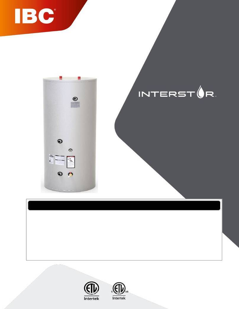
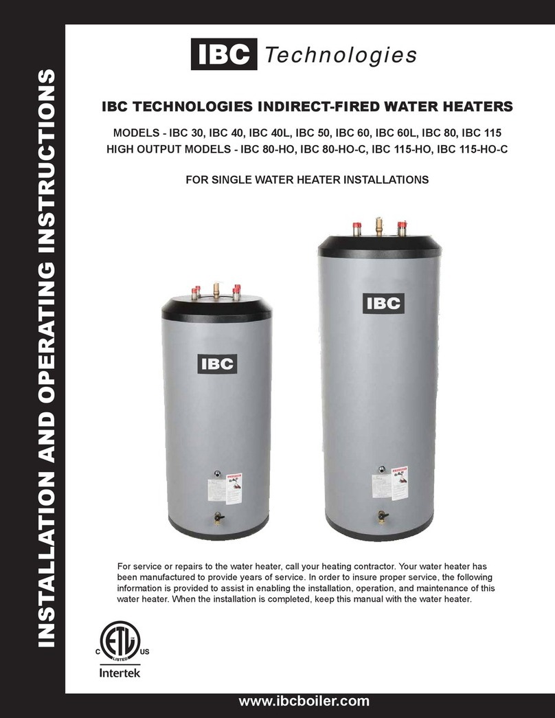
IBC IWT Series User manual

Installation and
Operating Manual
IWT SERIES
Indirect Water Heaters
IWT 40 IWT 80-Max
IWT 50 IWT 119-Max
IWT 65
IWT 80
IWT 119
CAUTION:
The heat transfer medium must be water or other nontoxic fluid having a toxicity rating
or Class of 1, as listed in Clinical Toxicology of Commercial Products, 5th edition.
The pressure of the heat transfer medium must be limited to a maximum of 30 PSIG by
an approved safety or relief valve.


1
Contents
Safety information 3
Manual safety markings 3
Important safety instructions 3
Specifications 6
Recovery rate 10
Pressure drop vs boiler flow 13
1.0 Introduction 14
1.1 Standard components 14
1.2 Pressure relief valve 14
1.3 Conformity 14
1.4 Standards 14
2.0 Pre-installation overview 15
2.1 Installation checklist 15
2.2 System zone control 16
2.3 Priority or non-priority for hot water 17
2.3.1 Option 1 – Priority 17
2.3.2 Option 2 – Non-priority 17
2.4 Locating the water heater 18
2.5 Temperature and pressure relief valve 18
2.6 Additional recommended components 19
2.7 Removing the existing domestic water heating system 19
2.8 Water quality 20
3.0 Piping 21
3.1 Domestic water piping 21
3.2 Boiler water piping 22
3.3 Zone circulator system 22
3.4 Zone valve system (residential only) 23

4.0 Electrical 24
4.1 Temperature sensor 24
4.2 Aquastat 26
5.0 Operation 27
5.1 Important terms explained 27
5.2 Start-up 27
5.3 Temperature adjustment 27
6.0 Maintenance 29
6.1 Chemical cleaning of the heating coil 29
6.1.1 Flushing the tank 29
6.1.2 Refilling the tank 30
7.0 Troubleshooting 31
8.0 Diagrams 33
Domestic water piping 36
Revision history 37
2
Section: Contents

3
Safety information
Manual safety markings
Danger
Points out an immediate hazardous
situation that must be avoided to
prevent serious injury or death.
Warning
Points out a potential hazardous situation
that must be avoided to prevent serious
injury or death.
Caution
Points out a potential hazardous
situation that must be avoided to
prevent possible moderate injury
and/or property damage.
Note
Points out installation, maintenance and
operational notes to enhance efficiency,
longevity and proper operation of your
water heater.
Important safety instructions
Failure to read and comply with all instructions and applicable national and local codes may result in
hazardous conditions that could result in property damage and injury to occupants, and in extreme cases to
death. Keep instructions near the water heater for future reference.
When using electrical appliances, follow safety precautions to reduce the risk of fire, electric shock, or injury
to persons, including:
Install or locate the water heater only in accordance with the provided installation instructions.
Use the indirect water heater only for its intended use as described in this manual.
As with any appliance, close supervision is necessary when used by children.
Do not operate the indirect water heater if it is not working properly, or if it has been damaged or
dropped.
Installation, start-up and servicing of IBC's indirect water heaters must be done with care and
attention, and should only be performed by competent, qualified, licensed and trained plumbing and
heating technicians. Contact your nearest authorized service facility for examination, repair, or
adjustment.

Danger
Do not store or use gasoline or other flammable vapors or liquids in the vicinity of this or any
other appliance. If you smell gas vapors, do not try to operate any appliance - do not touch
any electrical switch or use any phone in the building. Immediately, call the gas supplier from
a phone located remotely. Follow the gas supplier’s instructions, or if the supplier is
unavailable, contact the fire department.
Warning
Improper installation, adjustment, alteration, service or maintenance can cause property
damage, personal injury, or loss of life. Read and understand the entire manual before
attempting installation, start-up, operation, or service. Installation and service must be
performed only by an experienced, skilled installer or service agency.
The water heater contains very hot water under high pressure. Do not unscrew any pipe
fittings or attempt to disconnect any components of this water heater without positively
assuring that the water is cool and has no pressure. Always wear protective clothing and
equipment when installing, starting up or servicing this water heater to prevent scalding
injuries. Do not rely on the pressure and temperature gauges to determine the temperature
and pressure of the water heater. This water heater contains components that become very
hot when the boiler is operating. Do not touch any components unless they are cool.
Failure to follow all instructions in the proper order can cause personal injury or death. Read
all instructions, including all those contained in component manufacturers’ manuals before
installing, starting up, operating, maintaining, or servicing the water heater.
4
Section: Safety information

Caution
To reduce the risk of excessive pressures and temperatures in this water heater, install
temperature and pressure protective equipment required by local codes, but no less than a
combination temperature relief valve certified by a nationally recognized testing laboratory that
maintains periodic inspection of production of listed equipment or materials, as meeting the
requirements for Relief Valves and Automatic Shutoff Devices for Hot Water Supply Systems,
ANSI Z21.22-latest edition.
This valve must be marked with a maximum set pressure not to exceed the marked working
pressure of the water heater. Install the valve into an opening provided and marked for this
purpose in the water heater, and orient it or provide tubing so that any discharge from the valve
will exit only within 6 inches above a suitable drain. The discharge opening must not be blocked
or reduced in size under any circumstances. The heat transfer medium must be water or other
non-toxic fluid having a toxicity rating or class of 1, as listed in clinical Toxicology of Commercial
Products, latest edition.
Installation, start-up and servicing of IBC boilers and water heaters must be done with due care
and attention, and should only be performed by competent, qualified, licensed and trained
heating technicians.
Note
The instructions in the manual focus almost entirely on installations where the IBC indirect water
heater is used with a compatible IBC boiler. Installers and designers must read the IBC boiler
manuals and application notes to ensure that finished installations operate in harmony, and
deliver optimal energy savings and efficiency.
Although IBC indirect water heaters are compatible with most other boiler makes, installers and
designers must tailor their designs to the specific control, operational and installation
requirements of alternative boilers. This equipment must be installed according to the installation
regulations of the local area. These regulations must be carefully followed in all cases. Authorities
having jurisdiction must be consulted before the installations are made.
All wiring on water heaters must adhere to the National Electrical Code and/or local regulations.
5
Safety information

6
Specifications
The table below displays information on dimensions and weights to help with installing and connecting the
tank. Diagrams provided in this section contain connection sizes.
Specification IWT 40
(150L)
IWT 50
(200L)
IWT 65
(250L)
IWT 80
(302L)
IWT 119
(425L)
Max. Operating Pressure 150 psi 150 psi 150 psi 150 psi 150 psi
Height (inches/mm) 45.2 / 1148 57 / 1448 54.5 / 1384 64.5 / 1638 65.7 / 1669
Diameter (inches/mm) 22 / 559 22 / 559 24.5 / 622 24.5 / 622 28 / 711
Operation at outlet water
temperature ° F / ° C
180 / 82 180 / 82 180 / 82 180 / 82 180 / 82
Gross tank volume -
USG / Liters
40 / 151 53 / 201 66 / 250 79.3 / 300 119 / 450
Net tank volume -
USG / Liters
38.3 / 145 50.7 / 192 63.9 / 242 77.4 / 293 113 / 426
Weight - empty Lbs / kg 100 / 45.3 127 / 57.6 145 / 65.8 166 / 75 230 / 104
Shipping weight -
Lbs / kg
120 / 54.4 145 / 65.7 170 / 77 193 / 87.5 275 /125
Domestic conn. size ¾" M ¾" M ¾"M 1" M 1½" M
First hour delivery - Gal/Hr * 204 259 309 356 474
Continuous Draw @ - Gal/Hr* 170 217 259 287 373
Boiler Output Required -
Btu/Hr*
120,000 140,000 180,000 200,000 240,000
Minimum flow rate - GPM 14 14 14 14 14
Heating coil pressure drop - Ft.
Hd.*
6.2 7 7.5 10.1 11.8
Coil heat transfer area - Ft.2* 8.1 10.2 11.4 13.4 10.2
Certified - water heater
Certified - low lead
Table 1 Dimensions and weights: IWT 40, IWT 50, IWT 65, IWT 80, IWT 119
*Based on 180⁰F boiler supply and 58⁰F entering cold water

Specification IWT 80-Max
(302L)
IWT 119-Max
(425L)
Max. Operating Pressure 150 psi 150 psi
Dimensions Height
(inches/mm)
64.5 / 1638 65.7 / 1669
Diameter (inches/mm) 24.5 / 622 28 / 711
Operation at outlet water
temperature ° F / ° C
180 / 82 180 / 82
Gross tank capacity -
USG / Liters
79.3 / 300 119 / 450
Net tank capacity -
USG / Liters
75.0 / 284 111 / 419
Weight - empty Lbs / kg 188 / 85 246 /111
Shipping weight - Lbs / kg 201 / 91 290 / 131
Domestic conn. size 1½" M 1½" M
First hour delivery - Gal/Hr * 719 753
Continuous Draw @ - Gal/Hr * 653 653
Boiler Output Required -
Btu/Hr *
420,000 420,000
Minimum flow rate - GPM 25 25
Heating coil pressure drop -
Ft. Hd.*
16.7 16.7
Coil Heat Transfer Area - Ft.2* 27.4 27.4
Certified - water heater
Certified - low lead
Table 2 Dimensions and weights: IWT 80-Max, IWT 119-Max
*Based on 180⁰F boiler supply and 58⁰F entering cold water
7
Section: Specifications

Figure 1 Tank dimensions - IWT 40, IWT 50, IWT 65
IWT 40 IWT 50 IWT 65
A=Height (inches/mm) 45.2 / 1148 57 / 1448 54.5 / 1384
B=Diameter (inches/mm) 22 / 559 22 / 559 24.5 / 622
¾" M NPT Hot water outlet
¾" M NPT Cold water outlet
¾" F NPT T&P relief valve
1" M NPT In from boiler (boiler supply)
Sensor well
1" M NPT Out to boiler (boiler return)
½" F NPT (tank drain)
8
Specifications

Figure 2 Tank dimension: IWT 80, IWT 80-Max Figure 3 Tank dimension: IWT 119, IWT 119-Max
IWT 80 IWT 80-Max IWT 119 IWT 119-Max
A=Height (inches) 64.5 / 1638 64.5 / 1638 65.7 / 1669 65.7 / 1669
B=Diameter (inches) 24.5 / 622 24.5 / 622 28 / 711 28 / 711
IWT 80 IWT 80-Max IWT 119 IWT 119-Max
¾" F NPT T&P Relief
valve
1" F NPT T&P Relief
valve
1" F NPT T&P Relief
valve
1" F NPT T&P Relief
valve
1" M NPT Hot water
outlet
1½" M NPT Hot water
outlet
1½" M NPT Hot water
outlet
1½" M NPT Hot water
outlet
1" M NPT In from boiler
(boiler supply)
1½" M NPT In from
boiler (boiler supply)
1½" M NPT In from
boiler (boiler supply)
1½" M NPT In from
boiler (boiler supply)
Sensor well Sensor well Sensor well Sensor well
1" M NPT Out to boiler
(boiler return)
1½" M NPT Out to
boiler (boiler return)
1½" M NPT Out to
boiler (boiler return)
1½" M NPT Out to
boiler (boiler return)
½" F NPT (tank drain) ½" F NPT (tank drain) ½" F NPT (tank drain) ½" F NPT (tank drain)
1" M NPT Cold water
inlet
1½ M NPT Cold water
inlet
1½" M NPT Cold water
inlet
1½" M NPT Cold water
inlet
9
Section: Specifications

Recovery rate
IWT 40 (135 °F)
Boiler
Output
(BTU/Hr)
Boiler Flow = 14 gpm / 160 °F Boiler Flow - 14 gpm / 180°F
1st Hour Rating
(Gal/Hr)
Continuous rating
(Gal/Hr) 58°F entering
cold water
1st Hour Rating
(Gal/Hr)
Continuous rating
(Gal/Hr) 58°F entering
cold water
50,000 97 60 114 78
60,000 108 72 129 93
80,000 132 96 159 124
100,000 155 120 190 156
120,000 166 131 204 170
140,000 166 131 204 170
160,000 166 131 204 170
Table 3 Recovery rates - IWT 40
IWT 50 (135 °F)
Boiler
Output
(BTU/Hr)
Boiler Flow = 14 gpm / 160 °F Boiler Flow - 14 gpm / 180°F
1st Hour Rating
(Gal/Hr)
Continuous rating
(Gal/Hr) 58°F entering
cold water
1st Hour Rating
(Gal/Hr)
Continuous rating
(Gal/Hr) 58°F entering
cold water
50,000 107 60 124 78
60,000 118 72 139 93
80,000 141 96 169 124
100,000 165 120 199 156
120,000 188 144 230 187
140,000 211 167 259 217
160,000 211 167 259 217
Table 4 Recovery rates - IWT 50
10
Recovery rate

IWT 65 (135 °F)
Boiler
Output
(BTU/Hr)
Boiler Flow = 14 gpm / 160 °F Boiler Flow - 14 gpm / 180°F
1st Hour Rating
(Gal/Hr)
Continuous rating
(Gal/Hr) 58°F entering
cold water
1st Hour Rating
(Gal/Hr)
Continuous rating
(Gal/Hr) 58°F entering
cold water
50,000 116 60 134 78
60,000 128 72 149 93
80,000 151 96 179 124
100,000 174 120 209 156
120,000 198 144 239 187
140,000 221 168 269 218
160,000 244 192 300 249
180,000 252 199 309 259
Table 5 Recovery rates - IWT 65
IWT 80 (135 °F)
Boiler
Output
(BTU/Hr)
Boiler Flow = 14 gpm / 160 °F Boiler Flow - 14 gpm / 180°F
1st Hour Rating
(Gal/Hr)
Continuous rating
(Gal/Hr) 58°F entering
cold water
1st Hour Rating
(Gal/Hr)
Continuous rating
(Gal/Hr) 58°F entering
cold water
50,000 136 60 153 78
60,000 147 72 168 93
80,000 171 96 198 124
100,000 194 120 228 156
120,000 217 144 259 187
140,000 240 168 289 218
160,000 263 192 319 249
180,000 287 216 349 280
200,000 292 221 356 287
Table 6 Recovery rates - IWT 80
11
Section: Specifications

IWT 119 (135 °F)
Boiler
Output
(BTU/Hr)
Boiler Flow = 14 gpm / 160 °F Boiler Flow - 14 gpm / 180°F
1st Hour Rating
(Gal/Hr)
Continuous rating
(Gal/Hr) 58°F entering
cold water
1st Hour Rating
(Gal/Hr)
Continuous rating
(Gal/Hr) 58°F entering
cold water
50,000 170 60 187 78
60,000 181 72 202 93
80,000 204 96 232 124
100,000 228 120 262 156
120,000 251 144 293 187
140,000 274 168 323 218
160,000 297 192 353 249
180,000 321 216 383 280
200,000 344 240 413 311
220,000 367 263 443 342
240,000 390 287 474 373
Table 7 Recovery rates - IWT 119
IWT 80 Max (135 °F)
Boiler
Output
(BTU/Hr)
Boiler Flow = 25 gpm / 160 °F Boiler Flow - 25 gpm / 180°F
1st Hour Rating
(Gal/Hr)
Continuous rating
(Gal/Hr) 58°F entering
cold water
1st Hour Rating
(Gal/Hr)
Continuous rating
(Gal/Hr) 58°F entering
cold water
200,000 322 249 383 311
220,000 347 274 414 342
240,000 371 299 444 373
250,000 383 311 459 389
300,000 444 373 536 467
350,000 505 435 612 544
380,000 542 473 658 591
400,000 566 498 688 622
420,000 591 523 719 653
Table 8 Recovery rates - IWT 80-Max
12
Recovery rate

IWT 119 Max (135 °F)
Boiler
Output
(BTU/Hr)
Boiler Flow = 25 gpm / 160 °F Boiler Flow - 25 gpm / 180°F
1st Hour Rating
(Gal/Hr)
Continuous rating
(Gal/Hr) 58°F entering
cold water
1st Hour Rating
(Gal/Hr)
Continuous rating
(Gal/Hr) 58°F entering
cold water
200,000 357 249 418 311
220,000 381 274 448 342
240,000 405 299 479 373
250,000 418 311 494 389
300,000 479 373 570 467
350,000 539 435 646 544
380,000 576 473 692 591
400,000 600 498 722 622
420,000 625 523 753 653
Table 9 Recovery rates - IWT 119-Max
Pressure drop vs boiler flow
Pressure Drop (ft of water) vs Boiler Flow
Model 10 gpm 14 gpm 25 gpm
IWT 40 3.3 6.2 -
IWT 50 4.0 7.0 -
IWT 65 4.4 7.5 -
IWT 80 5.4 10.1 -
IWT 119 6.5 11.8 -
IWT 80 Max 8.0 14.4 16.7
IWT 119 Max 8.0 14.4 16.7
Table 10 Pressure drop vs boiler flow - all models
13
Section: Specifications

14
1.0 Introduction
The IBC Indirect water heater (IWT) is shipped with a 10KΩ sensor. An aquastat can be used to create a call
for heat with most boilers. The 10KΩ sensor will work with all IBC boilers. Ensure compatibility if using the
sensor with other boiler manufacturers' equipment.
1.1 Standard components
Items supplied with the indirect water heater include:
10KΩ sensor
Tank drain valve (installed)
Not Included:
Temperature and pressure relief valve
Aquastat
1.2 Pressure relief valve
Supply a temperature and pressure relief valve rated to ANSI Z21.22 and that has a rating greater than the
gross input of the boiler connected to the water heater. For more information, see Temperature and pressure
relief valve on page 18.
1.3 Conformity
Inspect shipment carefully for signs of damage. All equipment is carefully inspected and packed. IBC’s
responsibility ceases upon delivery of the water heater to the carrier. Any claims for damage or shortage,
must be filed immediately against the carrier. No claims for variances or shortages will be allowed by the
manufacturer.
1.4 Standards
Installation must conform to the requirements of the authority having jurisdiction. In the absence of such
requirements, the installation must conform to the National Plumbing Code and the National Electrical Code
ANSI/NFPA No. 70, current edition.
For drinking water system components follow the Lead Content NSF/ANSI 372:2016 code.
Appliances for use with an external heat source must follow the 1992/06/01 IAS U.S code.

15
2.0 Pre-installation overview
Note
Local inspection authorities may not accept the indirect water heater due to jurisdictional
demands such as double-wall heat exchanger requirements, local, or state registration
requirements. Before installing the indirect water heater, you must check that local authorities will
accept this equipment.
2.1 Installation checklist
The following checklist will help with water heater, boiler, and circulator sizing.
Checklist Check
Water heater sizing Choose the water heater model based on the expected water
usage for the given site. The average residence with one
shower or more will require a Model 40 or larger. Factors that
increase water demand dramatically include high flow shower
heads, hot tubs, and the use of more than one shower at a time.
Increase the tank size if these factors are present.
Carefully review the IBC water heater Specifications on page 6,
and consult ASHRAE sizing guides and other reliable
references. Dimensions, weights, ratings, and capacities are
outlined in the Specifications tables (see Table 1 and Table 2 ).
□
Boiler sizing The water heater will provide the rated performance only if it is
used with a boiler with a heating capacity of at least as much as
the capacity ratings in Table 1 and Table 2 . If the boiler has
less capacity, the water heating output will be reduced.
□
Circulator sizing Refer to Table 1 and Table 2 for the flow through the water
heater coil and the pressure drop at minimum flow. Calculate
the pressure drop across all piping and fittings connected to the
water heater zone. Be sure to include all zone valves, check
valves, and shut-off valves. We recommend piping the water
heater zone with minimum 1" pipe around the entire loop on
typical small residential sites.
□

2.2 System zone control
Caution
To avoid water damage from leaks, install a drain pan under the water heater unless it is
located where leaks will not cause property damage. See Figure 8 .
If unable to direct discharge from a T&P relief valve into a drain or into an area where water
damage will not occur, install a drain pan capable of draining away the full, continuous
discharge flow of the relief valve.
You must install the water heater as a separate zone from the space heating system. The water heating
zone’s piping and circulator must be sized for the minimum flow rate with all the zones in use and a
maximum flow with only the water heater in use. The best method for zone control is the use of circulators.
The three most common systems are:
1. Zone Circulators. Space heating zones use a circulator for each zone, and the water heater is
controlled with an additional circulator.
2. Hybrid System. Space heating zones use zone valves for each zone, and the water heater is
controlled with an additional circulator. See Figure 4 .
3. Zone Valves. Space heating zones use zone valves for each zone, and the water heater is
controlled with an additional zone valve. Select a valve with a low pressure drop and adequate
pipe size to ensure maximum flow.
16
Section: Pre-installation overview

Warning
During operation, the temperature and pressure relief valve may discharge large amounts of
steam and/or hot water. To reduce the potential for bodily injury and property damage, a
discharge line must be installed that:
Is connected from the valve outlet with no intervening valve, and directed downward to a
safe point of discharge.
Allows complete drainage of both the valve and the discharge line.
Is independently supported and securely anchored to avoid applied stress on the valve.
Is as short and straight as possible.
Terminates freely to atmosphere where any discharge is clearly visible and at no risk of
freezing.
Terminates with a plain end, which is not threaded.
Is constructed of a material suitable for exposure to temperatures of 375°F or greater.
Is, over its entire length, of a pipe size equal to or greater than that of the valve outlet.
! Do not cap, plug, or obstruct the discharge pipe outlet.
2.3 Priority or non-priority for hot water
2.3.1 Option 1 – Priority
The demand for space heating is interrupted until the hot water demand is satisfied. This option provides the
maximum delivery of hot water. You can easily configure IBC boilers to operate the hot water demand as a
priority load. Priority is recommended when:
1. The boiler output is less than 100,000 Btu per hour, or
2. The boiler output required to satisfy the hot water demand is more than 50% of the boiler output
needed to satisfy the space heating demand, or when
3. An interruption in space heating can be tolerated during long domestic hot water draws.
When using the Priority option, the preferred strategy is to use a dedicated load circulator for domestic hot
water generation. In most cases, the delay in space heating will not be noticed because of the rapid recovery
of the water heater.
2.3.2 Option 2 – Non-priority
The boiler output is divided between space heating and water heating. Heating of domestic hot water can be
reduced during simultaneous space and water heating demands.
17
2.3 Priority or non-priority for hot water

The maximum amount of reduction depends on the:
Boiler output
Number of space heating zones calling
Space heating target water temperature, and the
Amount of boiler water flow split between the space heating and zones and the water heater zone.
2.4 Locating the water heater
Locate the water heater in an area where water leakage from the tank or connections will not result in
damage to areas adjacent to the water heater or to lower floors of the structure. If unable to find an
appropriate location, you must install a suitable drain pan under the water heater and connect the drain
pan to a drain.
To enable easy access for servicing, install the water heater as close to the boiler as far as is practicable.
The appliance is designed for installation on combustible flooring and in alcoves, closets, etc.
Surface Distance from Combustibles For Service
Front 1" 24"
Rear, Right and Left Sides 1" 1"
Top 1" 1"
Bottom 0" 0"
Table 11 Clearances from heater jacket
2.5 Temperature and pressure relief valve
1. Supply a temperature and pressure relief valve rated to ANSI Z21.22 and that has a rating greater
than the gross input of the boiler connected to the water heater.
2. Install the temperature and pressure relief valve in the tapping on the side of the tank labeled
"Relief Valve".
3. Pipe the outlet of the relief valve to an appropriate location (floor drain or drain pan) terminating
within 6" of an appropriate drain location. Pipe the relief valve piping down toward the outlet of the
piping, so that the piping and the valve can fully drain. Never terminate the relief valve piping
outdoors where it may freeze.
4. Do not install a shut off valve between the water tank and the relief valve. Do not plug the
outlet of the relief valve.
18
Section: Pre-installation overview
This manual suits for next models
7
Table of contents
Other IBC Water Heater manuals
Popular Water Heater manuals by other brands

Vaillant
Vaillant uniSTOR operating instructions

Lochinvar
Lochinvar CH 600 PG CE Installation, commissioning, user & maintenance instructions

Bosch
Bosch Evolution 500 instruction manual

Prevail-Catv
Prevail-Catv EN Series Installation guide & operation manual

Webasto
Webasto Thermo Top C installation instructions

Modena
Modena Veloce Series User manual book