IBM SelectaDock II User manual

IBM ThinkPad
SelectaDock II
User's Guide


IBM ThinkPad
SelectaDock II
User's Guide
IBM

Note
Before using this information and the product it supports, be sure to read the general information in
Appendix D.
First Edition (August 1996)
The following paragraph does not apply to the United Kingdom or any country where such
provisions are inconsistent with local law:
INTERNATIONAL BUSINESS MACHINES CORPORATION PROVIDES THIS PUBLICATION “AS IS”
WITHOUT ANY WARRANTY OF ANY KIND, EITHER EXPRESS OR IMPLIED, INCLUDING, BUT NOT
LIMITED TO, THE LIMITED WARRANTIES OF MERCHANTABILITY OR FITNESS FOR A PARTICULAR
PURPOSE. Some states do not allow disclaimer or express or implied warranties in certain transactions;
therefore, this statement may not apply to you.
This publication could include technical inaccuracies or typographical errors. Changes are periodically
made to the information herein; these changes will be incorporated in new editions of the publication. IBM
may make improvements or changes in the products or the programs described in this publication at any
time.
Requests for technical information about IBM products should be made to your IBM Authorized Dealer or
your IBM Marketing Representative.
Some parts of this manual are taken or adopted from the Adaptec EZ-SCSI documentation with
permission from Adaptec, Inc. IBM Corporation has rights and responsibility for this manual.
Copyright International Business Machines Corporation 1996. All rights reserved.
Portions of this manual are Copyright 1993, 1996 Adaptec, Inc. All rights reserved.
Note to U.S. Government Users — Documentation related to restricted rights — Use, duplication or
disclosure is subject to restrictions set forth in GSA ADP Schedule Contract with IBM Corp.

Contents
Information Notices . . . . . . . . . . . . . . . . . . . . . . . . . . . . vi
Electrical Safety Notices ......................... vi
About This Book ............................ ix
Chapter 1. Introduction . . . . . . . . . . . . . . . . . . . . . . . . 1
Standard Features . . . . . . . . . . . . . . . . . . . . . . . . . . . . 4
Unpacking the Box ............................ 5
Locating the Features .......................... 6
SelectaDock II Status Indicators ................... 11
Chapter 2. Using the SelectaDock System ........... 13
Setting Up Your ThinkPad System .................. 14
Attaching or Removing the SelectaDock Base to or from the
Docking Station . . . . . . . . . . . . . . . . . . . . . . . . . . . . 18
Modes of Operation .......................... 23
Configuring the Computer for Docking and Undocking ...... 25
Cold Docking and Undocking ..................... 26
Hot or Warm Docking and Undocking ................ 28
Chapter 3. Installing and Removing Options .......... 33
Handling Internal Options ....................... 34
Installing or Removing a Drive in the UltraBay Tray ........ 35
Installing or Removing a Drive in the 1-Inch-High Drive Space . 44
Installing or Removing a Drive in the Half-Height Drive Space .. 49
Installing or Removing the PCI/ISA Adapter Card ......... 54
Installing or Removing a PC Card .................. 59
Using the MIDI/Joystick Port ..................... 61
Connecting External SCSI Devices ................. 63
Releasing the Latch .......................... 64
IDE Setup . . . . . . . . . . . . . . . . . . . . . . . . . . . . . . . . 64
Chapter 4. Using the Security Features ............. 67
Using the Security Key Lock ..................... 68
Securing the SelectaDock Docking System with the MicroSaver
Lock . . . . . . . . . . . . . . . . . . . . . . . . . . . . . . . . . . 72
Chapter 5. Setting Up for Sharing a SelectaDock System .. 73
Overview of Sharing a System .................... 74
Setup Procedure . . . . . . . . . . . . . . . . . . . . . . . . . . . . 75
Copyright IBM Corp. 1996 iii

Chapter 6. Using the SCSI Controller .............. 79
Assigning SCSI IDs .......................... 80
Terminating the SCSI Port ...................... 80
SCSI Software Support ........................ 81
Chapter 7. Solving Problems . . . . . . . . . . . . . . . . . . . 83
Isolating a Problem Unit ........................ 85
Attention Indicator . . . . . . . . . . . . . . . . . . . . . . . . . . . 90
How to Run Tests ........................... 92
Troubleshooting Guide . . . . . . . . . . . . . . . . . . . . . . . . . 94
Getting Service . . . . . . . . . . . . . . . . . . . . . . . . . . . . 108
Appendix A. Tips, Hints, and Limitations ........... 109
Drive Letters . . . . . . . . . . . . . . . . . . . . . . . . . . . . . 110
Selecting Startup Drives ....................... 110
Using a Diskette Drive ........................ 113
Using Multiple Configurations for DOS .............. 113
If Multiple Configurations Are Not Supported ........... 114
Operating System Hints ....................... 114
Parameter Consideration for the Socket Service ......... 115
I/O Address for the Game Port ................... 115
Adapter Connector for Ethernet Adapter Card .......... 115
Limitations for Using ISA or PCI Adapter Option Cards ..... 116
Limitations for Suspend and Resume Functions ......... 116
Wrapping Around Cables ...................... 117
Using Windows NT .......................... 117
Turning the Computer and the SelectaDock Docking System On
and Off . . . . . . . . . . . . . . . . . . . . . . . . . . . . . . . . 117
Charging the Battery Pack of the Computer ........... 117
Limitations for Allocating I/O Resources X'330' to X'333'.. 117
Appendix B. Using the SCSI Support Software ....... 119
Installing EZ-SCSI for Windows .................. 121
Installing EZ-SCSI for DOS ..................... 122
Reinstalling Adaptec EZ-SCSI ................... 123
Viewing More Online Information .................. 124
Formatting Utilities . . . . . . . . . . . . . . . . . . . . . . . . . . 124
Appendix C. Specifications . . . . . . . . . . . . . . . . . . . 137
Physical Characteristics . . . . . . . . . . . . . . . . . . . . . . . 137
iv IBM ThinkPad SelectaDock II User's Guide

Environmental Requirements . . . . . . . . . . . . . . . . . . . . 138
Electrical Characteristics . . . . . . . . . . . . . . . . . . . . . . 139
External Interfaces . . . . . . . . . . . . . . . . . . . . . . . . . . 139
IBM Power Cords ........................... 140
Appendix D. Product Warranty, Notices, and Statements . 143
Federal Communications Commission (FCC) Statement .... 148
Canadian Department of Communications Compliance Statement 148
Avis de conformité aux normes du ministère des
Communications du Canada ................... 149
European Community (EC) Directive Conformance Statement . 149
Index . . . . . . . . . . . . . . . . . . . . . . . . . . . . . . . . . . 151
Contents v
Information Notices
This user's guide contains notices that relate to specific information or
text.
DANGER
Indicates situations that are potentially lethal or extremely hazardous
to you. It appears in text
before
the instruction or situation that could
be dangerous.
CAUTION
Indicates situations that are potentially hazardous to you. It also
appears in text
before
the instruction or situation that could be
hazardous.
ATTENTION
Indicates possible damage to programs, devices, system, or data. An
attention notice appears before the related instruction or situation in
which possible damage could occur.
Important
Provides important information or guidelines that you should be aware
of.
Note
Provides hints, tips, guidance, or advice.
Electrical Safety Notices
DANGER
Before you install or remove the option, unplug the power cord.
vi IBM ThinkPad SelectaDock II User's Guide

DANGER
Power is controlled by the power switch of the computer. In an
emergency, turn off the power by unplugging the SelectaDock II
power cord. The electrical outlet should be near the SelectaDock
II and should be easily accessible.
DANGER
To avoid a shock hazard:
Do not connect or disconnect any cables or perform
installation, maintenance, or reconfiguration of this product
during an electrical storm.
The power cord must be connected to an outlet that has been
properly wired and grounded according to your local wiring
rules.
This equipment must have an earth ground.
Apparaten skall anslutas till jordat uttag när den ansluts till ett
nätverk.
Jordet stikkontakt skal benyttes når apparatet tilkobles
datanett.
Laite on liitettävä maadoitettuun pistorasiaan.
Any equipment to which this product is attached to must also
be connected to an outlet that has been properly wired and
grounded according to your local wiring rules.
Contents vii
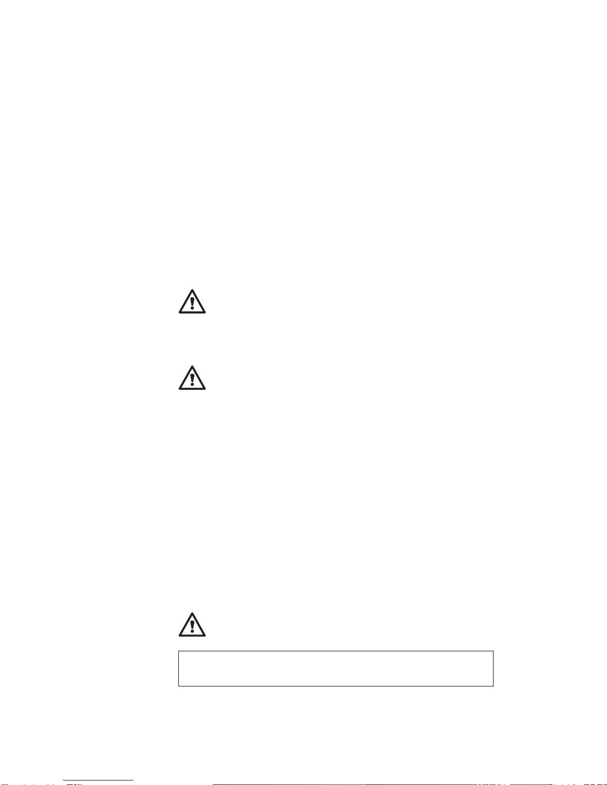
DANGER:
The power cord must be used with a properly grounded outlet.
Electrical current from power, telephone, and communication
cable is hazardous. To avoid shock hazard, connect and
disconnect cables as shown below when installing, moving, or
opening the covers of this product or attached the devices.
Turn everything OFF.
Turn everything OFF.
First, attach all cables to devices. First, remove the power cord from
the outlet.
Attach the signal cables to
receptacles.
Remove signal cables from
receptacles.
Attach the power cord to an outlet.
Remove all cables from devices.
Turn the device ON.
Note: In the U.K., by law, the
telephone line cable must be
connected after the power cord.
Note: In the U.K., by law, the
power cord must be disconnected
after the telephone line cable.
To Connect To Disconnect
viii IBM ThinkPad SelectaDock II User's Guide

About This Book
This book contains information you need when you use the IBM
ThinkPad SelectaDock II docking station. It is organized into the
following chapters and appendixes:
Chapter 1, “Introduction,” introduces the features of the
SelectaDock II docking station.
Chapter 2, “Using the SelectaDock System,” provides the
procedures for setting up the SelectaDock II docking station,
modes of operation, configuration information, and information
about docking and undocking the computer to SelectaDock
system.
Chapter 3, “Installing and Removing Options,” describes how
to install and remove options.
Chapter 4, “Using the Security Features,” describes how you
can protect the SelectaDock system against unauthorized use and
theft.
Chapter 5, “Setting Up for Sharing a SelectaDock System,”
describes how to set up a system for multiple users to share the
SelectaDock system.
Chapter 6, “Using the SCSI Controller,” provides information
about configuring for and using the SCSI controller.
Chapter 7, “Solving Problems,” describes how you can isolate
and resolve SelectaDock II problems.
Appendix A, “Tips, Hints, and Limitations,” provides tips, hints,
and limitations that help you use a computer in the SelectaDock II
environment.
Appendix B, “Using the SCSI Support Software,” provides
information about the installation and use of the SCSI device
drivers and the SCSI diagnostics utility program.
Appendix C, “Specifications,” provides the specifications
associated with the SelectaDock II docking station, as well as the
power cords part numbers.
Appendix D, “Product Warranty, Notices, and Statements,”
contains the warranty statement for the SelectaDock II docking
station, notices, trademarks, the FCC statement, the CDCC
statement, and the EC directive conformance statement.
Copyright IBM Corp. 1996 ix

xIBM ThinkPad SelectaDock II User's Guide

Chapter 1. Introduction
This chapter contains:
Standard Features . . . . . . . . . . . . . . . . . . . . . . . . . . . . 4
Unpacking the Box ............................ 5
Locating the Features .......................... 6
Front View . . . . . . . . . . . . . . . . . . . . . . . . . . . . . . . 6
Side View . . . . . . . . . . . . . . . . . . . . . . . . . . . . . . . . 8
Rear View (Rear and Connector Covers Removed) ....... 9
Inner View . . . . . . . . . . . . . . . . . . . . . . . . . . . . . . 10
SelectaDock II Status Indicators ................... 11
The IBM ThinkPad SelectaDock II docking station works with the IBM
ThinkPad SelectaDock Base Model I to provide a complete docking
system for IBM ThinkPad 760E series computers.
Important
1. The SelectaDock II docking station supports only PCI bus
computers. It does not support ISA bus computers, even
though the SelectaDock Base Model I supports both PCI and
ISA bus computers. If you try to dock an unsupported
computer to the SelectaDock system, you will be alerted by the
Attention indicator and a series of beeps. If you try to hot- or
warm-dock an unsupported computer to the SelectaDock
system, the system will shut down automatically.
2. Make sure that you are using the latest system ROM version
in the ThinkPad system. See “Setting Up Your ThinkPad
System” on page 14.
Copyright IBM Corp. 1996 1

You need each of the following:
ThinkPad 760E series computer (hereafter called the
computer
1)
SelectaDock Base Model I (hereafter called the
SelectaDock base
2)
SelectaDock II docking station (hereafter called the
docking station
3)
SelectaDock Docking System (hereafter called the
SelectaDock
system
4), consisting of the SelectaDock base plus the docking
station.
The
SelectaDock system
4 represents a single stationary unit to
which your computer is attached. In this guide, attaching or detaching
your computer to or from the SelectaDock system is called
docking
or
undocking
. You dock or undock your computer to the SelectaDock
system.
By installing the SelectaDock system, you greatly increase the
expandability of your computer.
The SelectaDock system's easy-to-use design also enables you to
dock or undock while the computer is powered on (hot docking and
undocking) with operating system support.
2IBM ThinkPad SelectaDock II User's Guide

Another highlight of the SelectaDock system is its strong security
features that protect every removable device in the system, including
the SelectaDock system itself, from theft. You can also use a hard
disk password on the drive installed in the docking station.
The docking station is also equipped with the UltraBay. You can
easily install an UltraBay-compatible CD-ROM drive, a diskette drive,
or up to two hard disk drives into the UltraBay.
Chapter 1. Introduction 3

Standard Features
The following table summarizes the standard features of the
SelectaDock system:.
Audio features Audio line-out jack
Speaker-in jack
Headphone jack
Stereo speakers
Security features Security key lock
PCMCIA card (PC Card) lock
MicroSaver lock (with the SelectaDock Base Model I)
Multiuser support security
Cable management
features With the SelectaDock Base Model I:
A mouse/pointing device connector
A keyboard/numeric keypad connector
An external diskette drive connector
A parallel connector
A serial connector
An external monitor connector
Desktop-equivalent
features A MIDI/joystick port (sometimes called a game port)
Two full-size PCI/ISA adapter card shared slots
One half-size PCI slot
An UltraBay tray or a 1-inch-high bay
A half-height bay
An external SCSI-2 device connector
Two PCMCIA slots
4IBM ThinkPad SelectaDock II User's Guide
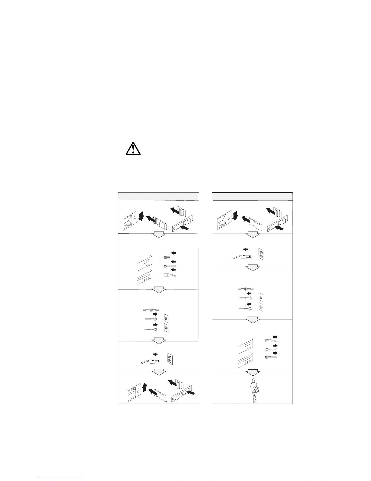
Unpacking the Box
When you unpack your docking station, check to be sure that you
have the following items. If any item is missing or damaged, call IBM
or your point of purchase.
SelectaDock II User's guide
5 diskettes Power cord
UltraBay bezel for diskette drive UltraBay bezel for CD-ROM drive
1-inch bay tray 1-inch-high blank bezel
Chapter 1. Introduction 5

Locating the Features
This section identifies the features for the docking station. Symbols
for connectors are printed near each connector for easy identification.
Front View
1The multiuser lock enables multiple users
to share the SelectaDock system while
maintaining security. For more information,
see “Setup Procedure” on page 75.
2The PC Card lock protects PC Cards from
being removed. For more information, see
“Installing or Removing a PC Card” on
page 59.
3You can slide the SelectaDock base lock
to hold the SelectaDock base in position. For
more information, see “Attaching or Removing
the SelectaDock Base to or from the Docking
Station” on page 18.
4The half-height drive space
accommodates drives such as an IDE drive or
a SCSI drive. For more information, see
“Installing or Removing a Drive in the
Half-Height Drive Space” on page 49.
5The half-height drive space blank bezel
covers the front part of the drive space. It is
attached to your docking station when it is
shipped.
6The status indicators indicate the current
status of the docking station. For more
information, see “SelectaDock II Status
Indicators” on page 11.
6IBM ThinkPad SelectaDock II User's Guide

7The UltraBay eject hole is where you put
your fingers in to pull out the UltraBay tray.
For more information, see “Installing or
Removing a Drive in the UltraBay Tray” on
page 35.
8The UltraBay blank bezel is removed
when a CD-ROM or diskette drive is installed
in the UltraBay. It is attached to your docking
station when it is shipped. For more
information, see “Installing or Removing a
Drive in the UltraBay Tray” on page 35.
9The attaching guides are where the
SelectaDock base slits are inserted for
attaching. For more information, see
“Attaching or Removing the SelectaDock Base
to or from the Docking Station” on page 18.
1The UltraBay tray is the tray on which
the UltraBay devices are attached. For more
information, see “Installing or Removing a
Drive in the UltraBay Tray” on page 35.
11 The UltraBay connector connects a
CD-ROM drive or a diskette drive. For more
information, see “Installing or Removing a
Drive in the UltraBay Tray” on page 35.
12 The UltraBay front HDD connector
connects a hard disk drive. It is located in the
front part of the UltraBay. For more
information, see “Installing or Removing a
Drive in the UltraBay Tray” on page 35.
13 The UltraBay back HDD connector
connects a hard disk drive. It is located in the
back part of the UltraBay. For more
information, see “Installing or Removing a
Drive in the UltraBay Tray” on page 35.
14 The UltraBay lock holds the UltraBay
tray to the docking station For more
information, see “Installing or Removing a
Drive in the 1-Inch-High Drive Space” on
page 44.
15 The MicroSaver lock hole is where you
can set the MicroSaver lock. For more
information, see “Securing the SelectaDock
Docking System with the MicroSaver Lock” on
page 72.
16 The feature jumpers enable or disable
the joystick feature by jumper blocks. For
more information, see “Using the MIDI/Joystick
Port” on page 61.
17 The SelectaDock base connector is a
system interface that connects the
SelectaDock base. For more information, see
“Attaching or Removing the SelectaDock Base
to or from the Docking Station” on page 18.
Chapter 1. Introduction 7
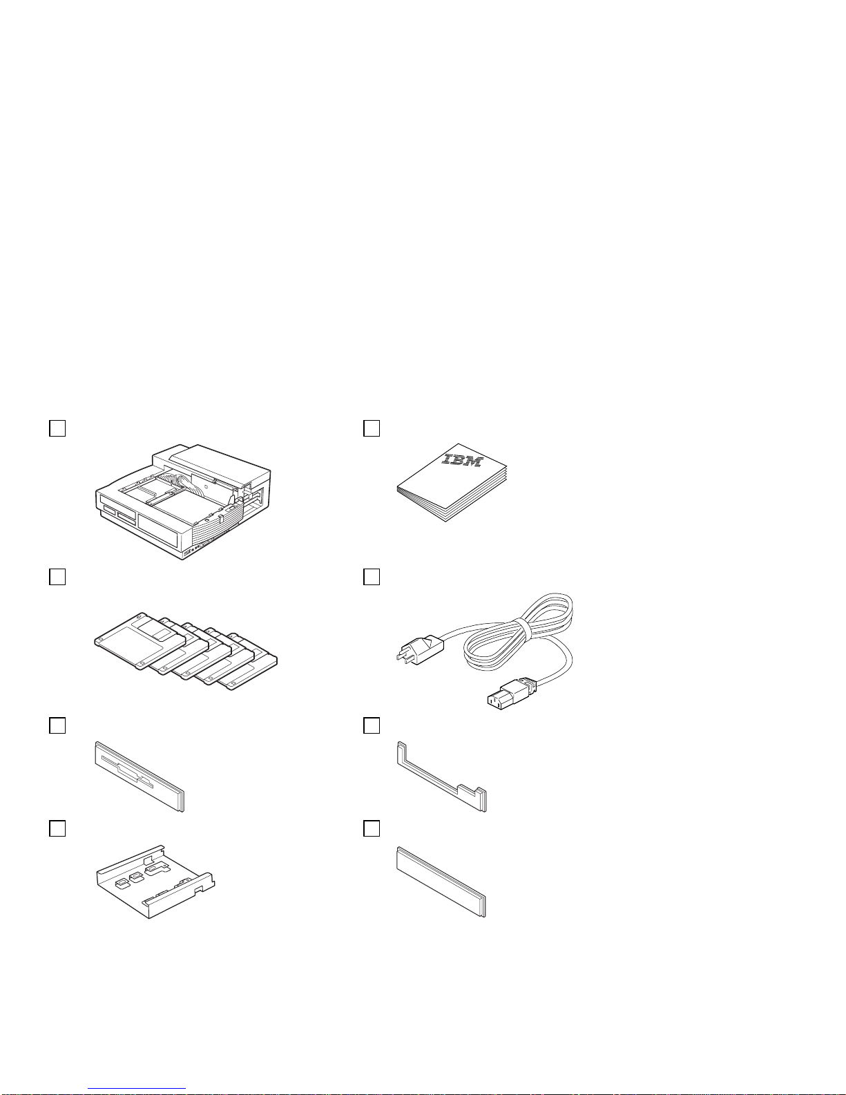
Side View
1The volume knob is where you can adjust
the volume of the stereo sound.
2The headphone jack is where you can
plug in a headphone.
3The line-out jack provides audio stereo
output, and is where an external audio
equipment line-in can be plugged.
4The speaker-in jack* provides audio stereo
input, and is where an external audio
equipment line-out can be plugged. This
signal is mixed internally with UltraBay
CD-ROM audio and with the audio sent from
your computer.
5The MIDI/joystick port is where you
connect the MIDI/joystick cable. For more
information, see “Using the MIDI/Joystick Port”
on page 61.
6The PCMCIA slots are where you can
insert 68-pin, credit-card-size PC Cards of the
same specifications as the computer's
PCMCIA slots. For more information, see
“Installing or Removing a PC Card” on
page 59.
7The SCSI connector connects a SCSI
(Small Computer System Interface)-2 drive
cable. For more information, see “Connecting
External SCSI Devices” on page 63.
*This speaker-in jack is for the speakers in the SelectaDock system, not for the speakers in your computer.
8IBM ThinkPad SelectaDock II User's Guide
Other manuals for SelectaDock II
1
This manual suits for next models
1
Table of contents
Other IBM Laptop Accessories manuals


