IBSG D-31M User manual

IBSG Co., Ltd., 26 Polytechnicheskaya str., St-Petersburg, 194021 RUSSIA, [email protected], www.ibsg-st-petersburg.com
The universal driver
for LEDs
D-31M
Operations manual
SUNSTAR传感与控制 http://www.sensor-ic.com/ TEL:0755-83376549 FAX:0755-83376182 E-MAIL:[email protected]
SUNSTAR自动化 http://www.sensor-ic.com/ TEL: 0755-83376489 FAX:0755-83376182 E-MAIL:[email protected]

- 2 -
Contents
1. Application 3
2. Features 3
3. Service conditions 4
4. Appearance of the driver and its interface 5
5. Mode description 7
5.1 Quasi continuous wave 7
5.2 Pulsed mode 7
6. Operating instruction 9
7. Technical characteristics 12
8. Block diagram 13
SUNSTAR传感与控制 http://www.sensor-ic.com/ TEL:0755-83376549 FAX:0755-83376182 E-MAIL:[email protected]
SUNSTAR自动化 http://www.sensor-ic.com/ TEL: 0755-83376489 FAX:0755-83376182 E-MAIL:[email protected]

- 3 -
1. Application.
The driver D-31M is designed for power supply of Mid-IR LEDs
manufactured by IBSG.
2. Features.
•The driver D-31M provides two modes of operation: Quasi Continuous
Wave mode (the mode of maximum average optical power from the
LED) and pulse mode (the mode of maximum peak optical power from
the LED).
•The possibility to tune the LED current amplitude, repetition rate and
pulse duration, to select the optimal mode of the LED.
•The synchronization capability with a selective amplifier or with some
other device.
•Easy and durable in use.
WARNING!
Please, do not use multimeter to control the adjust current!
Please, contact your provider regarding these questions.
SUNSTAR传感与控制 http://www.sensor-ic.com/ TEL:0755-83376549 FAX:0755-83376182 E-MAIL:[email protected]
SUNSTAR自动化 http://www.sensor-ic.com/ TEL: 0755-83376489 FAX:0755-83376182 E-MAIL:[email protected]

- 4 -
3. Service conditions.
Temperature tolerance -15 °С..+50 °С
Relative air humidity (at temperature + 35°С) less then 80 %
Atmospheric pressure 86..107 kPa
SUNSTAR传感与控制 http://www.sensor-ic.com/ TEL:0755-83376549 FAX:0755-83376182 E-MAIL:[email protected]
SUNSTAR自动化 http://www.sensor-ic.com/ TEL: 0755-83376489 FAX:0755-83376182 E-MAIL:[email protected]

- 5 -
4. Appearance of the driver and its interface.
Fig.1.Appearance of the driver and its interface.
SUNSTAR传感与控制 http://www.sensor-ic.com/ TEL:0755-83376549 FAX:0755-83376182 E-MAIL:[email protected]
SUNSTAR自动化 http://www.sensor-ic.com/ TEL: 0755-83376489 FAX:0755-83376182 E-MAIL:[email protected]

- 6 -
1. The jack for the LED connection.
2. Lookup table of switch position and pulse duration. (The table for switch
position correlation with pulse duration)
3. The multiposition switch for adjusting the pulse duration.
4. The indicators of selected frequency.
5. The button of frequency selection.
6. The jack for the cable of AC/DC adapter.
7. The jack for synchronization cable.
8. The button of mode selection.
9. The start/stop button of LED power supply.
10.The LED current indicator.
11.The red LED indicator of failure of LED current.
12.The multiposition switch for adjusting the LED current.
13.The green LED indicator of quasi continuous wave mode.
14.The green LED indicator of pulse mode.
15.Lookup table of switch position and LED current amplitude. (The table for
switch position correlation with LED current amplitude)
SUNSTAR传感与控制 http://www.sensor-ic.com/ TEL:0755-83376549 FAX:0755-83376182 E-MAIL:[email protected]
SUNSTAR自动化 http://www.sensor-ic.com/ TEL: 0755-83376489 FAX:0755-83376182 E-MAIL:[email protected]

- 7 -
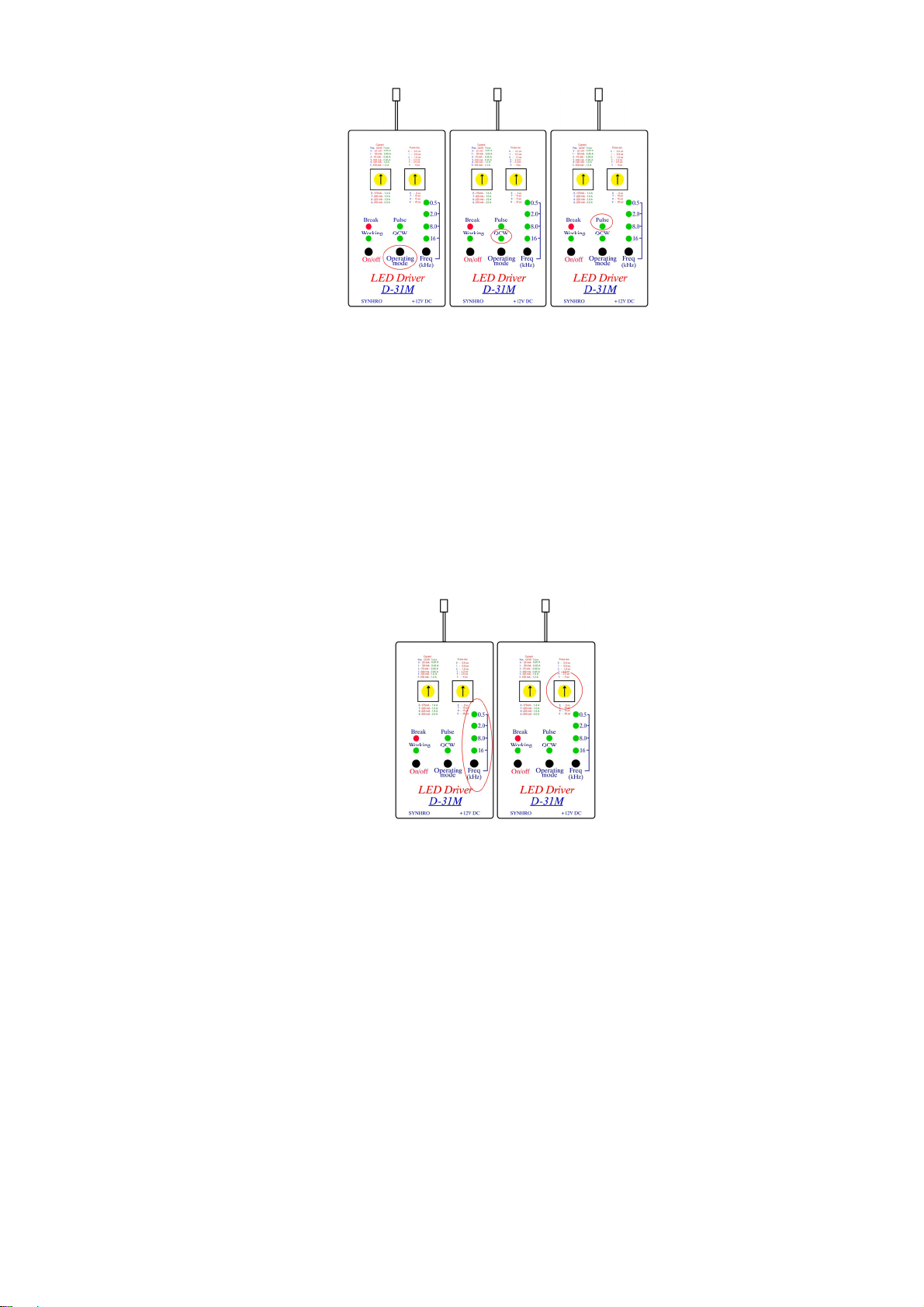
5. Mode description.
Driver provides two modes of operation: Quasi Continuous Wave (quasi
steady-state) mode and Pulse mode.
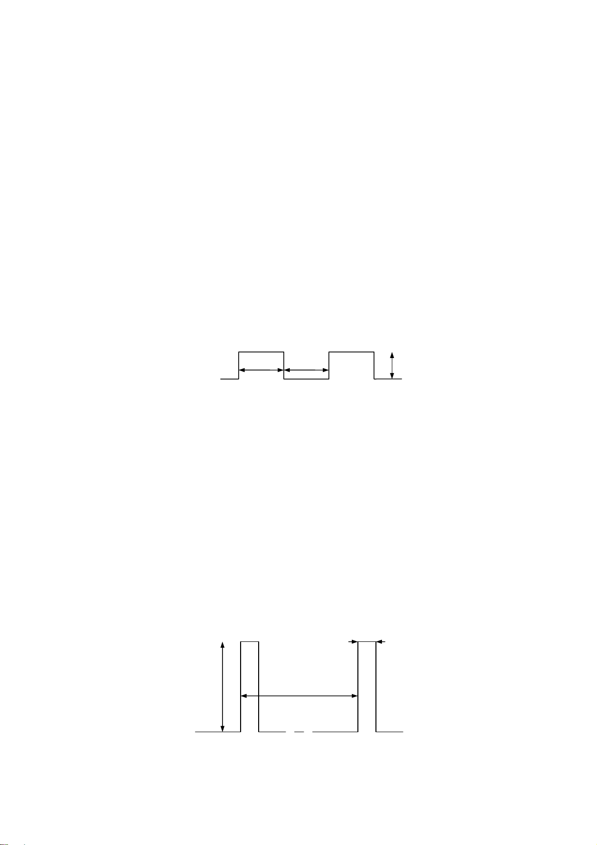
5.1. Quasi continuous wave mode – the oscillating mode of symmetrical unipolar
meander (fig.2.). Such mode provides maximum average optical power from the
LED. The Led current in this mode can be changed in the range from 20 to 250
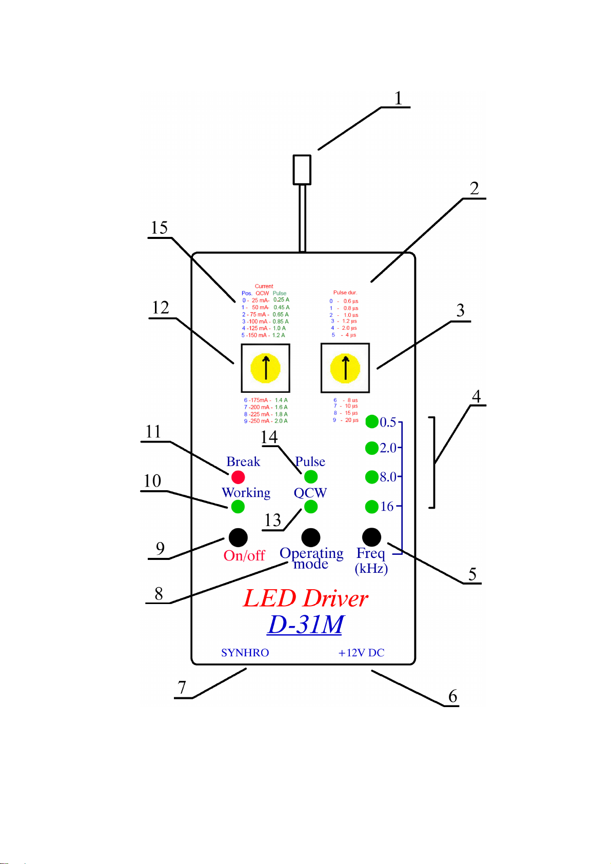
mA by using the multiposition switch for adjusting the LED current (12). Using
the button 5 one of four frequencies (512 Hz, 2 kHz, 8 kHz and 16 kHz) can be
selected. The pulse duration will be respectively equal 1000 µs, 250 µs, 62 µs and
31 µs.
Fig.2. Current-time relation in case of continuous wave mode.
5.2. Pulse mode – the oscillating mode of pulse sequence (fig.3). Such mode
provides maximum peak optical power from the LED. Similarly to the quasi
continuous wave mode, by adjusting the switch 12 the LED current can be
changed, but in the wider range: from 0,1 to 2,0 A. Using the button 5 one of the
four frequencies (512 Hz, 2 kHz, 8 kHz and 16 kHz) can be selected. Pulse
duration can be also selected in the range from 0.6 to 20 µs with the help of switch
3.
Fig.2. Current-time relation in case of pulse mode.
0,6 -20 µs
62-2000 µs
f=0,5-16 kHz
31-1000 µs 31-1000 µs
20-250 mА
f=0,5-16 kHz
0-2 А
SUNSTAR传感与控制 http://www.sensor-ic.com/ TEL:0755-83376549 FAX:0755-83376182 E-MAIL:[email protected]
SUNSTAR自动化 http://www.sensor-ic.com/ TEL: 0755-83376489 FAX:0755-83376182 E-MAIL:[email protected]

- 8 -
Note! Please, don’t use the combination of frequency and pulse duration that gives
a duty cycle more than 10 percents (table 1).
Note! We recommend to use the pulse current amount to 2 A only at pulse
duration less than 1 µs. Otherwise used LED can be broken.
Frequency
512 Hz 2 kHz 8 kHz 16 kHz
0,6
0,8
1
1,2
2
4
8
10
15
Pulse duration, µs
20
Table 1. Permissible and impermissible combinations
of frequency and pulse duration in pulse mode.
SUNSTAR传感与控制 http://www.sensor-ic.com/ TEL:0755-83376549 FAX:0755-83376182 E-MAIL:[email protected]
SUNSTAR自动化 http://www.sensor-ic.com/ TEL: 0755-83376489 FAX:0755-83376182 E-MAIL:[email protected]

- 9 -
6. Operating instruction.
1. Carefully combine the wires of the LED with pins of connector “LED” (1)
tightly till fixation.
Note! Marked with the red point pin of connector “LED” must be connected with
the appropriate wire of the LED (It’s marked with the red point too). In the case of
wrong junction the LED can be damaged.
Fig.4. Observance of polarity during the connection
between the LED and the LED connector (1).
Note! LED case must be electrically isolated from the ground.
2. If necessary with the help of cable for synchronization connect the signal
detector with the driver D-31M (jack “SYNCRO” (7)).
Fig.5. The polarity of jackplug of cable for synchronization.
3. Insert the jackplug of cable of AC/DC adapter into connector "+12V DC" (6).
Fig.6. The polarity of jackplug of power cable.
4. Using the button “Operation mode” (8) select the operating mode of the driver:
QCW or pulse. The appropriate green LED indicator “Pulse” (14) or “QCW” (13)
will be turned on.
SUNSTAR传感与控制 http://www.sensor-ic.com/ TEL:0755-83376549 FAX:0755-83376182 E-MAIL:[email protected]
SUNSTAR自动化 http://www.sensor-ic.com/ TEL: 0755-83376489 FAX:0755-83376182 E-MAIL:[email protected]

- 10 -
аb c
Fig.7. a – the button of mode selection, b – QCW mode, с– pulse mode.
5. Set the switch “Current” (12) to the position “0”, corresponding the
minimum value of LED current.
6. Using the button “Freq” (5) select one of four values of frequency. In the case of
working in the pulse mode select the requisite value of pulse duration by adjusting
the switch “Pulse dur.” (3) and using the table 2 on the driver case.
аb
Fig.8. a – the button of frequency selection and the indicators of selected frequency,
b – multiposition switch for adjusting the pulse duration.
7. Switch on the LED current by depress the button “On/Off” (9). The green LED
indicator “Working” (10) will be turned on. In the event that the red LED indicator
“Break” (11) go on working that will be mean the failure of LED current (That is
the LED is damaged). After that, set the LED current using the switch 12 and table
15.
SUNSTAR传感与控制 http://www.sensor-ic.com/ TEL:0755-83376549 FAX:0755-83376182 E-MAIL:[email protected]
SUNSTAR自动化 http://www.sensor-ic.com/ TEL: 0755-83376489 FAX:0755-83376182 E-MAIL:[email protected]

- 11 -
аb с
Fig.9. a – the LED current is off, b – the Led current is on,
с– the LED current is on, but the LED circuit is broken .
8. Please, ascertain that the running LED current complies with the LED
specification.
SUNSTAR传感与控制 http://www.sensor-ic.com/ TEL:0755-83376549 FAX:0755-83376182 E-MAIL:[email protected]
SUNSTAR自动化 http://www.sensor-ic.com/ TEL: 0755-83376489 FAX:0755-83376182 E-MAIL:[email protected]

- 12 -
7. Technical characteristics.
Input voltage +12 V, stabilized
Voltage tolerance -5..+5 %
Power consumption Less then 4 W
Adjustment temperature range -10 °С..+25 °С
Board dimensions 90×50×25 mm
Weight 90 g
QCW mode Pulsed mode
Pulse duration 31 – 1000 µs 0,6 – 20 µs
Repetition rate (Frequency) 0,5 – 16 kHz 0,5 – 16 kHz
Output current amplitude 20 – 250 mA 0,1- 2,0 A
SUNSTAR传感与控制 http://www.sensor-ic.com/ TEL:0755-83376549 FAX:0755-83376182 E-MAIL:[email protected]
SUNSTAR自动化 http://www.sensor-ic.com/ TEL: 0755-83376489 FAX:0755-83376182 E-MAIL:[email protected]

- 13 -
8. Block diagram
The driver block diagramme (pulse power supply) D-31M is presented in
fig.10.
The pulse power supply of light-emitting diodes functionally consists of
generator G, single-shot multivibrator M, multiplexer MX1, voltage-to-current
converterv U/I, the pulse power supply converter DC/DCLED.
The generator G forms the pulse sequence with variable repetition rate. The
repetition rate can be changed with the help of the button "Frequency". It's
indicated by light-emitting diodes “2 kHz”, “4 kHz”, “8 kHz”, “16kHz”. The
waiting multivibrator M and the multiplexer MX1 receive the voltage impulses in
the form of a meander from generator G .
The single-shot multivibrator M generates voltage impulses with the
adjustable fixed duration synchronously with rise-up portion of input voltage
impulses. Switching of duration of impulses is carried out by means of switch SW1
in the range from 0,6 to 20 µс.
The multiplexer MX1 by means of the button “Operating mode” switch the
clock pulses on the input of voltage-to-current converter U/I. In addition clock
pulses come to the jack “Synchro” for synchronisation with the external
photoreception amplifier.
The IR-light-emitting diode LED recive a pulse current from U/I converter.
Start-up of circuit U/I is carried out by means of the button “Curent ON/OFF”. The
green light-emitting diode “Work” lights up in that case . If the circuit of the LED
is broken the light-emitting diode “Break” lights up. Adjustment of the amplitude
of the LED pulse current is implemented by means of a multiposition switch SW2.
The DC / DC circuit is a pulse voltage converter from + 12 V in + 5 V, -5 V
for power supply of all the elements of the D-31M. The input voltage of DC / DC
converter supplies from “+12 VDC” jack.
SUNSTAR传感与控制 http://www.sensor-ic.com/ TEL:0755-83376549 FAX:0755-83376182 E-MAIL:[email protected]
SUNSTAR自动化 http://www.sensor-ic.com/ TEL: 0755-83376489 FAX:0755-83376182 E-MAIL:[email protected]

- 14 -
Frequensy
0,5 2 4 8 kHz
D
C/
D
C
+12В
Pulse duration
Working/Break
Voltage-to-current
converterv U/I
Pulse/QCW
Frequensy
Pulse
generator
0,5 2 4 8 kHz
Current
D
C/
D
C
+12В
+12V
GND
+5V
-5V
Synchronisation
LED
Multiplexer
МХ1
Single-shot
multivibrator
M
Sw1 Sw2
Fig.10. The Block diagram of D-31M.
DC/DC
+12 V
DC/DC
SUNSTAR传感与控制 http://www.sensor-ic.com/ TEL:0755-83376549 FAX:0755-83376182 E-MAIL:[email protected]
SUNSTAR自动化 http://www.sensor-ic.com/ TEL: 0755-83376489 FAX:0755-83376182 E-MAIL:[email protected]
Table of contents