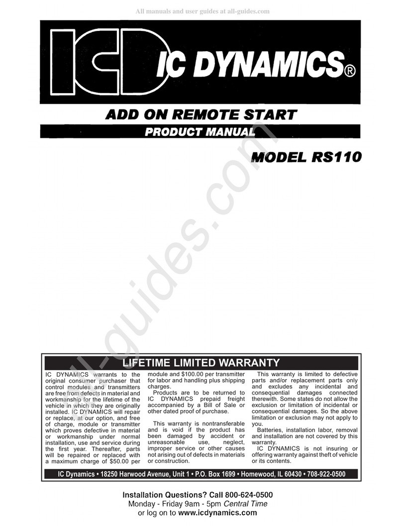
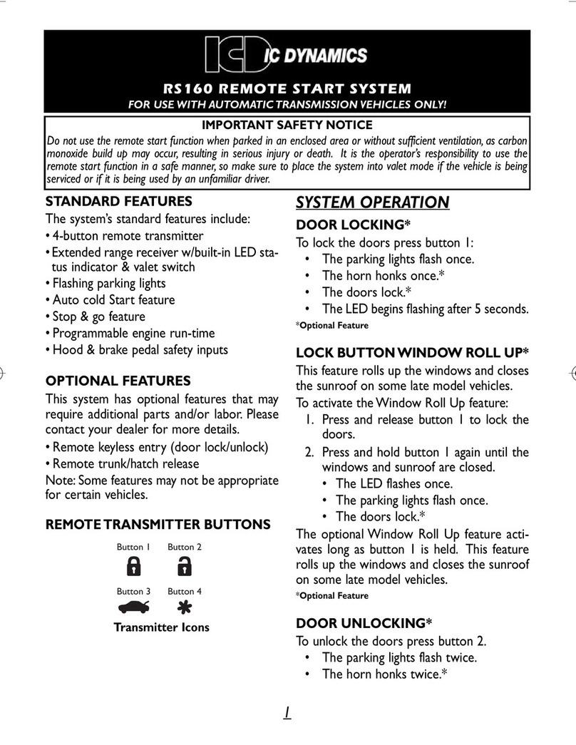
IC Dynamics RS125 User manual

IC DYNAMICS
RS125
122706
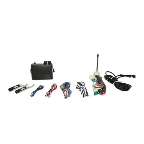
PARTS LIST
WARNING
Remote start module
Four button transmitter
Ten wire harness
Six wires for power and ignition hook up
Three wire harness for optional door lock/unlock
Three wire harness for optional power trunk release/
factory alarm disarm/vacuum switch
LED
Service/program switch
Pin switch
Bullet connector for pin switch
Antenna
Antenna double faced mounting tape
Antenna extension harness
Installation instructions
Operating instructions
This Remote Car Starter is for vehicles with automatic trans-
missions and fuel injected gasoline or diesel engines only.
DO NOT install this Remote Car Starter in a standard stick
(manual transmission) or a vehicle that has a carburetor.
Serious personal injury or property damage could occur.
Never use the Remote Start on a vehicle that is in a garage
with the doors closed, an enclosed building, etc. Proper ven-
tilation is required to avoid serious personal injury.
Installation must be done by a qualified mechanic. We rec-
ommend that all connections be soldered.
•
•
•
•
•
•
•
•
•
•
•
•
•
•
•
18
9am.– 5pm.
Central time
Monday – Friday
Log on anytime to
www.icdynamics.com
or Call 800-624-0500
Installation Questions?
REMOTE CONTROL CAR STARTER
INSTALLATION INSTRUCTIONS
Model RS125
IC DYNAMICS
®
With Keyless Entry and Power Trunk Release

BEFORE YOU BEGIN THE INSTALLATION:
Please read all the installation and operat-
ing instructions thoroughly. Familiarize your-
self with all the installation steps before you
do anything. Refer to the remote start vehi-
cle wiring guide. Most, but not all, vehicles
are listed in the guide. If your vehicle does
not appear, call our 800 number for specific
information on your vehicle.
Tools required for the installation: A
Philips or flathead screwdriver, wire cutters
or stripper, electrical tape, drill, soldering
iron and a multimeter or voltmeter.
Things to look for before beginning the
installation:
A) Make sure that the vehicle has an auto-
matic transmission. The remote starter will
not operate on vehicles with manual (stick
shift) transmissions.
B) Make sure it has a fuel injected gas
engine, or a diesel engine. The remote
starter will not operate on vehicles with
carborated engines.
C) See if the vehicle has an existing factory
alarm system. Many late Ford and General
Motors vehicles now include factory securi-
ty systems. The Ford system is known as
the PATS System, General Motors has the
VATS, Passlock and Passkey Systems.
Vehicles having these systems can be iden-
tified by the ignition key having a small resis-
tor pellet or ”chip“ in it, and or a security light
is present in the dash. If the vehicle has an
existing factory alarm system you must pur-
chase an optional factory alarm bypass kit
for the remote starter to operate.
1) WARNING LABEL APPLICATION
Start the installation by applying the warning
label to a highly visible location under the
hood. This warns other mechanics that the
vehicle is equipped with a remote starter,
which should be disabled before working on
the vehicle.
2) MOUNTING REMOTE STARTER MODULE
Select a suitable mounting area for the mod-
ule inside the vehicle below the dash. Do not
permanently secure the module until the
installation is complete and the operation
has been tested.
3) TEN WIRE HARNESS
White wire: Connect to the vehicle parking
light wire that switches to +12 volts when the
parking lights are turned on.
Red wire: Connect this wire (with the in line
fuse holder) to the +12 volt side of the battery.
Brown wire: Do not use this wire unless the
vehicle has an existing alarm system with a
shock sensor. If the vehicle has such an
alarm, cut the ground wire on the sensor
and connect one side to the Remote Starter
brown wire. Connect the other side to the
Remote Start Violet wire.
Black wire: Connect to a good, clean metal
ground.
Orange Wire: Do not use this wire unless
the vehicle has an existing remote control
alarm system and you are using the Remote
Starter as an add-on only. In this case, con-
nect the orange wire to the alarm’s auxiliary
channel negative output. This will allow you
to remote start the vehicle with the alarm
system’s transmitters. Note: Remote Start
range will be the same as that of the alarm
system.
Gray wire: Do not use this wire unless the
vehicle has an existing original equipment
General Motors VATS, Passlock or Passkey
system; or a Ford PATS system. These sys-
tems can be identified by the key having a
chip in it, and or red security light in the
dash. In this case connect the Gray wire to
the optional VATS by-pass Kit, or PATS by-
pass kit. These kits are not included, please
see your dealer.
Green wire: Connect the green wire to the
tach (negative) side of the coil, or wrap it
around any sparkplug wire. Do not splice or
cut the sparkplug wire. Set dip switch #1 to
the off position.
Blue wire: Connect this wire to the included
hood pin switch. The pin switch disengages
the remote starter if the hood is opened.
Insert the included bullet connector into the
pin switch to make the connection. Mount
the pin switch to a grounded metal frame or
panel. The vehicle hood must press down on
the pin switch plunger for proper operation.
Violet wire: Do not use this wire unless the
vehicle has an existing alarm system with a
shock sensor. If the vehicle has such an
alarm, cut the ground wire on the sensor
and connect one side to the Remote Starter
violet wire. Connect the other side to the
Remote Start brown wire.
REMOTE STARTER INSTALLATION INSTRUCTIONS
ENTIRE INSTRUCTIONS SHOULD BE READ BEFORE BEGINNING INSTALLATION.
122706 2
EXISTING MASTER
DOOR LOCK SWITCH
UNLOCK LOCK
87
30
87A
UNLOCK RELAY
DOOR LOCK ACTUATORS
(Solenoids or Motors)
85
86
12 Volt
Positive
Constant
Constant Ground
Constant
Ground
RELAY WIRING FOR 5 WIRE REVERSE
POLARITY MASTER DOOR LOCK SWITCH
12Volt Positive when pushing
the lock button
12Volt Positive
when pushing the
unlock button
NOTE:
Door Lock/Unlock
Relays typically mounted
under the dash near the
receiver module
Master Door Lock Switch: After
cutting the lock wire, all door locks
will be inoperable when lock button
is pressed. If only the driver’s door
lock is inoperable, the wrong wire
has been cut. Each end of the wire
must be tested with a multimeter.
Connect the end with (+)12 Volts to
87A on the relay. Connect the end
with no power to 30 on the relay.
cut and
connect to
terminals
87A and 30
x
87
30
87A
LOCK RELAY
Connect to Car 12V+Connect to Car 12V+
85
86
cut and
connect to
terminals
87A and 30
x
5RP
POSITIVE TRIGGER TRUNK RELEASE NEGATIVE TRIGGER TRUNK RELEASE
87
30
8587A
12V Positive Ground
12V Positive
Green/Black
Wire of 3 pin
red connector
Positive trunk wire Negative trunk wire
86
87
30
8587A Green/Black
Wire of 3 pin
red connector
86
PROCEDURE FOR INSTALLATION OF TRUNK/HATCH RELEASE
NOTE:
The wires can usually be found at the trunk release switch
NOTE:
DO NOT remove or change
any factory relays already in place.
7
WIRING INSTRUCTIONS
3P (
3 wire positive system
) There are 3 wires com-
ing from the switch. The switch has no power at
rest, receives +12 volt power when in use.
(
See figure 3P
)
5RP (
5 wire reverse polarity system
)
There are usually 5 wires coming from the switch.
The switch is grounded at rest, receives +12 volt
power when in use. (
See figure 5RP
)
After determining type switch and identifying
switch wires, you must test each switch wire
for polarity (+ or –) using a test meter. After
confirming polarity for each wire, proceed to
connect wires in accordance with the appropriate
wiring diagram, 3P or 3N or 5RP.
BLUE WIRE
of 3 pin white
connector
GREEN WIRE
of 3 pin white
connector
VEHICLE
BATTERY
(+)12 volt power
30 AMP FUSE
+
VEHICLE
BATTERY
(+)12 volt power
30 AMP FUSE
+
Service/Program
Switch
BROWN IGNITION
#2 OUTPUT
ACCESSORIES, HEATER,
AIR CONDITIONER 12V (+)
STARTER (+)
VIOLET
ORANGE
RED
RED
YELLOW IGNITION #1 OUTPUT
Remote
Start
Receiver
Module
TEN PIN CONNECTOR
BROWN
RED
WIRING DIAGRAM
GRAY (–) grounded output
For OE security system
For spark plug wire
or tach sensing
(–) output
for sensor trigger wire.
(–) output to alarm
sensor output wire.
ORANGE
GREEN
RED
BLUE
WHITE
To door lock (–) pulse
(Optional relay’s may be required. Not included.)
See Relay Installation Sheet
Do not use
LED
To door unlock (–) pulse
(Optional relay’s may be required. Not included.)
See Relay Installation Sheet
White
Jack
Antenna
Jack
Red
Jack
Red
Jack
Blue
Jack
BRAKE
PEDAL
GREEN
BLUE
VIOLET
YELLOW
GREEN/BLACK
RED
YELLOW
To power trunk release
(Optional relay may be required. Not included.)
See Relay Installation Sheet
Factory alarm disarm
(Optional relay required. Not included.)
See Relay Installation Sheet
For optional vacuum switch sensing
(Optional vacuum switch may be required. Not included.)
SENSOR
VEHICLE
BATTERY
(Optional, See Installation Instructions)
(–) input from alarm 2nd channel
(Optional, See Installation Instructions)
(+) trigger input From
brake light switch wire
(+)12 volt
power
(–) trigger input
From hood pin switch,
(–) TO GROUND
(+) 12 Volts when brake pedal depressed
BLACK
(Optional, See Installation Instructions)
Two pin blue connector: This is for the
service/program switch. Mount this switch
near the drivers side and in a hidden loca-
tion under the dash. It should be accessi-
ble for use.
6) REMOTE PROGRAMMABLE FEATURES:
The remote starter has four programmable
features:
#1 - 2nd ignition relay on/off
On = used for 2nd ignition output.
Off = used for 2nd accessory output
#2 - Engine run time
On = 12 minutes
Off = 24 minutes
#3 - Door lock pulse time
On = .75 seconds
Off = 3 seconds
#4 - Double unlock pulse
On = single unlock pulse
Off = double unlock pulse
How to enter into the program mode:
1) Turn the ignition key to the on position.
2) Within ten seconds press the
service/program switch five times. The
parking lights and the dash mount LED will
flash three times.The system is now in pro-
gram mode.
How to program a feature:
1) Press the service/program switch the
same number of times as the feature num-
ber above. Once is for feature #1 2nd igni-
tion relay on/off, twice is for #2 engine run
time, etc. The parking lights and dash
mount LED will flash each time the switch
is pushed to confirm.
2) Press button #1 on one of the remote
transmitters to turn the feature to the ”on”
position. The parking lights and dash
mount LED will flash one time to confirm.
3) Press button #2 on one of the remote
transmitters to turn the feature to the ”off“
position. The parking lights and dash
mount LED will flash twice to confirm.
4) The system will automatically exit from
the program mode.
7) DIP SWITCHES:
There are four individual dip switches,
each controlling a specific function. The
switch should be left in the “on” position if
it is not being used. To use the function,
put the dip switch in the “off” position
#1:
Is used for the tach or sparkplug wire
sensing hook up. Put this switch in the “off”
position.
#2: Is used for the optional vacuum switch.
Put this switch in the “off” position if you are
using the optional vacuum switch.
#3: Is used to increase the starter crank
time. To increase the crank time put the
switch in the “off” position.
#4: Is used if the vehicle has a diesel
engine. If the vehicle has a diesel engine,
put this switch in the “off” position.
ON
OFF
1234
INSTALLATION INSTRUCTIONS CONTINUED
ENTIRE INSTRUCTIONS SHOULD BE READ BEFORE BEGINNING INSTALLATION.
DIP
SWITCHES
Remove cover
to set.
See installation
instructions.
HOOD PIN SWITCH
30 AMP FUSE
ALARM
SYSTEM
122706
+
(+) output To parking light wire
that supplies (+) 12 volt power
4 5
POSSIBLE REMEDY
Check power and
ground connection.
Try to reprogram
remote back into
module.
Check connection
to starter wire.
Check tach wire
connection.
Check for factory
security system
Check for 2nd
ignition
Check to see if unit is
in service mode
Check to see if unit is
in auto cold start
mode
Check to see if switch
#3 is in
off position
TROUBLE SHOOTING
PROBLEM
Unit will not
respond to
remotes
Vehicle will not
crank
Vehicle starts,
then shuts down
Vehicle starts
but check engine
light comes on
Keyless entry
works but will
not remote start.
LED light solid red.
Vehicle is starting
on its own.
Vehicle will not
stay running,
needs longer
crank time.
ON DIP

6
3N
GREEN WIRE of 3
pin white connector
UNLOCK LOCK
Constant
Ground
WIRING FOR 3 WIRE NEGATIVE TRIGGER
MASTER DOOR LOCK SWITCH NO
RELAYS
REQUIRED
Negative
when pushing the
unlock button Tap
into this wire with
Green wire of 3 pin
white connector
Negative
when pushing the
lock button
Tap into
this wire with Blue
wire of 3 pin white
connector
BLUE WIRE of 3 pin
white connector
EXISTING MASTER
DOOR LOCK SWITCH
Yellow wire: Connect this wire to a brake
switch wire that provides +12 volts when
the brake pedal is pressed. This is a safety
feature that disengages the Remote
Starter when the brake pedal is pressed.
4) SIX SEPARATE POWER AND IGNITION
WIRES:
These connections will be made
with wires found in the vehicle’s ignition
switch wiring harness.
Red wire #1: This is the systems main
power wire. Connect this wire (with the in
line fuse holder) to the +12 volt side of the
battery.
Red wire #2: This is the auxiliary power
input. Connect this wire (with the in line
fuse holder) to the +12 volt side of the bat-
tery.
Brown wire: This is the auxiliary ignition or
accessory wire. Do not use this wire unless
the vehicle has a second ignition or acces-
sory wire. Many late model vehicles have a
second (or more) ignition or heater,
defroster, air conditioner, etc. wire. If that is
the case, connect the brown wire to the
wire in the ignition switch wire harness that
switches to +12 volts when the car is being
started and does not shut off.
Yellow wire: This is the main ignition wire.
Connect this wire to the vehicle ignition
switch wire. This wire measures +12 volts
when the ignition is in the run and start
positions. This wire provides current to the
vehicles coil or ignition system.
Orange wire: This is the main accessory
wire. This wire activates the vehicle heater,
defroster, or a/c when using the Remote
Starter. The blower, heater, defroster or a/c
must be left on to operate. Connect this
wire to the accessory wire that measures
+12 volts when the ignition is in the ”run”
position.
Purple wire: This is the starter wire.
Connect this wire to the vehicle starter wire
that measures +12 volts when the ignition
is in the ”crank” position.
5) PLUG IN CONNECTORS
Four pin white extended range antenna
connector: Plug the black cable into the
white four pin connector. Run the cable
under the windshield pillar and headliner.
Plug the cable into the antenna. Mount the
antenna to the windshield with the included
double sided tape.The antenna works best
mounted at the top of the windshield,
cen-
tered above or behind the rear view mirror.
Three pin white connector: Optional.
This allows you to lock/unlock the doors by
remote control. The vehicle must have
existing electric power door locks for this
feature to operate. Optional relays (not
included) may be required, see the relay
installation sheet. This harness has three
wires with a white plug. Connect the blue
wire to the (–) negative output for unlock.
Connect the green wire to the (–) negative
output for lock. Do not use the red wire.
Three pin red connector: This harness
provides optional features.You can operate
an existing power trunk release by remote
control (optional relay required, not includ-
ed), interface with a factory alarm system,
or use the vacuum switch sensing method.
This harness has three wires and a white
plug. The green/black wire is for the option-
al power trunk/hatch release. The vehicle
must have an existing power trunk or hatch
release for this feature to operate. An
optional relay is required, see the relay
installation sheet. Connect the green/black
wire to the power trunk/hatch release
switch. The red wire is used to disarm an
existing factory alarm system, allowing the
doors to be unlocked prior to remote start-
ing. This is optional, and only used if the
vehicle has an existing factory alarm.
Connect the red wire to the wire that
requires a ground pulse to disarm the fac-
tory alarm system. The yellow wire is used
for the optional vacuum switch sensing
method. If the vehicle stalls, or does not
keep running, an optional vacuum switch
(not included) must be purchased and
installed. If a vacuum switch is used, set
dip switch #2 to the off position. Install the
vacuum switch as follows:
Two pin red connector: This is for the
dash mount LED. The dash mount LED
confirms various functions. Locate a posi-
tion on the dash as high as possible for
maximum visibility. Check that you have
space in front and in back of the mounting
location. Drill a 1/4” hole, route the wires
and mount.
VACUUM
SWITCH
VACUUM TEE
Existing Car
Vacuum Hose
Existing Car
Vacuum Hose
Ground Black
from Vacuum
switch harness
122706
3
87
30
UNLOCK RELAY
85
86
EXISTING MASTER
DOOR LOCK SWITCH
UNLOCK LOCK
12 Volt Positive
Constant
RELAY WIRING FOR 3 WIRE POSITIVE
TRIGGER MASTER DOOR LOCK SWITCH
87
30
LOCK RELAY
85
86
12Volt Positive when
pushing the unlock button
Tap into this wire with
wire from terminal 30
12Volt Positive when
pushing the lock button
Tap into this wire with
wire from terminal 30
NOTE:
Door Lock/UnlocK
Relays typically mounted
under the dash near the
receiver module
Connect to Car
12 volt positive
3P
NOTE:
DO NOT remove or change
any factory relays already in place.
DOOR LOCK AND TRUNK/HATCH RELEASE
Determine the type of master door lock system your
vehicle has. This can be done by either referring to
the enclosed Remote Start Vehicle Wiring Guide or
going directly to the vehicles master door lock
switch. Since most, but not all vehicles are listed in
the guide, it may be necessary to go directly to the
switch. To do this, remove the driver’s side door
panel*. Locate the master door lock switch and
count the number of wires extending from the
switch. There are predominantly three types of
master door lock switches.
3N (
3 wire negative system
) There are 3 wires
coming from the switch. The switch has no
power at rest, grounded when in use.
(
See figure 3N
)
There are a small number of cars where the master door lock switch is located behind the passenger’s
side door panel. Typically these cars are: 93-96 Chevy Camaro, 84-96 Corvette, 92-98 Ford full size Van,
94-97 Ford Thunderbird , 94-97 Mercury Cougar and 93-96 Pontiac Firebird.
Switch wires marked with an ( ) arrow pointer require
connection to wiring harness.
BLUE WIRE
of 3 pin white
connector
GREEN WIRE
of 3 pin white
connector
Press button 4 for approximately two
seconds to activate remote start
Press button 4 for approximately two
seconds again to deactivate remote start.
REMOTE START OPERATION
Press button 1 for
approximately two
seconds to lock doors.
OPTIONAL DOOR
LOCK
OPTIONAL POWER
TRUNK/HATCH RELEASE
AUTO COLD START OPERATION
Press button 3 for approximately
two seconds to release power
trunk or hatch.
Press and hold the service program
switch and button 2 simultaneously for
five seconds to activate auto cold start.
Press and hold the service program
switch and button 2 simultaneously for
five seconds to deactivate auto cold start.
DASH MOUNT LED
Slow flash - Doors are locked (optional keyless
entry)
Rapid flash - Vehicle has been remote started
and is running.
Solid - Remote start is in the service mode.
Double flash - Auto cold start mode is activated.
PARKING LIGHTS
One flash - Doors are locked (optional keyless entry)
Two flashes - Doors are unlocked (optional keyless entry)
Four flashes - Vehicle was not started.
Five flashes - Auto cold start mode is activated.
Ten flashes - Auto cold start mode is deactivated.
IC DYNAMICS warrants to the original
consumer purchaser that control mod-
ules and transmitters are free from
defects in material and workmanship for
the lifetime of the vehicle in which they
are originally installed. IC DYNAMICS will
repair or replace, at our option, and free
of charge, module or transmitter which
proves defective in material or workman-
ship under normal installation, use and
service during the first year. Thereafter,
parts will be repaired or replaced with a
maximum charge of $50.00 per module
and $30.00 per transmitter for labor and
handling plus shipping charges.
Products are to be returned to IC
DYNAMICS prepaid freight accompanied
by a Bill of Sale or other dated proof of
purchase.
This warranty is nontransferable and is
void if the product has been damaged by
accident or unreasonable use, neglect,
improper service or other causes not
arising out of defects in materials or con-
struction.
This warranty is limited to defective
parts and/or replacement parts only and
excludes any incidental and consequen-
tial damages connected therewith. Some
states do not allow the exclusion or limi-
tation of incidental or consequential dam-
ages. So the above limitation or exclusion
may not apply to you.
Batteries, installation labor, removal
and installation are not covered by this
warranty.
IC DYNAMICS is not insuring or offer-
ing warranty against theft of vehicle or its
contents.
LIFETIME LIMITED WARRANTY
IC DYNAMICS •16072 Vandustrial Lane • P.O. Box 307 • South Holland, IL 60473 • 708-333-9060
FEATURES
Start your vehicle and turn on the heater, defroster, or air
conditioner from inside the comfort and convenience of
your home, office, etc.
Up to 500 foot range.
Four button, 3 channel remote control transmitter.
Code learning microprocessor receiver.
Parking lights activate to confirm operation and status.
Dash mount LED confirms operation and status.
Programmable engine run time, 15 or 25 minutes. Engine
automatically shuts off if the key is not inserted into the
ignition before the end of the selected run time.
Adjustable starter crank time.
Automatically makes up to three attempts to start the vehicle
each time the unit is activated.
Programmable auto cold start mode automatically starts the
vehicle and runs the engine for the selected (15 or 25 minutes)
run time every 2 hours for one 24 hour period.
Programmable auto run mode keeps the engine running while
you exit the vehicle with the key.
Keyless entry outputs for optional remote door lock/unlock.
Optional relays may be required (not included).
Power trunk/hatch release output for optional power trunk
release. Optional relay may be required (not included).
Service switch temporarily disables remote starter for attendant
parking, service, etc..
Limited lifetime warranty.
•
•
•
•
•
•
•
•
•
•
•
•
•
•
•
Press button 2 for
approximately two seconds
again to unlock doors.
OPTIONAL DOOR
UNLOCK
IC DYNAMICS
RS125
122706
REMOTE TRANSMITTER
OPERATION
Button 1 Button 2
Button 3 Button 4
REMOTE CONTROL CAR STARTER
OPERATION INSTRUCTIONS
Model RS125
IC DYNAMICS
®
With Keyless Entry and Power Trunk Release

122706
REMOTE START OPERATION
Start your car from inside your home using the remote transmitters. Ideal for
pre-warming your car on cold winter days or cooling it down during the sum-
mer. Plus, have the convenience of locking and unlocking your car and release
the power trunk/hatch with the remote transmitters. Door lock/unlock and
power trunk/hatch release are optional. Range is approximately up to 1000 feet.
BEFORE USING THE SYSTEM
Proper ventilation is required to avoid serious personal injury. Never operate
the remote starter in an enclosed garage, building, etc. Carefully read the
instructions to familiarize yourself with all the features and benefits before
attempting to operate the unit.
HOW TO REMOTE START THE VEHICLE
Press button four on either transmitter. Approximately two seconds later the
vehicle will start and the dash mount LED will flash rapidly. The remote starter
will make up to three attempts to start the vehicle each time the unit is activat-
ed.The parking lights will flash four times if the vehicle failed to start and the
doors will lock if the optional keyless entry feature is installed. Once the vehicle
is started, the heater, defroster or air conditioner will activate, provided they
were left on. The engine will run for 12 or 24 minutes, which ever it was pro-
grammed for.
HOW TO DRIVE THE VEHICLE AFTER ACTIVATING THE REMOTE
STARTER
To operate the vehicle before the normal run-time expires, simply enter the
vehicle; insert the ignition key; turn to on position and press brake pedal.
NOTE: If the brake pedal is pressed before the ignition is
turned on, the engine will turn off. Simply restart vehicle
with ignition key.
HOW TO TURN THE REMOTE STARTER OFF
If desired, the system can be turned off by pressing transmitter button four.
The remote start will disengage when one of the following occurs:
1. Fuse is removed
2. Brake pedal is depressed
3. Engine refused to start
4. Hood is opened
5. Expiration of programmed run time, 12 or 24 minutes.
AUTO COLD START
Automatic cold start, starts the vehicle and runs the engine for approximately 12 or 24
minutes every 2 hours for one 24 hour period.
To activate: press and hold the service/program switch and button 2 on the
transmitter simultaneously for 5 seconds. Parking lights will flash 5 times,
engine will start and run for 30 seconds and then shut off. This confirms the
Remote Starter is in the Auto Cold Start mode. To deactivate: press and hold the
service/program switch and button 2 on the transmitter simultaneously for 5
seconds. Parking lights will flash 10 times to confirm the Auto Cold Start is off.
Driving the vehicle and/or remote starting the vehicle during the 24 hour Auto
Cold Start period automatically deactivates the Auto Cold Start.
AUTO RUN MODE
This feature allows you to park and exit the vehicle with the key, while the engine con-
tinues to run.
To activate: 1. Press and hold the brake pedal.
2. Shift transmission into park.
3. Press button one on either transmitter.
4. The dash mount LED should be flashing rapidly.
5. Take your foot off the brake pedal, turn the ignition key
to the off position and remove.
The parking lights stay on while the vehicle is in the Auto Run mode
You may now exit the vehicle with the key while the engine is running. All the
normal safety steps are in place, the vehicle can’t be driven without the ignition
key turned to the on position, the brake pedal pressed, and the transmission put
into gear. To deactivate the Auto Run mode, follow the normal safety steps. If
the optional keyless entry feature has been installed, it can still operate while
you are out of the vehicle.
PROGRAMMABLE CODE LEARNING
Program additional transmitters with different codes to the system. The receiver micro-
processor can learn up to three different transmitter codes.
1. Turn ignition ON/OFF three times rapidly (DO NOT turn key all the
way to crank position). The third time you turn ignition on, leave key
in ON position. Dash lights will flash once.
2. Press brake pedal and hold. Dash lights will flash rapidly.
3. Press button one on remote transmitter. Dash lights will flash once.
Release brake pedal. Remote starter has now learned the new
transmitter code
NOTE: When programming additional transmitters to operate the system,
all transmitters to be used with the system must be reprogrammed at the
same time.
OPTIONAL KEYLESS ENTRY
Lock and unlock your doors with the remote transmitters.
Vehicle must have power door locks for this feature to operate. Optional relays
may be required (not included).
OPTIONAL POWER TRUNK/HATCH RELEASE
Release your power trunk/hatch with the remote transmitters.
Vehicle must have electric power trunk/hatch release for this feature to operate.
Optional relay may be required (not included).
SERVICE MODE
The service switch (usually mounted under or around the driver’s side of the dash)
allows you to temporarily disable the remote starter during service, valet parking, etc.
You can still operate the optional keyless entry (if it is installed) but the vehicle
can’t be started with the transmitters. Here is how you get into and out of the
service mode:
1. Turn the ignition key to the on position.
2. Press and hold the service switch for five seconds. The dash mount LED
will turn solid
3. Turn the ignition off.
4. Repeat steps 1-3 to get out of the service mode.
Table of contents
Other IC Dynamics Remote Starter manuals
Popular Remote Starter manuals by other brands

Code Alarm
Code Alarm Professional Series CA 5050 installation guide

Schumacher
Schumacher MityMite PS-120A owner's manual

Chamberlain
Chamberlain Series 740 user guide

Scytek electronic
Scytek electronic ASTRA 300RS product manual

Car and Driver
Car and Driver LI1006B instruction manual

Directed Electronics
Directed Electronics 440HP owner's guide