IC Dynamics RS160 User manual

1
STANDARD FEATURES
The system’s standard features include:
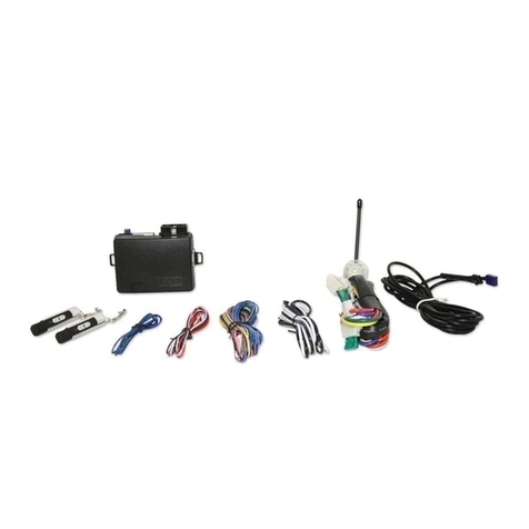
• 4-button remote transmitter
• Extended range receiver w/built-in LED sta-
tus indicator & valet switch
• Flashing parking lights
• Auto cold Start feature
• Stop & go feature
• Programmable engine run-time
• Hood & brake pedal safety inputs
OPTIONAL FEATURES
This system has optional features that may
require additional parts and/or labor. Please
contact your dealer for more details.
• Remote keyless entry (door lock/unlock)
• Remote trunk/hatch release
Note: Some features may not be appropriate
for certain vehicles.
REMOTE TRANSMITTER BUTTONS
SYSTEM OPERATION
DOOR LOCKING*
To lock the doors press button 1:
• The parking lights flash once.
• The horn honks once.*
• The doors lock.*
• The LED begins flashing after 5 seconds.
*Optional Feature
LOCK BUTTON WINDOW ROLL UP*
This feature rolls up the windows and closes
the sunroof on some late model vehicles.
To activate the Window Roll Up feature:
1. Press and release button 1 to lock the
doors.
2. Press and hold button 1 again until the
windows and sunroof are closed.
• The LED flashes once.
• The parking lights flash once.
• The doors lock.*
The optional Window Roll Up feature acti-
vates long as button 1 is held. This feature
rolls up the windows and closes the sunroof
on some late model vehicles.
*Optional Feature
DOOR UNLOCKING*
To unlock the doors press button 2.
• The parking lights flash twice.
• The horn honks twice.*
Transmitter Icons
Button 1 Button 2
Button 3 Button 4
IMPORTANT SAFETY NOTICE
Do not use the remote start function when parked in an enclosed area or without sufficient ventilation, as carbon
monoxide build up may occur, resulting in serious injury or death. It is the operator’s responsibility to use the
remote start function in a safe manner, so make sure to place the system into valet mode if the vehicle is being
serviced or if it is being used by an unfamiliar driver.
RS160 REMOTE START SYSTEM
FOR USE WITH AUTOMATIC TRANSMISSION VEHICLES ONLY!
RS160manualRev3:BW2450.qxd 1/7/2010 2:24 PM Page 1

2
• The doors unlock.*†
• The dome light turns on.*
• The LED stops flashing.
*Optional Feature
†If the optional Passenger Unlock Feature is installed,
pressing button 2 unlocks the driver's door. Pressing
button 2 again within 3 seconds unlocks all doors.
SILENT LOCKING/UNLOCKING
If the optional Horn Honk feature is installed,
pressing transmitter buttons 1&2 provides
one-time silent operation. The system locks
or unlocks without horn confirmation.
IGNITION CONTROLLED LOCKS
The ignition controlled locks feature auto-
matically locks the doors after turning on the
ignition, and unlocks when the ignition key is
turned off. This feature may also be pro-
grammed for ignition lock without ignition
unlock, and off (no ignition control).
REMOTE PANIC*
In the event of an emergency, the horn can
be triggered for 60 seconds to attract atten-
tion. To activate the Panic Feature, press
transmitter Button 1 for 3 seconds:
• The horn honks.*
• The parking lights flash.*
Press button 1 or 2 to exit panic mode. Panic
will not operate when the ignition is on.
*Optional Feature
AUXILIARY OUTPUT
To activate the system’s auxiliary output
(trunk release feature) press button 3 for
three seconds.The doors will unlock and the
trunk release (or other option) will open.
AUXILIARY 2 OUTPUT
To activate the auxiliary 2 output press but-
ton 2 for three seconds. The doors will
unlock and the auxiliary 2 function will acti-
vate. If button 2 is held, the output will
remain on for up to 5 seconds to close
power sliding doors, etc.
CAR LOCATOR FEATURE
If the system’s trunk release output is not
being used, button 3 may be programmed to
activate the system’s car locator feature.
To activate the car locator feature press and
hold button 3 for three seconds.
• The parking lights will flash 5 times.
• The horn will honk 5 times.
VALET MODE
Placing the system into Valet Mode disables
the remote start feature. However, the
optional keyless entry and trunk release fea-
tures still function if installed.
To enter valet mode:
1. Be sure the system is in unlock mode.
2. Turn ignition on.
3. Press and hold the valet switch for 5
seconds.
• The LED turns on solid 5 seconds
after turning ignition off.
• The horn honks 5 times.
4. Turn ignition off.
To exit valet mode:
1. Be sure the system is in unlock mode.
2. Turn ignition on.
3. Press and hold the valet switch for 5
seconds.
• The LED turns off.
• The horn honks twice.
4. Turn ignition off.
REMOTE START FEATURES
Important: Only start the vehicle in a well
ventilated area. Do not use in a closed
garage. Be sure to familiarize yourself with all
features prior to using the remote start.
RS160manualRev3:BW2450.qxd 1/7/2010 2:24 PM Page 2

3
REMOTE STARTING THE VEHICLE
To remote start the vehicle press button 4.
• The parking lights flash once.
• The horn honks once.
• The system cranks the starter.
• Once the car has started, the heater or
air conditioner turns on and runs for
the pre-programmed time. If the engine
fails to start on the first attempt, it will
attempt to start 2 more times. If the
vehicle fails to start after a total of 3
times the system will shut down.
• The parking lights turn on while the
remote start is running.
To drive the vehicle after Remote Starting:
Unlock the door by pressing button 2.
Enter vehicle, turn ignition key on and then
press the brake pedal
NOTE: Do not turn the key to the start posi-
tion as the engine is already running.
If brake pedal is pressed prior to turning on
ignition, engine will turn off.
To add additional run time while the vehicle
is remote started, press button 4 and the
remote start run timer will begin again.
REMOTE ENGINE SHUTDOWN
Press and hold button 4 for 3 seconds to
shut down the remote start.
STOP AND GO
The Stop and Go feature allows the vehicle
to remain running without use of the ignition
key during short stops.
To activate the Stop and Go feature:
1. Make sure the engine is running.
2. Press button 4.
3. Turn ignition off and remove key.
• The doors will unlock.
• The parking lights will turn on.
• The engine will remain running.
To resume driver control:
1. Turn on the ignition.
2. Press the brake pedal.
• The remote start disengages.
TURBO TIMER MODE
The turbo timer feature can run the engine
at idle for an additional 2 minutes after the
ignition is turned off, allowing turbo-charged
engines proper time to cool down, thereby
extending the life of the turbo charger.
To activate the Turbo Timer feature:
1. Make sure the engine is running.
2. Press button 3.
• The horn will honk twice.
• The doors will unlock.
• The parking lights will turn on.
3. Turn ignition off.
• The engine will continue to run 2
minutes.
4. Exit the vehicle.
AUTO COLD START
This feature allows the system to start and
run the vehicle every 2, 3, or 4 hours (user
selectable) for up to 12 starts.This allows the
engine to remain at an operational tempera-
ture in extremely cold weather.
Engaging the Auto Cold Start feature:
1. Press and hold buttons 2 & 4 together
for 3 seconds.
• The parking lights turn on for 10 sec-
onds to enter cycle programming.
2. Press the button corresponding to the
desired start cycle interval:
Button 2 = start every 2 hours
Button 3 = start every 4 hours
Button 4 = start every 3 hours
• The parking lights flash a number
of times equal to the interval.
RS160manualRev3:BW2450.qxd 1/7/2010 2:24 PM Page 3

4
Disengaging the Auto Cold Start feature:
Any of the following actions will cancel the
Auto Cold Start feature:
Press and hold buttons 1 & 3 together for 3
seconds or press the brake pedal or turn the
ignition on.
• The parking lights flash twice and horn
honks twice to confirm deactivation.
SAFETY FEATURES
The vehicle will not remote start if the brake
pedal is pressed, if the hood is open, or if the
system is in Valet mode. Also, if the brake is
pressed or the hood is opened while remote
running, the remote start will shut down.
BASIC TWO CAR OPERATION
Two cars with the same system can access
basic keyless entry features using a single
transmitter. To program Two Car operation,
get all transmitters ready (up to 4) and fol-
low the steps below.
1. Program car 1’s original two transmit-
ters as shown in steps 1 and 2 for
Adding Transmitters.
2. Program car 2’s first transmitter into
car 1 by pressing Button 3.
• The siren chirps once.
3. Program car 2’s second transmitter into
car 1 by pressing Button 3.
• The siren chirps once.
4. Turn off the ignition.
• The siren will chirp once.
Car 1’s transmitters will now operate car 1
normally and car 2’s transmitters can now
operate car 1 as follows:
To Lock- Press buttons 1&3 together on Car
2 transmitter.
To Unlock- Press buttons 2&3 together on
Car 2 transmitter.
To Panic- Press buttons 1&3 together on Car
2 transmitter for 3 seconds.
To Start- Press buttons 3&4 together on Car
2 transmitter.
RS160manualRev3:BW2450.qxd 1/7/2010 2:24 PM Page 4

5
Installation Instructions
BEFORE YOU BEGIN
This system is compatible with electronic
fuel injected engines only! Not intended
for use with carbureted engines.
• This product must be installed by qualified
personnel according to these instructions
and observing all safety features.
• Check to see if the vehicle is equipped
with any type of factory security system.
• Check to see if there is a pin switch for the
hood, if not one must be installed.
• Verify that the vehicle starts and idles
properly before beginning the installation.
• Always use a multi-meter to verify wiring.
• Before mounting the product, verify with
the customer the desired location for the
window mount receiver.
MOUNTING COMPONENTS
Mount the start module under the dash
where it will be away from moving parts such
as brake pedals, etc. Mount the receiver to
the inside of the windshield using the supplied
double-sided tape. Make sure the chosen
location does not obscure the driver’s view.
MODULE WIRING
6-Pin Starter Harness
• YELLOW WIRE - Start output (+). Con-
nect to the vehicle’s starter wire.
• GREENWIRE - Main accessory output (+).
12V output for heater and/or air condition-
ing system. For cars with more than one
accessory wire add a relay(s) to power the
extra accessory wire(s) or if the WHITE
wire is not being used, it can be programmed
for second accessory output. See Program-
mable Features.
• REDWIRE - Main power input A (+). Using
the supplied in-line fuse holder, connect to
the vehicle’s battery or alternate power
source with a minimum 30 Amp supply.
• REDWIRE - Main power input B (+). Using
the supplied in-line fuse holder, connect to
the vehicle’s battery or alternate power
source with a minimum 30 Amp supply.
• WHITEWIRE - Second ignition output (+).
Connect to the wire that switches +12V and
does not drop out during cranking. This wire
may be optionally set via jumper for use as a
second accessory wire or second starter
wire. See Programmable Features.
• BLUE WIRE - Main ignition output (+).
Connect to the main ignition wire that
switches +12V without drop during crank.
2-Pin Connector
• BLACK WIRE - Ground input (-). Connect
to a chassis ground free of paint or dirt.
• WHITE WIRE - Parking Light output (+/-)
10A relay. Connect to the vehicle’s parking
light wire. If the vehicle is equipped with
more than four parking lights or with inde-
pendent left and right parking light circuits a
relay is required. For vehicles with negative
trigger parking lights, move the polarity
jumper inside the module to negative.
NOTE: Do not connect the parking light out-
put to the vehicle’s headlight circuit.
9-Pin Main Harness
• YELLOW WIRE - Factory Alarm Arm out-
put (-) 250mA. Connect to the wire that
requires a ground pulse to arm the factory
alarm. The YELLOW wire provides a ground
pulse when the remote transmitter is used
to lock the doors or when the remote start
shuts down. See Programmable Features
RS160manualRev3:BW2450.qxd 1/7/2010 2:24 PM Page 5

6
• BROWN WIRE - Factory Alarm Disarm
output (-) 250mA. Connect to the wire that
requires a ground pulse to disarm the fac-
tory alarm. The BROWN wire provides a
ground pulse when the remote transmitter is
used to unlock the doors and prior to
remote start activation.
• BLACK WIRE - Auxiliary 1 / Trunk Release
output (-) 250mA. Connect to a relay for an
optional feature such as trunk release. The
BLACK wire can instead be programmed for
use as a negative Accessory or Starter out-
put if needed. When programmed for Acces-
sory or Starter output, transmitter button 3
activates the Car Finder Feature. See Pro-
grammable Features
• RED/WHITE WIRE - Auxiliary 2 output (-)
250mA. Connect to a relay for an optional
feature. The RED/WHITE wire can instead
be programmed for use as a Dome Light out-
put or Passenger Unlock output. See Pro-
grammable Features
• WHITE/BLUE WIRE - Horn output (-)
250mA. Connect to an optional relay to acti-
vate the vehicle’s horn.
• PINK WIRE - Brake switch input (+). Con-
nect this wire to the brake switch wire. This
wire provides +12V when the brake pedal is
pressed.
• GREEN/WHITE WIRE - Hood trigger
input (-). Connect to the hood pin switch
that shows ground when the hood is open.
• BLUE/WHITE WIRE - Tachometer input
(A/C). Connect to the vehicle’s coil, fuel
injector or crank sensor wire.The tach wire
is usually the wire opposite the common
wire on the coil or fuel injector.
• BLUE WIRE - Glow plug light input (+/-).
Most diesel vehicles will have a glow plug
wire located in the instrument cluster. For
these vehicles, test the wire to confirm
proper operation and connect to it. Nega-
tive glow plug wire systems will show +12V
when the glow plug (wait-to-start) light is on,
then show ground when the light turns off.
Positive glow plug wire systems will show
ground when the wait-to-start light is on.
Connect the BLUE wire directly to the glow
plug wire and program the system for the
proper polarity- positive or negative. For
diesel vehicles without a glow plug wire, no
connection is needed. Program the system
for Delay Start and a 20-second timer will
engage before cranking the starter. For vehi-
cles with gas engines, the BLUE wire can
alternately be used as a remote start activa-
tion input for use with temperature sensors,
timers, etc. See Programmable Features
4-Pin Connector
Plug-in connector for extended range
receiver.
3-Pin Connector
• GREEN WIRE - Lock output (-) 500mA.
• EMPTY - Not used.
• BLUE WIRE - Unlock output (-) 500mA.
3-Pin Connector
• WHITE/VIOLET WIRE - Ground when
running / Anti-grind output (-) 250mA. The
WHITE/VIOLET wire provides a ground
when the remote start is activated and is
normally used to activate an optional factory
security bypass module, a relay for anti-grind,
a 3rd ignition relay, etc.
• BLACK WIRE- Ground output for OEM
bypass modules (-). Connect directly to the
bypass module’s ground input.
RS160manualRev3:BW2450.qxd 1/7/2010 2:24 PM Page 6

7
SYSTEM PROGRAMMING
Entering Programming
To enter System Programming:
1. Within 3 seconds, turn the ignition on,
off, on, off and leave on.
2. Press the valet switch.
• The parking lights will turn on.
• The horn will honk once (optional).
3. Press transmitter button corresponding
to the desired programming menu:
Button 1 = Menu 1
Button 2 = Menu 2
Button 3 = Menu 3
Button 4 = Menu 4
4. Press the valet switch the number times
equal to the Feature you want to change.
• The LED will flash, and the horn will
honk (optional) to indicate which fea-
ture is selected.
Menu 1 = 1 flash and 1 honk
Menu 2 = 2 flashes and 2 honks
Menu 3 = 4 flashes and 4 honks
Menu 4 = 3 flashes and 3 honks
The LED will continue flashing until
another feature is chosen or ignition is
turned off.
5. Press and hold the valet switch until the
parking lights flash and the horn honks
the number of times equal to the desired
setting, then release the switch.
6. Press the valet switch to go to the next
feature, or repeat step 4 to change menus.
7. Turn off ignition to save changes.
Default Reset
Follow this procedure to set the Program-
ming Features to factory default settings.
NOTE: Default reset will clear changes made
to the Tach setting as well. After a system
reset, the Tach must be re-learned before the
remote starter will crank and start properly.
To reset all functions to their default settings:
1. Within 3 seconds, turn the ignition on,
off, on, off and leave on.
2. Press the valet switch.
• The parking lights will turn on.
• The horn will honk once (optional).
3. Press and hold the valet switch until the
parking lights flash and the horn honks
(optional) 3 times to confirm reset.
4. Turn ignition off.
NOTE:The Default Reset does not reset the
Second Ignition Relay programming (Menu 3
feature 1).
Programmable Features
Menu 1
1. Ignition Lock/Unlock. Controls the door
locks with the ignition. On/On mode- the
doors will automatically lock or unlock when
ignition is turned on and off. On/Off mode-
the doors will automatically lock with igni-
tion, but not unlock with ignition. Off mode-
no ignition control of door lock system.
2. Horn Output. The horn output may be
programmed to operate with or without
confirmation chirps.
3. Door Lock/Door Unlock Pulses. Selects
between three door lock pulse configura-
tions: a single lock and double unlock pulse
(for some import cars), a double lock and
single unlock pulse (to lock and set factory
alarm on some cars), or a single lock and
unlock pulse (standard).
4. Door Lock/Door Unlock Timing. Selects
between three door lock timing configura-
tions: .25-second pulses (for some import
cars), 3-second pulses (for vacuum locks), or
.75-second pulses (standard).
5. Auxiliary 1 Output. This output can be
programmed for one of three different oper-
ations. It may be used as a negative (-) Acces-
sory output for the Remote Start function
RS160manualRev3:BW2450.qxd 1/7/2010 2:24 PM Page 7

8
which then allows button 3 (normally used
for Auxiliary 1) to be used for the optional
Car Locator feature (see Page 2). The second
option is for use as a negative (-) Starter out-
put for the Remote Start function which
then allows button 3 to be used for the
optional Car Locator feature. The default
setting is for Auxiliary 1 output which is acti-
vated by pressing button 3.
6. Auxiliary 2 Output. This output can be
programmed for one of three different oper-
ations. It may be used as a dome light out-
put, a passenger unlock output, or as a sec-
ond auxiliary output (default).
Menu 2
1. Valet Mode Timing. Sets the length of time
the valet switch must be held in order to
enter the valet mode- 15 or 5 seconds.
2. Parking Light Output. Sets the parking
light output to turn on for 30 seconds with
unlock or just flash twice with unlock.
3. Horn Honk Pulse Length. Some vehicle
horns may require a longer or shorter pulse
to provide the best horn operation. The
pulse can be set for 5ms, 15ms, or 10ms.
Menu 3
1. Tach Settings.There are two programming
PROGRAMMABLE FEATURES (default settings in bold)
Feature Setting 1 Setting 2 Setting 3
Menu 1
1. Ignition L/UL On/On On/Off Off/Off
2. Horn Output Silent L/UL Normal
3. Door L/UL Pulses L / UL x 2 L x 2 / UL L / UL
4. Door Pulse Timing .25 second 3 seconds .75 second
5. Aux 1 Program (-) Accessory (-) Starter Auxiliary
6. Aux 2 Program Dome Light Passenger UL Auxiliary 2
Menu 2
1. Valet Mode Timing Hold 15 seconds Hold 5 seconds
2. Parking Light Output 30 seconds w/UL Flash 2x w/UL
3. Horn Honk Pulse 5ms (short) 15ms (long) 10ms (normal)
Menu 3
1. Tach Settings Hybrid Car 1 Hybrid Car 2 Auto Tach/Tachless
2. Over-Crank Adj Decrease 10%
3. Under-Crank Adj Increase 10%
4. Tach Check Wait 300ms Tach Delay 750ms Tach Delay No Tach Delay
Menu 4
1. Ignition 2 Relay 2nd Starter 2nd Accessory 2nd Ignition
2. Lock Control w/ Start UL before/L after Start L after shutdown only Normal L/UL pulses
3. Engine Type (-) Glow/20 sec timer Start w/ input wire Gasoline/(+) Glow
4. Factory Alarm Rearm With Lock only After start only After stop & w/L
5. Engine Run Time 4 minutes 45 minutes 15 minutes
6. Start Button Press twice to Start Press once to Start
7. LED Function No flash w/Locked Flash w/Locked
RS160manualRev3:BW2450.qxd 1/7/2010 2:24 PM Page 8

9
options for use with Hybrid cars, plus the
default setting for tach or tachless operation.
Hybrid Car 1: Requires connection to a fuel
injector, coil pack or crank position sensor.
The system will automatically learn the tach
the first time the vehicle is started.The start
wire acts as the trigger to enter learn mode.
After the system has been successfully
remote started, the tach input will no longer
be monitored for the remainder of the run
cycle.
Hybrid Car 2: Requires no connection of the
tach wire. Upon remote start activation, the
starter output will crank for two seconds
then turn off.
Tach and Tachless operation: Requires
connection to a fuel injector, coil pack or
crank position sensor. For tach operation,
the system monitors the start wire and the
tach setting will automatically learn when the
car is first started after installation. For some
new GM and Chrysler vehicles that do not
have a start wire, manual tach learning is
necessary (see Manual Learn Mode). For
Tachless operation no connection to the
tach wire is necessary. When first starting
the vehicle after installation the tach setting
will automatically be learned and the system
will respond with light flashes and horn
honks to confirm. The tach must be learned
prior to remote starting!
• The lights will flash and horn will honk
2 times to confirm tach learning.
• The lights will flash and horn will honk
4 times to confirm tachless operation.
• The lights will flash and horn will honk
7 times to indicate nothing was learned.
2. Over Crank Adjustment. There may by
instances where normal tach learning may
still slightly over or under crank the starter.
To correct an over crank condition, use
setting 2 to increase the tach setting by 10%.
Test the system and if necessary adjust using
feature 2 again and repeat until proper
operation is achieved.
3. Under Crank Adjustment. To correct an
under crank condition, use setting 3 to
decrease the tach setting by 10%. Test the
system and if necessary adjust using feature 2
again and repeat until proper operation is
achieved.
4. Tach Wait. Selects between a 300ms wait,
750ms wait, or no wait (default) after
starting to begin monitoring the tach signal.
Menu 4
1. Ignition 2 Relay Programming. Sets the
Ignition 2 relay for use as a 2nd Starter
output, 2nd Accessory output or 2nd Ignition
output (default).
2. Door Lock Control For Factory Alarm.
This feature allows three different door lock
control functions to aid integration with
factory security systems. Setting 1 pulses
unlock before start and pulses lock both
after starting and after shutdown. Setting 2
pulses the lock only after remote start
shutdown. Setting 3 provides only normal
door lock pulses for the lock/unlock output.
3. Start Settings. Selects between multiple
start options for both diesel and gasoline
engine types.
Setting 1: (-) Glow Plug Monitor / 20-Second
Timer Mode. For vehicles with a wait-to-
start wire that shows ground when the indi-
cator light goes out, connect to the proper
vehicle wire and set Engine Type to setting 1.
For diesel engines where a proper glow plug
wire cannot be located, setting 1 also pro-
vides a 20-second wait-to-start timer which
automatically cranks the starter after a 20-
second warm up period for the glow plugs.
Setting 2: External Start Input (+). Setting 2
allows to vehicle to automatically start when
it receives a positive (+) input the Blue glow
plug input wire.
RS160manualRev3:BW2450.qxd 1/7/2010 2:24 PM Page 9

10
Setting 3: Gasoline Engine / (+) Glow Plug
Monitor Mode.This is the default setting for
all gas engines. For vehicles with a wait-to-
start wire that shows +12V when the indica-
tor light goes out, connect to the proper
vehicle wire and set Engine Type to setting 3.
4. Factory Alarm Rearm Pulse. Sets the tim-
ing of the factory alarm reaming pulse to one
of three settings: pulse only with lock, only
after remote starting (use for defroster or
heated seat activation), or pulse with lock
and after remote start shutdown.
5. Engine Run Time. Selects between 4, 45,
and 15 minute run cycles.
6. Start Button. Selects whether the system
remote start with 1 or 2 presses of button 4.
7. LED Function. Selects whether or not the
LED flashes as theft deterrent after the
doors are locked using button1.
REMOTE START NOTES
Tach and Tachless Starting
In order for the system to properly start and
run the vehicle, the unit must be able to
determine if the engine is cranking or if the
engine is actually running. For non-hybrid
vehicles the system is equipped with two
means of detecting the engine’s run status:
Tach Start and Tachless Start. The system
detects if a tach wire is connected and then
sets the proper mode automatically. In either
mode, the system must properly learn the
vehicle’s engine characteristics before the
remote start can function. See Engine Learning
The Tach Start feature requires connection
to the vehicle’s tachometer wire, coil wire or
an injector wire. The Tach Start provides reli-
able operation with virtually any vehicle, even
in extreme temperatures.
The Tachless Start feature detects the
engine’s run status using specially designed
software that interprets certain characteris-
tics of the engine, without connection to the
vehicle’s tach wire.This feature allows faster
installation, but may not be work as well with
all vehicles, or in extreme temperatures.
ENGINE LEARNING
Auto Learn Mode
After completing installation, follow these
steps to automatically “learn” the engine
operation. This “learns” proper tach signal or
Tachless mode operation. It is important to
note that while this auto method works fine
for most vehicles, a few vehicles may have
problems properly remote starting if the
engine idle speed was too high when the tach
signal was learned. For these instances, see
the Manual Learn Mode and adjust for over
or under cranking (see Cranking Adjustments).
To auto learn the tach setting after complet-
ing the installation, simply start the engine
with the key. The system will flash the lights
and honk the horn to confirm the setting.
• The lights will flash and horn will honk 2
times to confirm tach learning.
• The lights will flash and horn will honk 4
times to confirm tachless operation.
• The lights will flash and horn will honk 7
times to indicate nothing was learned.
NOTE: If the tach setting is not properly
learned, see Manual Learn Mode and follow
the steps as shown.
Manual Learn Mode
The manual learn mode aids in setting the
tach signal for vehicles which may not
remote start properly after auto learning. If
the system responded with 7 light flashes and
horn honks after attempting to auto learn
the tach setting, follow the steps below to
manually set the system. Also, be sure to
check for factory anti-theft systems that
must be bypassed before the remote start
RS160manualRev3:BW2450.qxd 1/7/2010 2:24 PM Page 10

11
will properly operate. To manually learn the
tach setting:
1. Press and hold the brake pedal.
2. Start the vehicle with the key then put
the tranmission into reverse gear to
lower the RPMs.
3. Press and release the valet switch, then
press again and hold for 5 seconds.
• The lights will flash and horn will honk
2 times to confirm tach learning.
• If the tach wire is not connected, the
lights will flash and horn will honk 4
times to confirm tachless learning.
4. Manual learning is complete.
If the vehicle still does not start after remote
start activation, the parking lights will flash a
diagnostic code to indicate the problem. See
Remote Start Diagnostic Indications below.
REMOTE START DIAGNOSTIC INDICATIONS
If the remote starter does not activate and attempt to start the vehicle when the start button is
pressed, the parking lights and LED will flash a diagnostic code to identify the problem.
Parking Light LED Indication Problem
3 Slow Flashes On Solid System in Valet Mode
5 Slow Flashes 5 Flashes Key is on during remote start attempt
5 Flashes 5 Flashes Hood is open during remote start attempt
6 Flashes 6 Flashes Brake pedal is pressed during remote start attempt
7 Flashes 7 Flashes Tachometer lock out (see dealer)
8 Flashes 8 Flashes System made 3 attempts to start without success
DIAGNOSTIC EVENT MEMORY
In case the remote start cranks but fails to start and stay running or shuts down prematurely, a diag-
nostic event is created and stored in memory. The last four diagnostic memory events may recalled
by turning the ignition on and off, then pressing the valet switch once. The parking lights will flash 3
times and the horn will honk (if installed) the same number of times as the number of events in mem-
ory (up to 4). If the horn does not honk, there are no events stored.
Press the valet switch once to check the last diagnostic code. The horn will honk to indicate the first
code and the LED will flash a number of times equal to the shutdown code. Continue this procedure
to view up to 4 events.
Once the diagnostic memory is full it must be cleared by pressing the valet switch for 5 seconds while
in the diagnostic memory mode. The parking lights will flash and horn will honk once to indicate the
memory is cleared.
LED Indication Cause
5 Flashes System shutdown by brake switch
6 Flashes System shutdown by hood pin switch
7 Flashes System did not detect tach signal
8 Flashes System made 3 attempts to start without success
RS160manualRev3:BW2450.qxd 1/7/2010 2:24 PM Page 11

12
ADDING TRANSMITTERS
To add a new transmitter to the system have
the desired transmitters ready and follow
the Code Learning sequence.
To enter Code Learning Mode:
1. Within 3 seconds, turn the ignition on,
off, on, off and leave on.
2. Press and hold the Valet switch.
• The parking lights will turn on.
• The horn will honk once (optional).
3. Continue to hold the Valet switch.
• The parking lights will turn off.
• The horn will honk 5 times (optional).
4. Release the Valet switch.
5. Press Button 1 on the transmitter.
• The parking lights will flash and horn
will honk (optional).
6. Repeat step 5 for each additional trans-
mitter, up to four total transmitters.
7. Turn off the ignition.
NOTE: If a transmitter is lost or stolen, make
sure to code all 4 transmitter memory loca-
tions. (Example: If only one transmitter is used,
repeat step 3 three more times to remove any
previously programmed transmitters.)
RS160manualRev3:BW2450.qxd 1/7/2010 2:24 PM Page 12

13
NEGATIVE TRIGGER POSITIVE TRIGGER
DOOR LOCK WIRING DIAGRAMS
ADDING ACTUATORS REVERSE POLARITY
POSITIVE TRIGGER NEGATIVE TRIGGER
RELAY WIRING DIAGRAMS
RS160manualRev3:BW2450.qxd 1/7/2010 2:24 PM Page 13

14
NOTES
RS160manualRev3:BW2450.qxd 1/7/2010 2:24 PM Page 14

15
IC DYNAMICS warrants to the original
consumer purchaser that control mod-
ules and transmitters are free from
defects in material and workmanship for
the lifetime of the vehicle in which they
are originally installed. IC DYNAMICS
will repair or replace, at our option, and
free of charge, module or transmitter
which proves defective in material or
workmanship under normal installation,
use and service during the first year.
Thereafter, parts will be repaired or
replaced with a maximum charge of
$50.00 per module and $25.00 per
transmitter for labor and handling plus
shipping charges.
Products are to be returned to IC
DYNAMICS prepaid freight accompanied
by a Bill of Sale or other dated proof of
purchase. This warranty is nontransfer-
able and is void if the product has been
damaged by accident or unreasonable
use, neglect, improper service or other
causes not arising out of defects in mate-
rials or construction.
This warranty is limited to defective
parts and/or replacement parts only and
excludes any incidental and consequen-
tial damages connected therewith. Some
states do not allow the exclusion or lim-
itation of incidental or consequential
damages. So the above limitation or
exclusion may not apply to you.
Batteries, installation labor, removal and
reinstallation are not covered by this
warranty. IC DYNAMICS is not insuring
or offering warranty against theft of the
vehicle or its contents.
LIMITED LIFETIME WARRANTY
IC Dynamics • 18250 Harwood Avenue Unit #1 • P.O. Box 1699 • Homewood, IL 60430 • 708-922-0500 • 800-624-0500
Installlation Questions? Call 800-624-0500
Monday - Friday 9am - 5pm Central Time
or visit www.icdynamics.com
RS160manualRev3:BW2450.qxd 1/7/2010 2:24 PM Page 15

16
WIRING DIAGRAM
© 2009 64-652 rev2 01/10
IC Dynamics • 18250 Harwood Avenue Unit #1 • P.O. Box 1699 • Homewood, IL 60430 • 708-922-0500 • 800-624-0500
RS160manualRev3:BW2450.qxd 1/7/2010 2:24 PM Page 16
Table of contents
Other IC Dynamics Remote Starter manuals
Popular Remote Starter manuals by other brands

Code Alarm
Code Alarm Professional Series CA 5050 installation guide

Schumacher
Schumacher MityMite PS-120A owner's manual

Chamberlain
Chamberlain Series 740 user guide

Scytek electronic
Scytek electronic ASTRA 300RS product manual

Car and Driver
Car and Driver LI1006B instruction manual

Directed Electronics
Directed Electronics 440HP owner's guide