ICAS 500-ID Series User manual

www.icas.no Manual_500-IDx_Eng.doc Side 1/5
rev. 24.03.11
500-IDx
Conventional Fire Detectors with Siren!
Fig. 1: Detector 500-IDx, x: O=Optical, I=Ionic, T=Temp.
Description
ICAS Model 500-IDx is a system detector series to be connected with a
standard EN54 classified fire central. The detectors are equipped with
digital signal handling and advanced filter and automatic adjustment of
sensitivity. The detector series is developed for dwellings, accommodation,
bed and breakfast places, offices etc. as a system detector connected to an
EN54 fire central.
When the detector moves from normal to fire alarm, then the current will
increase. OPTO-output will be activated and the RED led have fixed light
until the detector is reset.
The detector has an integrated siren (85db/3m), which is controlled from
the fire central or locally from the detector via terminal OPTO. This will be
switched to 0V when the detector goes into alarm.
Automatic Testing & Sensitivity control (ATS)
Improved reliability by introducing Automatic Test and Sensitivity control
to keep the sensitivity at the correct level during the lifetime of the detector.
The built in micro-controller is also used to communicate with an integrated
diagnostic system DS500, as well as handling all internal test and
diagnostics. The detector sends signal fault via LED’s (ref. table page 2).
Advanced Digital Signal-filtration (ADS)
This solution guarantees a correct signal handling and reduce nuisance,
false alarms and give improved immunity against EMC. All the important
events, i.e. alarms and fault, will be saved to a memory, which can save the
last 32 events in order of appearance. It has no clock function.
Read the events in each detector from your PC!
Optional equipment Diagnostic System DS500 for checking the detectors
via usb-input on your PC. DS-500 is used to read the data from the detector
memory (eeprom) in a service situation. The system will identify the
detector and all the data will be sent to the PC for investigation by service
people, be printed, sent to service-centre or saved.
500-IDX series type of detectors:
500-IDI: Ionical chamber, environmental friendly! (3kBq only)
500-IDO: Optical chamber
500-IDT: Heat detector with fixed temp. + Rate of Rise function
Terminal-description:
1: +U (Connection + terminal 9V-24V DC)
2: 0V (0V connection to next detector in loop)
3: 0V (0V from fire central)
4: OPTO (Open collector (in alarm drop to 0V)
5: -SIR (Sirene -)
6: +SIR (Sirene +)
Note: 0V-connectors (connector 2 & 3) make it possible to supervise that
the detector is connected in the loop
Fig 2: Standard Base and release mechanism
Installation
1. Choose the best place to fix the detector. It shall be mounted in the
ceiling. Min. 0,5m from walls, max. 1,5m from bedroom door and
min. 1m from light point or other electrical equipment or ventilation
outlet/fans.
2. Use 2 screws to fix the base and terminate the cable to terminals.
Use terminal 3 (0V) from fire central and terminal 2 (0V) for next
detector. This to obtain loop fault if a detector is not in its base.
Note! Valid only for supply from fire central where it’s used
common wires for power and alarm.
3. Place the detector head in the Base by aligning the two marks, see
fig 2. Then turn the head clockwise approx. until locked.
4. Repeat 1–4 for all the detectors in the system.
5. Do not start up the detectors in an environment with smoke. (The
sensitivity can be wrongly set).
6. Turn on the power at fire central.
7. During the start up time, the detector will give 2 short yellow blink
every 4. sec. in 40 sec. dependent of the detector in the 500-IDX
series.
8. To remove the detector, use a small screwdriver into the locking
opening in the base. (See fig 2), and turn anti-clockwise.
Fig 3: Relay Base. (7=Nc, 8=Com, 9=No)
Relay Base:
If a relay is needed i.e. for use with a burglar alarm system or to control
external signals, a relay base is used.

www.icas.no Manual_500-IDx_Eng.doc Side 2/5
rev. 24.03.11
Test
Sampling is done every 4 sec. If during this period smoke is detected, the detector will be sampling every second before an alarm is being released. If the
amount of smoke is reduced, or what look like smoke is reduced, the detector will not release an alarm.
The smoke detector should be tested regular with test gas using a small box covering the detector after it has been sprayed. After approximately 4 seconds, the
red led will start blinking every second. And shortly after it will switch to steady red light and activate the fire alarm. Make sure the test gas is kept in the
detector by keeping a cover over the detector during this period of approx. 10 seconds. After alarm the detector must be reset, by removing the power at the
loop in approx. 2 seconds. The system can be activated again when all test gas is removed from the tested detector.
NOTE! The LED on the detector is NOT a push button, and shall not be pressed!
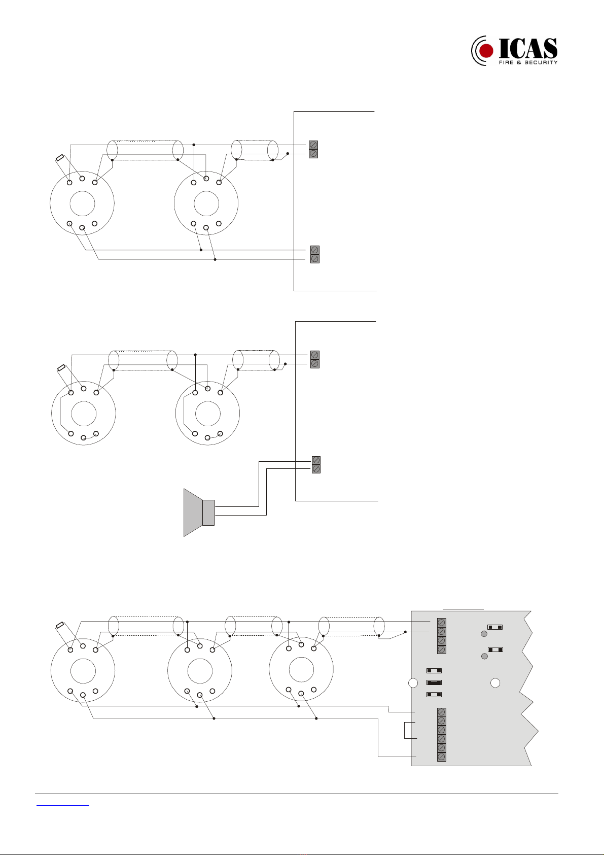
Siren
The siren/buzzer is integrated in the detector, but electrically isolated from it. At the base it is 2 terminals for the siren connection. -Sir (5) & +Sir (6). Siren
voltage is 12V to 24V. The connection is polarity protected. Filter against EMC is a part of the solution.
Maintenance
The detector shall be maintained with regularity, especially against dust or other airborne particles included insects. If it is suspected insects inside the detector,
the detector can be put into a clear airtight plastic bag for 24 hours, to see if any insects will get out. Be aware that dirty environment do make a wear and tear
situation on the detector, and after some years they will be signalling time for change-out!!
Detector status:
Signal-colour Signal-type Status detector Action / Comments
No Light None - Normal operation
- Heat/Smoke sensitivity tests every 4sec.
- Complete detector test every 4 sec.
Yellow 2 short blink every 4.
sec. up to 40 sec.
- Start up detector.
- Start up or registration in memory
- Blinking until detector chamber is stabilised. Can vary from
1 to 40sec.dependig of detector type.
Blink every 4. sec. - Chamber / Sensor faulty
- Program Faulty (Check-sum error)
- Event saved to memory
- Fault counter increase +1.
- Rengjør, eventuelt bytt detektor
- Remove power for approx.1min.Change the detector if still
not working.
4 short blink in intervals - ”Watch-Dog” control detects a stalled
program.
- Smoke/Heat sampling is done
- The event being stored in memory
- WD-counter increases with +1.
- ”Watch-Dog” checks every 4.sec. If program freeze, it will
restart the detector automatically.
- Remove power from detector for 1 min. If this is not
working, remove and change detector.
Red One blink every 1. sec. - Pre alarm. Smoke has been detected. - After first smoke detection, the sampling increases from 4
to 1 sec.
Steady RED Led - The current in the loop increases and activate
Alarm and OPTO-output drops to 0V.
- Event is saved
- Alarm-counter increases +1
- When reason for alarm is found and there is no present fire,
the detector must be reset by removing the power for 2
seconds.
Blink every10 sec., for
a period less than
10sec.and then gone.
- Pre-ample that the test discovered an
object/smoke in the chamber
- It could have been an object in the chamber, which was
taken as smoke.
Tekniske spesifikasjoner 500-IDx:
Type: 500-IDx (x=O, I, T)
Detector types:: IDO: Optical, IDI: Ionical, IDT: Heat/Temperature
Certified acc. to: EN54-7 (500-IDI, 500-IDO), EN54-5 (500-IDT)
Sensitivity: Acc. To EN54-7 (500-IDI og 500-IDO), EN54-5 Class A1 (500-IDT)
500-IDT: Alarm at approx. 60
0
C, Rate of Rise 9
0
C/min.
Power: 9-24VDC, polarity protected
Current consumption standby: Less than 50 µA (can change when detector are being tested.)
Current consumption in alarm: 20 - 25mA
Siren power: 12-24 VDC. Polarity protected (Input and output is EMC protected.).
Siren current: I<10mA. (The circuit is galvanic isolated from detector.)
Sound siren: 85 dB(A)/3 m .
Testing: Test gas – for 500-IDI & 500-IDO. Pre-warning after 4 sec. and a red blink every sec.
After 10 sec (10 samples) the detector will activate fire alarm and led will have steady red light.
Heat (i.e. hair dryer) 500-IDT
NB: The LED is not a push-button, DO NOT push!
With Diagnostic system (DS-500) and PC. Test report stored in PC or printed..
Memory: Memory stores the last 32 consecutive events in eeprom. (No Timing.)
Reset alarm: Remove power for a short period. (approx. 2 sec.).
Temp. : -10
o
C to +55
o
C
Humidity: 95%RH (No condensation)
Size: D=118mm, H=36mm, (H=42 mm included base)
Technical spec. 500-Re (relay Base):
Power: 9-24VDC
Resistive load: 0,5A v/125Vac, 1A v/30VDC
Max breaking current: 1A
Max Power: 125VAC, 48VDC
Max Breaking Power: 62,5VA, 33W
Temp: -10
o
C to +55
o
C
Dimensions: D=104mm, H=12mm, (build 6mm only when mounted to detector)
Humidity: 95%RH (No condensation)

www.icas.no Manual_500-IDx_Eng.doc Side 3/5
rev. 24.03.11
Alternative connection of internal siren
With this solution, all siren will be activated when the fire central activates the alarm/siren output.
Detector
500-ID(x)
1
(+U)
2
(0V) 3
(0V)
OPTO
4
-SIR
5
+SIR
6
1
(+U)
2
(0V) 3
(0V)
OPTO
4
-SIR
5
+SIR
6
Control Unit
Loop
Siren
+
+
_
_
EOL
Detector
500-ID(x)
Common siren
Powered from Control Unit
With this solution, the siren is controlled by the detector, and only this detector’s siren gives sound output
Detector
500-ID(x)
1
(+U)
2
(0V) 3
(0V)
OPTO
4
-SIR
5
+SIR
6
1
(+U)
2
(0V) 3
(0V)
OPTO
4
-SIR
5
+SIR
6
Control Unit
Loop
Siren
+
+
_
_
EOL
Detector
500-ID(x)
Local siren
(sound output on one siren only)
Siren
Note: Shielded cable. Shield connects to 0V in detector & control unit
Control unit IMC-ME
IMC-ME
+
-
+
-
L
o
o
p
1
L
o
o
p
2
+12V
0V
OCO
NO
NC
COM
Z1 - 12V
Z2 - 12V
SIR
BAT
DEL
Detector
500-ID(x)
EOL
(22k)
1
(+U)
2
(0V) 3
(0V)
OPTO
4
-SIR
5
+SIR
6
1
(+U)
2
(0V) 3
(0V)
OPTO
4
-SIR
5
+SIR
6
Detector
500-ID(x)
Detector
500-ID(x)
1
(+U)
2
(0V) 3
(0V)
OPTO
4
-SIR
5
+SIR
6

www.icas.no Manual_500-IDx_Eng.doc Side 4/5
rev. 24.03.11
Control unit IMC-M12V
Detector
500-ID(x)
EOL
(27k)
+
-
+
-
L
o
o
p
1
L
o
o
p
2
+12V
0V
SIR
NO
NC
COM
BAT
IMC-M12V
1
2
V
1
(+U)
2
(0V) 3
(0V)
OPTO
4
-SIR
5
+SIR
6
1
(+U)
2
(0V) 3
(0V)
OPTO
4
-SIR
5
+SIR
6
Detector
500-ID(x)
Detector
500-ID(x)
1
(+U)
2
(0V) 3
(0V)
OPTO
4
-SIR
5
+SIR
6
1
2
V
Control unit IMC-M
Detector
500-ID(x)
EOL
(22k)
+
-
+
-
L
o
o
p
1
L
o
o
p
2
+12V
0V
SIR
NO
NC
COM
BAT
IMC-M
9
V
9
V
1
(+U)
2
(0V) 3
(0V)
OPTO
4
-SIR
5
+SIR
6
1
(+U)
2
(0V) 3
(0V)
OPTO
4
-SIR
5
+SIR
6
Detector
500-ID(x)
Detector
500-ID(x)
1
(+U)
2
(0V) 3
(0V)
OPTO
4
-SIR
5
+SIR
6
Fire central ALPHA 4/8/12 (EN 54)
1
2
3
4
5
6
7
8
9
1
2
3
4
5
6
7
8
9
1
0
1
1
1
2
1
3
1
4
1
5
1
6
Loop 4
Loop 3
Shield
Loop 2
Loop 1
Sounders
Alarm 4
Alarm 3
Alarm 2
Alarm 1
Alarm-
output
Error-
output
Input
Output
Alpha
Com
Nc
No
Com
Nc
No
0V
24V
Detector
500-ID(x)
EOL
(3,9k)
1
(+U)
2
(0V) 3
(0V)
OPTO
4
-SIR
5
+SIR
6
1
(+U)
2
(0V) 3
(0V)
OPTO
4
-SIR
5
+SIR
6
Detector
500-ID(x)
Detector
500-ID(x)
1
(+U)
2
(0V) 3
(0V)
OPTO
4
-SIR
5
+SIR
6

www.icas.no Manual_500-IDx_Eng.doc Side 5/5
rev. 24.03.11
Intruder central JA-82K, with relay base 500-Re
Detector
500-ID(x)
1
(+U)
2
(0V) 3
(0V)
OPTO
4
-SIR
5
+SIR
6
Detector
500-ID(x)
Detector
500-ID(x)
NO
NC
CO M
1
(+U)
2
(0V) 3
(0V)
OPTO
4
-SIR
5
+SIR
6
NO
NC
CO M
1
(+U)
2
(0V) 3
(0V)
OPTO
4
-SIR
5
+SIR
6
NO
NC
CO M
1K
1K 1K 1K
Intruder/Fire, w/relay base 500-Re (loop NO) - 0V connected on terminal 3 only, to prevent loss of voltage to the other detectors, in case one is removed.
Detector
500-ID(x)
1
(+U)
2
(0V) 3
(0V)
OPTO
4
-SIR
5
+SIR
6
Detector
500-ID(x)
Detector
500-ID(x)
9: NO
7: NC
8: COM
1
(+U)
2
(0V) 3
(0V)
OPTO
4
-SIR
5
+SIR
6
9: NO
7: NC
8: COM
Loop
+
-
1
(+U)
2
(0V) 3
(0V)
OPTO
4
-SIR
5
+SIR
6
9: NO
7: NC
8: COM
Power
-
+
Siren output
+
-
This manual suits for next models
3
Table of contents
Other ICAS Fire Alarm manuals
Popular Fire Alarm manuals by other brands

pivotal
pivotal CurrentLeak Whole Home installation instructions

Eaton
Eaton xDetect Large Panel Installation and operation manual

Teletek electronics
Teletek electronics SensoIRIS BSOU Installation instruction

Siemens
Siemens FC2005 Programming manual

Mircom
Mircom MPS-800MP Series manual

LIFETONE
LIFETONE HLAC100 user manual