ICC PBDP-110 User manual

October 2001
ICC #10407-V1.00-000
ADJUSTABLE SPEED DRIVE NETWORK INTERFACE
PBDP-110
PROFIBUS-DP COMMUNICATIONS INTERFACE
FOR THE TOSHIBA 7-SERIES AND 9-SERIES
ADJUSTABLE SPEED DRIVES

1
Introduction
Thank you for purchasing the ICC PBDP-110 Profibus-DP Communications Interface
for the Toshiba 7-Series and 9-Series Adjustable Speed Drives. Before using the
PBDP-110 interface, please familiarize yourself with the unit and be sure to
thoroughly read the instructions and precautions contained in this manual. In
addition, please make sure that this instruction manual is delivered to the end user of
the drive units with which the PBDP-110 interface is connected, and keep this
instruction manual in a safe place for future reference or drive/interface inspection.
This instruction manual describes the device specifications, wiring methods,
maintenance procedures, supported functions and usage methods for the PBDP-110
Profibus-DP communications interface.
In conjunction with this manual, the following manuals are supplied by Toshiba, and
are essential both for ensuring a safe, reliable system installation as well as for
realizing the full potential of the PBDP-110 interface:
• Toshiba TOSVERT VF-S7 Series Instruction Manual
• Toshiba TOSVERT VF-S9 Series Instruction Manual
• Toshiba TOSVERT VF-A7 Series Instruction Manual
• Toshiba G7 Series Operation Manual
• Toshiba VF-S7 Industrial Inverter Serial Communications Option Manual
If you do not have copies available of the documents relevant to your installation,
please contact Toshiba or your local Toshiba distributor to obtain them, or copies
may be downloaded from http://www.tic.toshiba.com (subject to availability).
Before continuing, please take a moment to ensure that you have received all
materials shipped with your kit. These items are:
• External PBDP-110 interface in DIN rail mountable case
• 2 meter DB9-RJ45 MMI port cable (part number 10369)
• This manual

2
PBDP-110 Profibus-DP Interface User's Manual
Part Number 10407-V1.00-000
Printed in U.S.A.
©2001-2002 Industrial Control Communications, Inc.
All rights reserved
Industrial Control Communications, Inc. reserves the right to make changes and
improvements to its products without providing notice.
Notice to Users
INDUSTRIAL CONTROL COMMUNICATIONS INC.’S PRODUCTS ARE NOT
AUTHORIZED FOR USE AS CRITICAL COMPONENTS IN LIFE-SUPPORT
DEVICES OR SYSTEMS. Life-support devices or systems are devices or systems
intended to sustain life, and whose failure to perform, when properly used in
accordance with instructions for use provided in the labeling and user's manual, can
be reasonably expected to result in significant injury.
No complex software or hardware system is perfect. Bugs may always be present in
a system of any size. In order to prevent danger to life or property, it is the
responsibility of the system designer to incorporate redundant protective mechanisms
appropriate to the risk involved.

3
Usage Precautions
• Please use the PBDP-110 only when the ambient temperature of the
environment into which the PBDP-110 is installed is within the following
specified temperature limits:
Operation: -10 ∼+50°C (+14 ∼+122°F)
Storage: -40 ∼+85°C (-40 ∼+185°F)
• Avoid installation locations that may be subjected to large shocks or vibrations.
• Avoid installation locations that may be subjected to rapid changes in
temperature or humidity.
Operating Environment
• Do not touch charged parts of the drive such as the terminal block while the
drive’s CHARGE lamp is lit. A charge will still be present in the drive’s internal
electrolytic capacitors, and therefore touching these areas may result in an
electrical shock. Always turn all drive input power supplies OFF, and wait at
least 5 minutes after the CHARGE lamp has gone out before connecting
communication cables or motor wiring.
• Proper ground connections are vital for both safety and signal reliability
reasons. For proper grounding procedures, please refer to the section in this
manual pertaining to grounding (section 4).
• Route all communication cables separate from the drive’s input/output power
wiring.
• To avoid the possibility of electric shock due to leakage currents, always
ground the drive’s E/GND terminal and the motor. To avoid misoperation, do
not connect the PBDP-110’s Profibus shield terminal to either of the above-
mentioned grounds or any other power ground.
• When making connections between the PBDP-110 and the drives, do not use
cables that exceed 5 meters in length.
• For further drive-specific precaution, safety and installation information, please
refer to the appropriate Toshiba documentation supplied with your drive.
Installation •
••
•Wiring
• Do not touch or insert a rod or any other item into the PBDP-110’s case while
power is applied, as this may lead to electrical shock or device damage.
• Commission the disposal of the PBDP-110 to a specialist.
• Do not assign the same network address to more than one PBDP-110 station
in the same network. For a detailed explanation of station addressing, refer to
section 8.
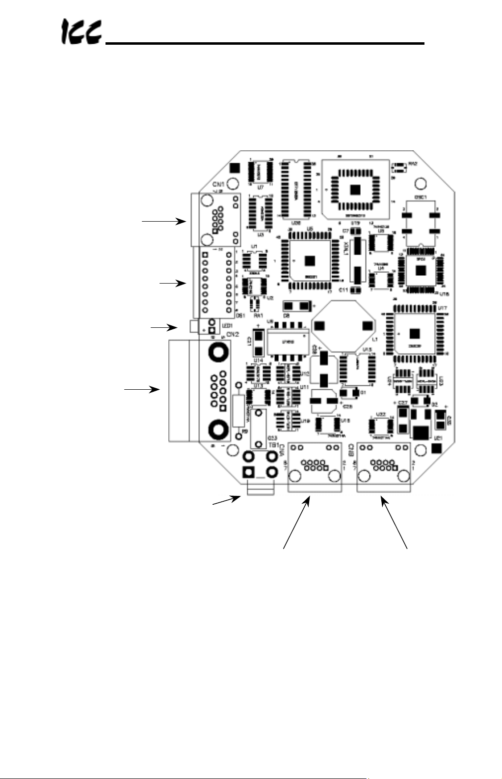
• Because the PBDP-110 derives its control power from the drive connected to
Channel A, removing power from that drive will also cause the PBDP-110 to
lose power, even if power is still applied to the drive connected to channel B.
• When only 1 drive is connected to the PBDP-110, it must be connected to
Channel A.
Other Precautions

4
TABLE OF CONTENTS
1. Mechanical Diagrams........................................................................... 5
1.1
Enclosure .........................................................................................................5
1.2
Mounting Clip ...................................................................................................6
1.3
External Interface.............................................................................................7
2. Feature Summary ................................................................................. 8
3. Installing The Interface ...................................................................... 12
3.1
Installation for G7 Drives ................................................................................12
3.2
Installation for S7, S9 and A7 Drives..............................................................13
4. Grounding ........................................................................................... 15
5. Environmental Specifications ........................................................... 15
6. Maintenance And Inspection............................................................. 16
7. Storage And Warranty........................................................................ 17
7.1
Storage ..........................................................................................................17
7.2
Warranty ........................................................................................................17
8. Selecting the Profibus Network Address ......................................... 18
9. Exchanged Data Structures............................................................... 20
9.1
Output (Control) Data Format.........................................................................20
9.2
Input (Status) Data Format.............................................................................23
9.3
Diagnostics ....................................................................................................26
10. Parameter Register Access ............................................................... 27
10.1
Parameter Number / Action Output Words .................................................27
10.2
Parameter Number / Action Input Words....................................................28
10.3
Parameter Access Procedure .....................................................................29
10.4
Register Access Error Codes......................................................................30
11. Parameter Registers .......................................................................... 31
12. MMI Port Use / GSD Files................................................................... 32
13. Notes ................................................................................................... 33

5
1. Mechanical Diagrams
1.1 Enclosure
(All units are in inches)

6
1.2 Mounting Clip
(All units are in inches)

7
1.3 External Interface
Note that for clarity the above diagram shows the PBDP-110 unit removed from its
case. However, it is not necessary to remove the unit from its case in order to
install or configure the PBDP-110.
Data_Exchange
LED
SHIELD grounding terminal
(refer to Section 4).
Profibus
network
connector
Drive “A” connector Drive “B” Connector
Address selection
DIP switches
MMI port

8
2. Feature Summary
The PBDP-110 interface provides a wide array of network data access and drive
control features. Combined with the flexible configuration and high-speed data
transfer capabilities of the Profibus network, this allows powerful networked control
and monitoring systems to be designed. Some of the main features provided by the
PBDP-110 which allow for this control and configurability are briefly described here:
Protocol
Profibus DP (Decentralized Periphery) as specified in European standard EN 50170.
The PBDP-110 can also co-exist simultaneously on networks using Profibus-FMS.
Network Baud Rates
Supports all Profibus baud rates from 9.6kbaud to 12Mbaud. The network baud rate
is automatically detected and continuously monitored during operation; no parameter
settings are necessary.
Drive Connections
The PBDP-110 provides support for simultaneous connection of two 7-series or 9-
series Toshiba drives. Both drives share a common Profibus station address. By
supporting 2 drives per interface, the maximum number of drives that can be
connected to 1 Profibus network segment without requiring repeaters increases from
31 (31 drives + 1 master) to 62 (31 PBDP-110 units + 1 master).
Power Supply
Self-contained. Powered directly from the drive connected to the Channel A
communications port. No external power supply devices or connections are required.
Isolation
The PBDP-110 has 3 separate isolated circuitry sections. Each drive is fully optically
isolated from each other, and both drives are optically isolated from the Profibus
network. By using optically isolated connections to the drives and the Profibus
network, grounding differential problems are eliminated and noise immunity
characteristics are greatly improved.
Drive AutoScan Algorithm
Connections to the drives are automatically established and continuously monitored.
No drive configuration needs to be performed to connect the PBDP-110 and
communicate via the Profibus network. Just plug it in – it’s that simple.

9
Global Control Functions
• Freeze mode: Input (monitor) data values are held constant within the PBDP-110
until the next “freeze” command or an “unfreeze” command is
received. Used primarily for synchronized monitoring of multiple
Profibus nodes.
• Sync mode: Output (control) data values are held constant within the PBDP-
110 until the next “sync” command or an “unsync” command is
received. Used primarily for synchronized control of multiple
Profibus nodes.
• Clear_Data: All output (control) data values are cleared to “0”.
Network Watchdog
A network watchdog function is always operating within the PBDP-110. In the event
of a disconnection from the Profibus network or loss of the network master, the
PBDP-110 can automatically switch any attached drives over to local control (if
selected at time of unit commissioning).
Indicators
• 1 green LED is provided to indicate when the PBDP-110 has achieved the
DATA_EXCHANGE state with the Profibus network master. This serves as a
convenient indicator that the Profibus master and PBDP-110 are configured
properly and are exchanging data.
• 1 green LED on the MMI interface port. The context is application-specific,
but under normal operation blinks at a 0.5Hz rate as a “heartbeat” indicator.
Also indicates data transfer when used with the Flashloader programming
utility.
• 1 green LED on each of the Channel A and Channel B drive connectors,
which indicate that the port is receiving power from the corresponding drive.
Profibus Network Connector
The network interface is a standard DB9 female connector with the following signals
provided:
Pin Number Function In/Out
3 Profibus network “B” (positive) data line In/out
4 RTS signal – direction control for fiber optic network
interface Out
5 DGND – power supply ground internally connected to the
interface board’s isolated ground -
6 VP – power supply +5v internally connected to the
interface board’s isolated P5. -
8 Profibus network “A” (negative) data line In/out
9 RTS signal ground reference – internally connected to the
interface board’s isolated ground -
1, 2, 7 No connection -

10
In addition to the above signals, the metallic housing of the DB9 connector is
connected to the shield section of the interface board. The shield section is attached
to the metal ground terminal on the bottom of the unit, where a ground wire can be
attached to connect the Profibus network cable shield to ground. Refer to section 4
of this document for more information related to grounding.
Drive Network Connectors
TTL-level. Uses standard RJ-45 style 8-pin modular connectors. Any standard
category-5 Ethernet cable (found in most electronics stores) 5 meters or less in
length can be used to connect the PBDP-110 to the drives.
MMI Port Connector
RS232-level. Use the DB9-to-RJ-45 cable supplied with the PBDP-110 kit to
interface with the unit via the Flashloader programming utility (refer to section 12).
Input/Output Data
The PBDP-110 presents a module interface, supporting 2 different modules
depending on the number of drives connected to the unit.
If the PBDP-110 is configured for 1 drive (the Channel A drive), the interface’s cyclic
data sizes are fixed at 16 bytes of output (control) data configured as four 32-bit
words, and 24 bytes of input (status) data configured as six 32-bit words.
If the PBDP-110 is configured for both drives (Channel A and B), the interface’s
cyclic data sizes are fixed at 32 bytes of output (control) data configured as eight 32-
bit words, and 48 bytes of input (status) data configured as twelve 32-bit words.
Via these data structures, any data item (commands, monitor data and parameters)
available in the drive can be accessed. For detailed explanations of the format and
usage of this data, refer to sections 9 and 10 of this document.
Versatile 3-Way DIN-Rail Mounting System
The interface unit enclosure is provided with a mounting clip attached to the rear of
the unit. This clip allows the unit to be mounted 3 different ways:
• For DIN rail mounting, snap the mounting clip onto a standard DIN rail, and
then snap the unit enclosure onto the clip’s retaining tabs. This allows easy
removal or repositioning of the unit on the DIN rail during wiring.
• For panel mounting, the mounting clip can be bolted directly to a flat panel via
the two bolt holes at the top and bottom of the clip. Refer to section 1.2 for
mounting clip mechanical details. Once the mounting clip is securely
attached to the panel, the unit enclosure can be snapped onto the clip’s
retaining tabs.
• For fixed DIN rail mounting, a combination of the above two techniques can
be employed. First, snap the mounting clip onto a DIN rail and position it in its
desired location. Then, the mounting clip can be bolted to the DIN rail support

11
panel, securing it in place. Lastly, the unit can be snapped onto the fixed
mounting clip.
In all cases, the unit can be easily unsnapped from the mounting clip to temporarily
provide easier access to the configuration switches or connectors.

12
3. Installing The Interface
The PBDP-110 connects to each drive via the drive’s common serial (logic level)
communication port, typically located on either the main drive control board (G7), on
the front of the drive enclosure under a small snap-on cover (A7, S9), or on the right-
hand side of the drive enclosure under a small snap-on cover (S7). Although no
drive parameters need to be configured in order to use the PBDP-110, it is
advantageous to check that the drive’s common serial communication data rate is set
to its maximum speed. Because the PBDP-110 will communicate to each drive only
at the drive’s configured data rate, this will provide the fastest response time for
drive-to-network data transfers. For information on checking the drive’s common
serial communication data rate, refer to the appropriate manual supplied with your
drive.
Note that this drive communication data rate setting is independent of the Profibus
network data rate, which is configured solely by the Profibus master station. Also
note that the common serial communication parameters of each drive are handled
independently by the PBDP-110, which means that different drive families may be
connected to different channels of the unit in any combination, and that the drives
connected to each channel may simultaneously communicate to the unit at
completely different baud rates, parity settings, etc.
Installation of the PBDP-110 Profibus interface should only be performed by a
qualified technician familiar with the maintenance and operation of the connected
drives. To install the PBDP-110, complete the following steps:
3.1 Installation for G7 Drives
1.
CAUTION!
Verify that all input power sources to the drives to be
connected have been turned OFF and are locked and tagged out.
2.
DANGER!
Wait at least 5 minutes for the drive’s electrolytic
capacitors to discharge before proceeding to the next step. Do not touch any
internal parts with power applied to the drive, or for at least 5 minutes after
power to the drive has been removed. A hazard exists temporarily for
electrical shock even if the source power has been removed. Verify that the
CHARGE LED has gone out before continuing the installation process.
3. Attach the mounting clip and unit enclosure in your desired manner (refer to page
10 for more information).
4. Remove the drive’s front cover / open the drive’s cabinet door (refer to the
appropriate drive manual for instructions how to do this).
5. The drive’s Electronic Operator Interface (EOI) can communicate with the drive
via either the RS485/RS232 channel (CNU1/CNU1A) or the common serial
channel (CNU2/CNU2A). Because the PBDP-110 uses the common serial
channel, the EOI must be configured to use the RS485/RS232 channel. If the
drive to be connected is currently using CNU2 (on the drive control board) and

13
CNU2A (on the EOI), then this connection must first be switched over to CNU1
(on the drive control board) and CNU1A (on the EOI). Refer to Toshiba’s
documentation for any precautions or notices regarding this connection change.
If the EOI is already connected via the RS485/RS232 channel, then no change is
required.
6. Connect the drive’s common serial communication port (CNU2) to “Channel A” of
the PBDP-110 with the communication cable (communication cable is not
included with the interface kit). When choosing cables for this connection,
standard 24 AWG category 5 (CAT5) unshielded twisted-pair (UTP) 8-conductor
cables found in Ethernet networks in most office environments can be used. The
maximum allowable length for these cables is 5 meters. Although there are many
varieties and styles of CAT5 UTP cables available, ICC strongly recommends
using only high-quality cables from reputable manufacturers to guarantee optimal
noise immunity and cable longevity. Ensure that each end of the cable is fully
seated into the modular connector, and route the cable such that it is located well
away from any drive input power or motor wiring. Also take care to route the
cable away from any sharp edges or positions where it may be pinched.
7. Reinstall the drive’s front cover / close the drive’s cabinet door.
8. Repeat steps 1, 2, 4, 5, 6 and 7 to connect another drive to “Channel B” on the
interface, if desired.
9. Connect the Profibus network cable to the DB9 connector marked “Network” on
the PBDP-110. If a ground cable is going to be used, attach the ground cable to
the terminal marked “Shield GND” on the bottom side of the PBDP-110 enclosure
(refer to section 4). Refer to the Profibus Specification for detailed network wiring
guidelines. Ensure that the Profibus network cable is tightly screwed onto the
DB9 connector, and route the cable such that it is located well away from any
drive input power or motor wiring. Also take care to route the cable away from
any sharp edges or positions where it may be pinched.
10. Take a moment to verify that the PBDP-110 and all network cables have
sufficient clearance from drives, motors, or power-carrying electrical wiring.
11. Configure the Profibus slave address via the DIP switches on the front of the
interface (refer to section 8).
12. Turn the power sources to all connected drives ON, and verify that the drives
function properly. If the drives do not appear to power up, or do not function
properly, immediately turn power OFF. Repeat steps 1 and 2 to remove all
power from the drives. Then, verify all connections. Contact ICC or your local
drive distributor or manufacturer for assistance if the problem persists.
3.2 Installation for S7, S9 and A7 Drives
1.
CAUTION!
Verify that all input power sources to the drives to be
connected have been turned OFF and are locked and tagged out.
2.
DANGER!
Wait at least 5 minutes for the drive’s electrolytic
capacitors to discharge before proceeding to the next step. Do not touch any
internal parts with power applied to the drive, or for at least 5 minutes after

14
power to the drive has been removed. A hazard exists temporarily for
electrical shock even if the source power has been removed. Verify that the
CHARGE LED has gone out before continuing the installation process.
3. Attach the mounting clip and unit enclosure in your desired manner (refer to page
10 for more information).
4. Remove the drive’s common serial communication port cover (refer to the
appropriate drive manual for instructions how to do this). Do not discard this
cover, as it should be reinstalled to minimize contamination of the port’s electrical
contacts if the interface is ever disconnected from the drive.
5. Connect the drive’s common serial communication port to “Channel A” of the
PBDP-110 with the communication cable (communication cable is not included
with the interface kit). When choosing cables for this connection, standard 24
AWG category 5 (CAT5) unshielded twisted-pair (UTP) 8-conductor cables found
in Ethernet networks in most office environments can be used. The maximum
allowable length for these cables is 5 meters. Although there are many varieties
and styles of CAT5 UTP cables available, ICC strongly recommends using only
high-quality cables from reputable manufacturers to guarantee optimal noise
immunity and cable longevity. Ensure that each end of the cable is fully seated
into the modular connector, and route the cable such that it is located well away
from any drive input power or motor wiring. Also take care to route the cable
away from any sharp edges or positions where it may be pinched.
6. Repeat steps 1, 2, 4 and 5 to connect another drive to “Channel B” on the
interface, if desired.
7. Connect the Profibus network cable to the DB9 connector marked “Network” on
the PBDP-110. If a ground cable is going to be used, attach the ground cable to
the terminal marked “Shield GND” on the bottom side of the PBDP-110 enclosure
(refer to section 4). Refer to the Profibus Specification for detailed network wiring
guidelines. Ensure that the Profibus network cable is tightly screwed onto the
DB9 connector, and route the cable such that it is located well away from any
drive input power or motor wiring. Also take care to route the cable away from
any sharp edges or positions where it may be pinched.
8. Take a moment to verify that the PBDP-110 and all network cables have
sufficient clearance from drives, motors, or power-carrying electrical wiring.
9. Configure the Profibus slave address via the DIP switches on the front of the
interface (refer to section 8).
10. Turn the power sources to all connected drives ON, and verify that the drives
function properly. If the drives do not appear to power up, or do not function
properly, immediately turn power OFF. Repeat steps 1 and 2 to remove all
power from the drives. Then, verify all connections. Contact ICC or your local
drive distributor or manufacturer for assistance if the problem persists.

15
4. Grounding
Grounding is of particular importance for reliable, stable operation. Communication
system characteristics may vary from system to system, depending on the system
environment and grounding method used. The PBDP-110 Profibus interface is
provided with a “Shield GND” terminal on the bottom of the unit. The “Shield GND”
terminal is directly connected to the metallic housing of the DB9 connector, which
should in turn be connected to the shield of the Profibus network cable through the
Profibus connector. To ground the network cable shield, therefore, connect a wire to
the Shield GND terminal, and then connect the other end of the wire to an
appropriate ground. For specific requirements regarding protective grounding and
the Profibus network, refer to the Profibus Standard (EN 50 170, part 1).
Please be sure to consider the following general points for making proper ground
connections:
Grounding method checkpoints
1. Make all ground connections such that no ground current flows through the case
or heatsink of a connected drive.
2. Do not connect the PBDP-110 Shield GND terminal to a power ground or any
other potential noise-producing ground connection (such as a drive’s “E”
terminal).
3. Do not make connections to unstable grounds (paint-coated screw heads,
grounds that are subjected to inductive noise, etc.)
5. Environmental Specifications
Item Specification
Operating Environment Indoors, less than 1000m above sea level, do not
expose to direct sunlight or corrosive / explosive gasses
Operating Temperature -10 ∼+50°C (+14 ∼+122°F)
Storage Temperature -40 ∼+85°C (-40 ∼+185°F)
Relative Humidity 20% ∼90% (without condensation)
Vibration 5.9m/s
2
{0.6G} or less (10 ∼55Hz)
Grounding According to EN 50 170, part 1
Cooling Method Self-cooled

16
6. Maintenance And Inspection
Preventive maintenance and inspection is required to maintain the communication
interface in its optimal condition, and to ensure a long operational lifetime.
Depending on usage and operating conditions, perform a periodic inspection once
every three to six months. Before starting inspections, always turn off all power
supplies to connected drives, and wait at least five minutes after each drive’s
“CHARGE” lamp has gone out.
DANGER!
Do not touch any internal parts with power applied
to the drives, or for at least 5 minutes after power to the drives has been
removed. A hazard exists temporarily for electrical shock even if the source
power has been removed.
Inspection Points
• Check that the dust covers for all unused RJ45 ports are seated firmly in their
connectors.
• Check that the drive and network communication cables are not loose. Tighten /
reseat as necessary.
• Where applicable, check that there are no defects in any attached grounding wire
terminal crimp points. Visually check that the crimp points are not scarred by
overheating.
• Visually check all wiring and cables for damage. Replace as necessary.
• Clean off any accumulated dust and dirt.
• If use of the interface is discontinued for extended periods of time, apply power at
least once every two years and confirm that the unit still functions properly.
• Do not perform hi-pot tests on the drives or interface, as they may damage the
units.
Please pay close attention to all periodic inspection points and maintain a good
operating environment.

17
7. Storage And Warranty
7.1 Storage
Observe the following points when the communication interface is not used
immediately after purchase or when it is not used for an extended period of time.
• Avoid storing the unit in places that are hot or humid, or that contain large
quantities of dust or metallic dust. Store the unit in a well-ventilated location.
• When not using the unit for an extended period of time, apply power at least once
every two years and confirm that it still functions properly.
7.2 Warranty
This communications interface is covered under warranty by ICC for a period of 12
months from the date of installation, but not to exceed 18 months from the date of
shipment from the factory. For further warranty or service information, please contact
Industrial Control Communications, Inc. or your local distributor.

18
8. Selecting the Profibus Network Address
The 8-position piano-style “Address” DIP switches accessible from the front of the
unit allow selection of the Profibus slave address. Switch positions #1 ∼#7 select the
address. Switch position #8 is reserved for production test use, and should always
be kept in the “OFF” position. The PBDP-110 does not support the Profibus
“set_slave_address” service.
The address settings for the various switch configurations are as follows:
SW1 SW2 SW3 SW4 SW5 SW6 SW7 Addr SW1 SW2 SW3 SW4 SW5 SW6 SW7 Addr
OFF OFF OFF OFF OFF OFF OFF 0 OFF OFF OFF OFF OFF ON OFF 32
ON OFF OFF OFF OFF OFF OFF 1 ON OFF OFF OFF OFF ON OFF 33
OFF ON OFF OFF OFF OFF OFF 2 OFF ON OFF OFF OFF ON OFF 34
ON ON OFF OFF OFF OFF OFF 3 ON ON OFF OFF OFF ON OFF 35
OFF OFF ON OFF OFF OFF OFF 4 OFF OFF ON OFF OFF ON OFF 36
ON OFF ON OFF OFF OFF OFF 5 ON OFF ON OFF OFF ON OFF 37
OFF ON ON OFF OFF OFF OFF 6 OFF ON ON OFF OFF ON OFF 38
ON ON ON OFF OFF OFF OFF 7 ON ON ON OFF OFF ON OFF 39
OFF OFF OFF ON OFF OFF OFF 8 OFF OFF OFF ON OFF ON OFF 40
ON OFF OFF ON OFF OFF OFF 9 ON OFF OFF ON OFF ON OFF 41
OFF ON OFF ON OFF OFF OFF 10 OFF ON OFF ON OFF ON OFF 42
ON ON OFF ON OFF OFF OFF 11 ON ON OFF ON OFF ON OFF 43
OFF OFF ON ON OFF OFF OFF 12 OFF OFF ON ON OFF ON OFF 44
ON OFF ON ON OFF OFF OFF 13 ON OFF ON ON OFF ON OFF 45
OFF ON ON ON OFF OFF OFF 14 OFF ON ON ON OFF ON OFF 46
ON ON ON ON OFF OFF OFF 15 ON ON ON ON OFF ON OFF 47
OFF OFF OFF OFF ON OFF OFF 16 OFF OFF OFF OFF ON ON OFF 48
ON OFF OFF OFF ON OFF OFF 17 ON OFF OFF OFF ON ON OFF 49
OFF ON OFF OFF ON OFF OFF 18 OFF ON OFF OFF ON ON OFF 50
ON ON OFF OFF ON OFF OFF 19 ON ON OFF OFF ON ON OFF 51
OFF OFF ON OFF ON OFF OFF 20 OFF OFF ON OFF ON ON OFF 52
ON OFF ON OFF ON OFF OFF 21 ON OFF ON OFF ON ON OFF 53
OFF ON ON OFF ON OFF OFF 22 OFF ON ON OFF ON ON OFF 54
ON ON ON OFF ON OFF OFF 23 ON ON ON OFF ON ON OFF 55
OFF OFF OFF ON ON OFF OFF 24 OFF OFF OFF ON ON ON OFF 56
ON OFF OFF ON ON OFF OFF 25 ON OFF OFF ON ON ON OFF 57
OFF ON OFF ON ON OFF OFF 26 OFF ON OFF ON ON ON OFF 58
ON ON OFF ON ON OFF OFF 27 ON ON OFF ON ON ON OFF 59
OFF OFF ON ON ON OFF OFF 28 OFF OFF ON ON ON ON OFF 60
ON OFF ON ON ON OFF OFF 29 ON OFF ON ON ON ON OFF 61
OFF ON ON ON ON OFF OFF 30 OFF ON ON ON ON ON OFF 62
ON ON ON ON ON OFF OFF 31 ON ON ON ON ON ON OFF 63

19
(continued…)
SW1 SW2 SW3 SW4 SW5 SW6 SW7 Addr SW1 SW2 SW3 SW4 SW5 SW6 SW7 Addr
OFF OFF OFF OFF OFF OFF ON 64 OFF OFF OFF OFF OFF ON ON 96
ON OFF OFF OFF OFF OFF ON 65 ON OFF OFF OFF OFF ON ON 97
OFF ON OFF OFF OFF OFF ON 66 OFF ON OFF OFF OFF ON ON 98
ON ON OFF OFF OFF OFF ON 67 ON ON OFF OFF OFF ON ON 99
OFF OFF ON OFF OFF OFF ON 68 OFF OFF ON OFF OFF ON ON 100
ON OFF ON OFF OFF OFF ON 69 ON OFF ON OFF OFF ON ON 101
OFF ON ON OFF OFF OFF ON 70 OFF ON ON OFF OFF ON ON 102
ON ON ON OFF OFF OFF ON 71 ON ON ON OFF OFF ON ON 103
OFF OFF OFF ON OFF OFF ON 72 OFF OFF OFF ON OFF ON ON 104
ON OFF OFF ON OFF OFF ON 73 ON OFF OFF ON OFF ON ON 105
OFF ON OFF ON OFF OFF ON 74 OFF ON OFF ON OFF ON ON 106
ON ON OFF ON OFF OFF ON 75 ON ON OFF ON OFF ON ON 107
OFF OFF ON ON OFF OFF ON 76 OFF OFF ON ON OFF ON ON 108
ON OFF ON ON OFF OFF ON 77 ON OFF ON ON OFF ON ON 109
OFF ON ON ON OFF OFF ON 78 OFF ON ON ON OFF ON ON 110
ON ON ON ON OFF OFF ON 79 ON ON ON ON OFF ON ON 111
OFF OFF OFF OFF ON OFF ON 80 OFF OFF OFF OFF ON ON ON 112
ON OFF OFF OFF ON OFF ON 81 ON OFF OFF OFF ON ON ON 113
OFF ON OFF OFF ON OFF ON 82 OFF ON OFF OFF ON ON ON 114
ON ON OFF OFF ON OFF ON 83 ON ON OFF OFF ON ON ON 115
OFF OFF ON OFF ON OFF ON 84 OFF OFF ON OFF ON ON ON 116
ON OFF ON OFF ON OFF ON 85 ON OFF ON OFF ON ON ON 117
OFF ON ON OFF ON OFF ON 86 OFF ON ON OFF ON ON ON 118
ON ON ON OFF ON OFF ON 87 ON ON ON OFF ON ON ON 119
OFF OFF OFF ON ON OFF ON 88 OFF OFF OFF ON ON ON ON 120
ON OFF OFF ON ON OFF ON 89 ON OFF OFF ON ON ON ON 121
OFF ON OFF ON ON OFF ON 90 OFF ON OFF ON ON ON ON 122
ON ON OFF ON ON OFF ON 91 ON ON OFF ON ON ON ON 123
OFF OFF ON ON ON OFF ON 92 OFF OFF ON ON ON ON ON 124
ON OFF ON ON ON OFF ON 93 ON OFF ON ON ON ON ON 125
OFF ON ON ON ON OFF ON 94 OFF ON ON ON ON ON ON 126
ON ON ON ON ON OFF ON 95
Note that the “ON” position of each switch is the “down” position and that the “OFF”
position is the “up” position. Refer to the indicator markings on the switch.
The address switch settings are read by the interface only on power-up. Therefore, if
the address is changed, be sure to power the PBDP-110 off momentarily by cycling
power to the drive connected to “Channel A” or by disconnecting/reconnecting the
cable connecting “Channel A” to the drive.
Table of contents
Popular Network Hardware manuals by other brands

Digi
Digi Opengear OPERATIONS MANAGER 2200 quick start guide

TelcoBridges
TelcoBridges Tmedia TMG5800 Quick installation guide

Juniper
Juniper WX 15 quick start

Pepwave
Pepwave Surf AP 200-X installation guide

ADTRAN
ADTRAN NetVanta 2000 Series quick start guide

Patton electronics
Patton electronics ACC-S02 Specification sheet

HIK VISION
HIK VISION DS-9600 Series Quick operation guide

EZ CONNECT
EZ CONNECT SMC 2682W user guide

Teledyne Lecroy
Teledyne Lecroy PCI Express M.2 User manual and quick start guide

Cisco
Cisco ISA 3000 Connecting Instructions

Huawei
Huawei OptiX OSN 9560 Quick installation guide

Juniper
Juniper M-Series datasheet