ICD MFM 9012 User manual

1
INDUSTRIAL CONTROLS & DRIVES (INDIA) PRIVATE LIMITED
Old No:10, New No:33, Mettukuppam Road, (Via Alappakam Road),
Maduravoyal, Chennai - 600 095.
Phone : 4293 4324/4293 4325 FAX : 91-44-4293 4355
E-mail : sale[email protected] website : www.icdipl.net
OPERATING MANUAL FOR
MULTI FUNCTION METER
(Model: MFM 9012 - 45mm Depth)

2
CONTENTS
1. General Features ........................................ 3
2. Installation................................................... 4
3. Wiring Diagram.......................................... 6
4. Front Panel Features.................................. 9
4.1 Key Description.................................... 10
4.2 Changing the configuration Items.......... 10
5. Programming Instructions........................... 11
6. RUN Mode display pages............................ 14
7. Communication Port Details........................ 16
7.1 Communication connection diagram........ 18
8 Technical specification (class 0.5 & Class 1) 19

3
MULTI FUNCTION METER
1. General Features
The Meter is designed with latest state of art technology. It offers
high accuracy, reliability and also real value for money. This next
generation micro controller based instruments monitors over 25 vital
parameters and does not require any external Transducers. This
instrument is most suitable for measuring all electrical parameters in 3
phase industrial applications. It replaces several meters like Voltmeters,
Ammeters, Wattmeters, Frequency meter, kVA meter, kVAr meter, pf meter
and selector switches for the above in an electrical panel.
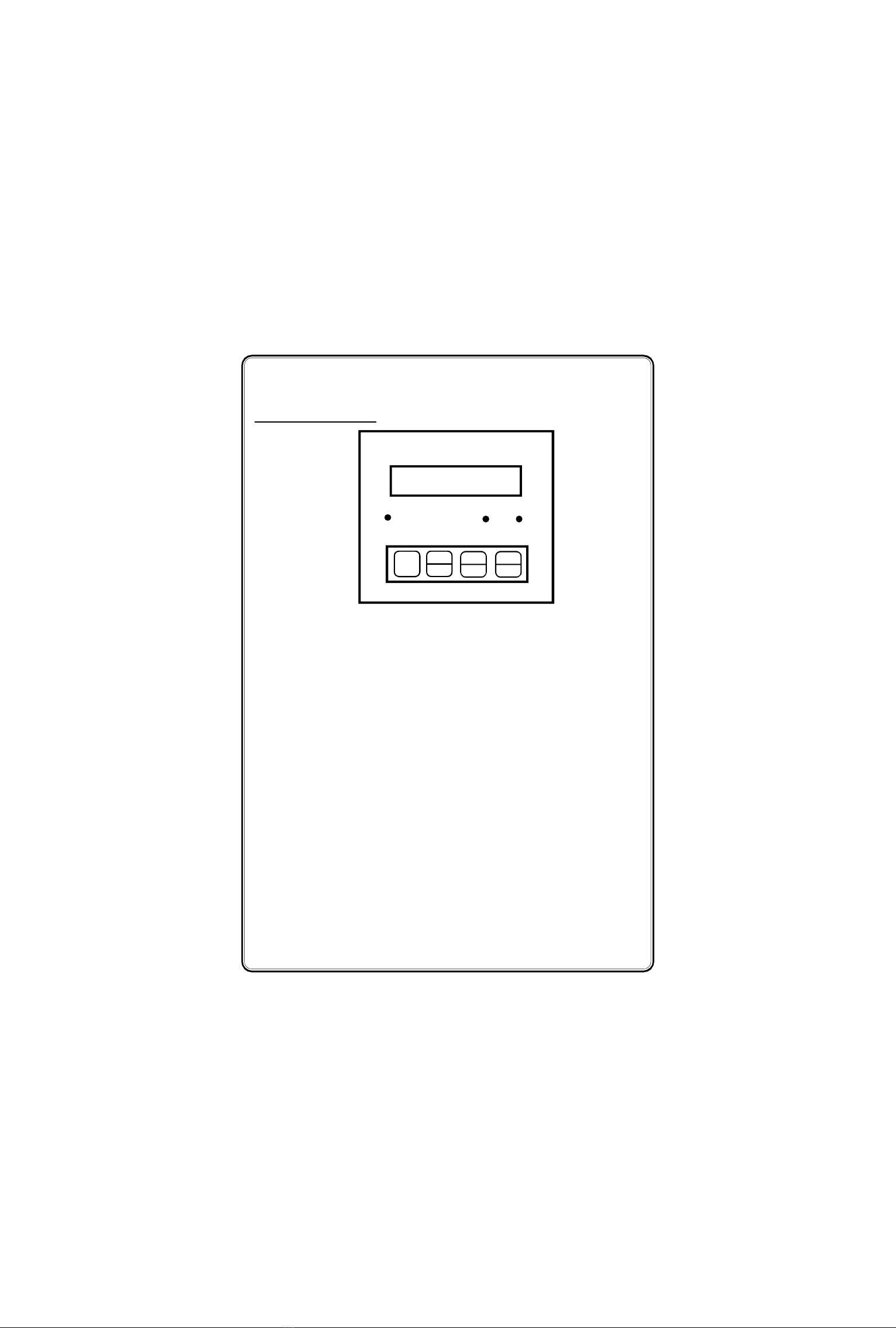
The measured informations are shown on a 2 row 16 character
LCD display with backlit. Four keys are provided on the front panel of the
meter to access these information easily and quickly. The front panel is
provided with antiglare feature for improved readability.
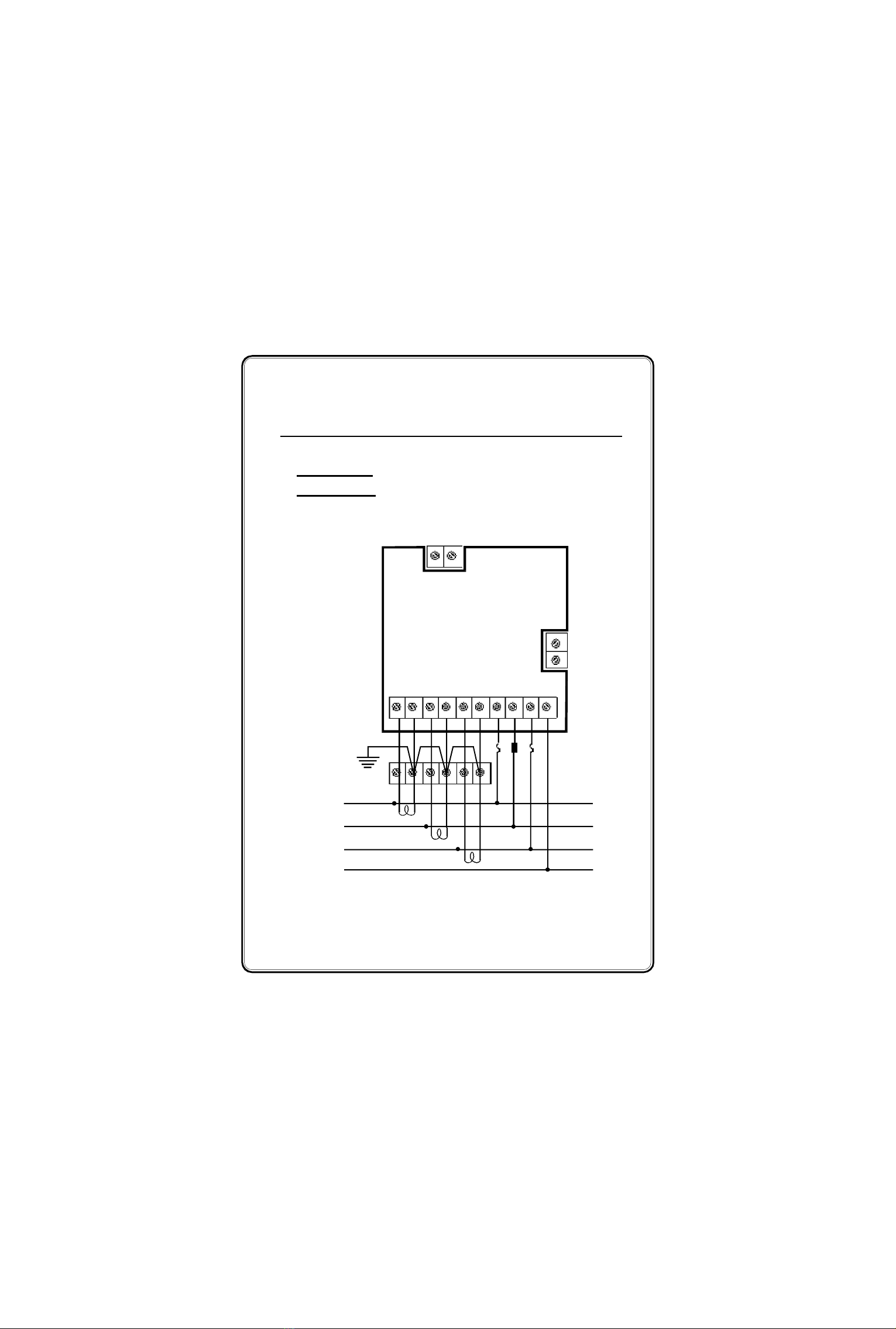
The measurement parameters include 3 phase voltage, 3 phase
current, kVA, kW, kVAr, PF, Frequency, kWh (or) kVAh. All voltage,
Current, Power and energy readings are true R.M.S including
harmonics. The power and energy measurement is done for the full four
quadrants. The energy reading is provided with reverse lock, showing
only the imported energy consumed by the consumer. The meter
computes and updates the parameters in every 2 seconds.
The meter is also provided with a optional RS 485 optically
isolated communication port supporting MOD BUS RTU protocol. The
port is very useful in networking the meters in multidrop communication
and to collect datas in a centralised control room using any standard
SCADA Software package like cimplicity, intellution, wonderware & citech
etc.
(Note : For Every change of LT HT or 1A 5A or 3 Wire 4
Wire the instrument should be switched OFF and then made ON.)

4
2. Installation
2.1. Mounting
The meter is housed in a compact ABS plastic enclosure of
dimension 96(H) x 96(W) x 45(D)mm. The meter is suitable for panel
mounting and has reliable mounting clamps to hold the meter to the
panel.
The panel cut out for fixing the meter is a 92 x 92 mm. The
depth behind the panel is 45 mm. Always provide extra space for the
connectors and wiring. The panel cut out should be punched with
proper tool and should be free from burrs. Insert the meter through
panel cutout from front and fix the mounting clamps provided with the
meter on each side. Tighten the fixing clamps with limit amount of force
so as to hold the meter in position.
2.2. Wiring
2.2.1 Selection of PT & CT
The measurement of voltage and current is done using the PT
voltage and CT current inputs. So the accuracy of measurement is
determined by the accuracy and phase shift produced by the PT’s and
CT’s so it is recommended to use PT’s and CT’s of instrument class
0.5 or better.
Also the PT’s and CT’s should have adequate VA rating to
support the burden on the secondary side of them. The primary rating
of the CT has to be selected such that the load variation lies between
the dynamic range of the CT. (30% to 80% of the primary current).

5
2.2.2 Voltage signal connections
The Meter directly accepts voltages upto 415VAC R.M.S line to
line (240VAC R.M.S line to neutral) with 10% over load capacity in
case of LT meters and 110VAC R.M.S line to line (63.5 VAC R.M.S line
to Neutral) with 10% over load capacity in case of HT meters. The
primary of the PT is field programmable upto 330 kV.
There are four voltage input terminals marked as R, Y, B & N.
The three phase input voltage should be connected to those
terminals.
Meter voltage input burden : 0.25VA per phase
2.2.3 Current signal connections
The Meter current inputs can accept both 5A AC or 1A AC
R.M.S (selectable) for connecting external CT’s. The CT Primary &
Secondary value is field programmable. In both the cases, the current
inputs has over load capability of 120%.
There are three pairs of terminals marked as IR (M,L) IY (M,L)
and IB (M,L) for the connection of external CT’s. For proper
measurements, the polarity of the CT’s must be connected properly.
The CT wiring must be properly done by deenergising the CT
secondary by shorting it through a shorting block. The primary current
of CT is field programmable upto 10000A.
Meter Current input burden : 0.25VA per phase

6
3. Wiring Diagram
3.1) Three phase four wire LT systems (3 watt measurement)
Voltage Input : Direct 240V(L-N)/415(L-L)V AC (-20% to +10%)
Current Input : 5/1A provide through 3 CT’s
L N
(90 - 270V AC/DC)
Auxiliary
D+
D-
Earth
Panel
Ground
To Load
CT’s
R
Y
B
N
Import
CT
Shorting
block
M L M L M L R Y B N
IR IY IB
RS 485

7
3.2) Three phase three wire HT systems (2 watt measurement)
Voltage Input : 110V AC (L - L)(Through PT)
Current Input : 5/1A provide through 2 CT’s
D+
D-
Earth
Panel
Ground
To Load
CT’s
R
Y
B
Import
CT
Shorting
block
M L M L R Y B
IR IB
RS 485
L N
(90 - 270V AC/DC)
Auxiliary

8
3.3) Auxiliary power supply connections
The Meter derives power from auxiliary power supply terminals
which is seperatly provided in the meter. SMPS circuit is used to power
up the meter so it can work from th range of 90 - 270V AC/DC. The
auxiliary supply should be connected to proper specified voltage.
Burden on Auxiliary supply terminals : 4VA
3.4) Cross checking the wiring
Three phase voltage wiring and current wiring are to be properly
done for correct measurements. Any wrong connections done either
during installation or during rewiring can produce wrong measurement of
electrical parameters. These incorrect wirings are difficult to detect since
they produce wrong readings close to the expected readings.
The Meter has a built in program to identify the reverse sequences
in PTas well as CT wiring. A seperate diagnostic display page is provided
to view the PT, CT Connections. IT can be selected by pressing the Shift
Key repeatedly.
If the PT & CT wiring are done correctly. The diagnostic page as
shows as
Otherwise the phase in which voltage connections or current
connections are wrongly connected is displayed.
While checking the wiring through the diagnostic page, make sure
the load current is 10% above the full scale current and also the load is
in import mode.
Note :(PT shows “RYB” when sequence connected is correct (RYB, YBR & BRY) or
else shows “RBY’, if sequence connected is incorrect (RBY, YRB & BYR). CT shows
reversal, when CT not synchronised with PT or wiring are Interchanged/Reversed or
Load in Export Mode.
PT SEQ : RYB
CT REVR : NIL

9
Multi Function Meter
The LCD Display is a 2 row 16 character Alpha numeric display
with backlit. The LCD Display is used to display voltage, current, kVA,
kW, kVAr, PF, Freq., kWh / kVAh, Run Hour, THD (if applicable) & pro-
gram mode settings. The LCD backlit is switched off when no key is
pressed for 3 minutes to save power and to enhance the life of LCD.
The LCD backlit is switched ON, when any key is pressed.
The TxD and RxD LED’s are provided to Indicate the activity in
the communication port. The RxD LED flashes, whenever the data is
received through communication port and the TxD LED flashes when
data is transmitted from the meter. These LED’s are not provided in
the meters without communication port. Calibration pulse output is
provided through 3mm RED LED in front panel. Meter constant is 3200
impulse/kWh.
The front panel is also provided with 4 keys. The key
descriptions are given below.The keys are used to select the
respective parameters in the normal operating mode and to
configure various items in the program mode.
4. Front Panel Features
TXD RXD
2 row 16 character
LCD Display
3200
imp/kWh
#
MORE
MULTI FUNCTION METER
ICD www.icdipl.net MFM 9012

10
Keys Program mode Normal operating mode
Index key
(To select Menus)
Shift Key
(To move between characters
& to select parameters)
Increment Key
(To increment the selected
digit & to select parameters)
Enter Key
(To store the modifications &
datas)
#
SCRL/HLD
MORE
SCRL/HLD
(To switch between Scroll/Hold
mode)
To increment Display
pages
To decrement Display
pages
More Key
(To view further sub pages)
4.1 Key Description :
4.2 Changing the configuration Items
In program mode, after selecting the configuration item through
Index key, It can be altered by using shift, Increment & Enter key.
The shift () key is used to select the digit one by one. The
selected digit is shown by flashing that digit.
The Increment () key is used to increment the selected
digit. The increment key Increments the digit from 0 to 9 and then wraps
down to zero once again. Shift and Increment keys are also used for
selecting the required parameter.
Once the required values are set in the configuration items
press the Enter key to store it in memory. If the change is accepted
the display Indicates ‘E’ otherwise an error message is displayed as
‘Error’.
Once the configuration Items are programmed hold in the
& keys together for 3 seconds to return back to normal operating
mode.

11
5. Programming Instructions
All meters are to be programmed properly to work in a
particular Installation. The various items that are to be programmed
are shown in the table below.
Configuration Item In Meter
New pass word In All meters
Primary Voltage In All meters
Secondary Voltage In All meters
Primary Current In All meters
Secondary Current In All meters
Wiring Type In All meters
Modbus Address Meters with Communication Interface only
kWh & Run Hour reset All meters
The Meters are provided with password facility to prevent
alteration of configuration items by unauthorised persons. The
configuration Items of the meter may be changed by following the
sequence given below.
With power applied to the meter hold in the& keys (shift
and Incr) together for 3 seconds. The display Indicates enter
password
The password set in the menu, “new password” has to be
entered by using Shift, Incr and enter keys (Refer changing the
configuration items for using Shift, Incr and Enter keys). After valid
password is entered the meter enters into program mode by showing it
in display.
Special Note :
If the user enters the ‘Enter pass word’ for the first time, or if the user fails to
remember the password entered in ‘New pass word’, the default password 0386
can be entered.
PROG PASS WORD
/ / / /
PROGRAM MODE

12
The configuration Items can be selected by pressing the Index
(#) key. Top row in displays are used to differentiate the various
configuration items. The displays for various configuration item are given
below,
Password to prevent unauthorised persons
entry (Range : 0000 - 9999)
Primary Voltage setting (Range :415VAC for LT &
0 - 330000VAC for HT)
Secondary Voltage setting (415V for LT & 110V for
HT meters)
Primary current setting
(0000 - 9999)A AC
Secondary current setting
(1/ 5 )A AC
Wiring system (4 wire / 3 wire)
Device address (Range : 001 - 255)
NEW PASS WORD
0 0 0 0
SECONDRY CURRENT
5 A
DEVICE ADDRESS
0 0 1
Press # Key
Press # Key
Press # Key
SECONDARY VOLT
1 1 0V
PRIMARY CURRENT
0 1 0 0
Press # Key
Press # Key
WIRING TYPE
4 W I R E
Press # Key
PRIMARY VOLT
0 1 1 0 0 0
Press # Key

13
Press # Key
Press # Key
BAUD RATE
9 6 0 0
PARITY
N O N E
STOP BIT
O N E
Press # Key
Press # Key
Press # Key
Press # Key
FAVOURITE PAGE
ENERGY
LCD POWER SAVE
ENABLED
ENERGY SELECTION
kVAh/kWh
ENERGY CLEAR OK
Parity setting for Modbus communication
(None, even & odd-can be selected when shift key
or increment key pressed)
For Modbus communication
(One & two can be selected when shift key or
increment key pressed)
Start-up page can be selected (Energy,
voltage, current & power can be selcted when shift
key or increment key pressed)
LCD Power save Enabled/Disabled is selected
using Shift or Increment key and pressing
Enter key. (If it is Enabled, then backlit is automatically
switched off when there is no any key press for 3 minutes.
Pressing any key will make backlit ON. If LCD power save
is Disabled, then backlit is switched on permanently)
kWh Energy Reset. (pressing Enter key
resets energy & Run Hour and displays “DONE”
in Bottom Row)
Again pressing Index (#) key repeats the same process in cyclic
manner. Press & keys (Shift & Increment) together for few
seconds to quit program mode & return to RUN mode.
User can change the Energy
(kVAh / kWh)
Baud rate setting for communication speed
(Range : 9600 / 19200)

14
6. RUN Mode display pages
When power is applied to the meter the starting message
consisting of Manufacturer’s name,model number,version number and
meter type is displayed and the run mode is selected automatically. In
Run mode the power parameters are shown in different pages. These
pages are accessed using the “Page UP & DOWN” keys provided on the
front panel. The display pages, can also be made to scroll automatically
5 seconds once by selecting scroll mode by pressing scroll/hold key.
The Scroll or Scroll/Hold key toggles between Scroll & Hold mode. The
available display pages are given below.
More key
R 240.0 Y 239.8
B 239.6 V (H)
239.8 V 1001A
415.3 V (H)
a) Phase to Neutral Voltages
of all 3 phases
b) Average Phase Voltage,
Line Voltage & Current
RY 415.5 YB 415.1
BR 415.3 V (H)
239.8 PV 1001A
415.3 LV (H)
a) Phase to Phase
Voltages of all 3 phases
b) Average Phase Voltage,
Line Voltage & Current
a) 3 Phase current
b) Average Phase Voltage,
Line Voltage & Current
More key
R 1003 Y 1002
B 1000 A (H)
239.8 PV 1001A
415.3 LV (H)
More key
Page 1 :
720 . 5 kVA
622 . 4 kW (H)
R 240.7 Y 240.2
B 239.6 kVA (H)
R 208.4 Y 207.0
B 207.0 kW (H)
Total kVA & kW 3 Phase Individual kVA 3 Phase Individual kW
More key
More key
Page 2 :
Page 3 :
Page 4 :

15
The above pages are given for 3 phase 4 wire LT meters. For HT
meters, the resolution and units will change as given in technical
specifications. The display pages sequence and parameters can be
altered based on user requirement (to be mention while ordering).
0.863 LG 49.56 Hz
362.9 kVAr (H)
R 120.4 Y 121.8
B 120.6 kVAr (H)
0.866 LG 0.862 LG
0.864 LG (H)
Average PF, 3 Phase Individual kVAr 3 Phase Individual PF
Input Frequency
and Total kVAr
More key More key
Page 5 :
792.1 kVAh
(or) 583.4 kWh(H) P 1576.1 kVAh
(or) 123.3 kWh(H)
Total kVAh Previous kVAh
(or) kWh (or) kWh
More key
Page 6 :
More key
PT : RYB CTR : NIL
0:00 RH (H)
PT sequence,CT reversal PT sequence,CT reversal
and Runhour and Previous Runhour
PT : RYB CTR : NIL
0:00 PRH (H)
Page 7 :
User can select either
kVAh or kWh

16
7. Communication Port Details
The Meter is provided with a optically Isolated RS 485
communication Port, which is an optional Feature and has to be
specified at the time of ordering. The communication protocol used is
MODBUS - RTU or MODBUS-ASCII (to be specified while ordering). Using
the communication Port, the meters can be connected in multi drop
network and data can be collected in a centralised control room using
any standard SCADA Software.
The communication between the PC and the instrument would
be in Master slave mode. P.C acts as a master and sends a command
message (query) containing the slave Id, function code and address of
the information required. The command is received by all the slaves.
The slave whose address is matching with that of the command address
would respond with the requested data.
The communication settings are,
Protocol : MODBUS RTU
Data bit : 8
Data Type : UINT
Baud rate : 9600
Parity : None
Stop bit : 1
Starting Address : 40001
Communicating mode : Half Duplex
The above configuration are to be done in any standard scada
package for collecting the data.
The instrument is provided with screwable 2 pin phoenix
connector for connecting the communication cable at the rear side.
Note : kWh or kVAh are shown in the same address which ever is
selected in program mode

17
Sl.No Parameter Address Resolution
LT HT
1 R - Voltage 40001 0.1 0.01
2 Y - Voltage 40002 0.1 0.01
3 B - Voltage 40003 0.1 0.01
4 RY Voltage 40004 0.1 0.01
5 YB Voltage 40005 0.1 0.01
6 BR Voltage 40006 0.1 0.01
7 R Current 40007 0.1 0.1
8 Y Current 40008 0.1 0.1
9 B Current 40009 0.1 0.1
10 kVA 40010 0.1 1
11 kW 40011 0.1 1
12 kVAr 40012 0.1 1
13 PF 40013 0.001 0.001
14 Frequency 40014 0.01 0.01
15 kWH MSB 40015 0.1 1
16 kWH LSB 40016 0.1 1
17 Meter Type / Runhour MSB 40017
18 Runhour LSB 40018
19 Import / Export 40019
The address of the parameters are as follows.
Note:
a) PF Calculation : If P.F < 1000 PF is in Lag (P.F = PF)
If P.F > 1000 PF is in Lead P.F = (PF-1000)
b) kWh Calculation : kWh = (kWh MSB * 65536) + kWH LSB
c)Meter Type / Runhour MSB : 256
d) Q = Meter Type : 03 = LT 3W, 04 = LT 2W, 05 = HT 3W,
06 = HT 2W
e) Imp. & Exp. status : 0 = Import, 1 = Export
f) R : Runhour MSB
g) Total Runhour : (Runhour MSB * 65536 ) + Runhour LSB

18
7.1 Communication connection diagram
When connecting the meters in multidrop communication
network, the following methods are to be adopted for trouble free
communication.
1. Loop Topology
In this method, the communication continous to work even if
there is a breakage in any one of the Loop. Termination resistors are
not required.
2. Straight line Topology
In this method termination resistor RT (60 -100 ) of value
equal to characteristic Impedance of the cable used may be required
to avoid reflection loses.
It is recommended to use proper & suitable communication cable
for trouble free communication.
Master
D+ D-
....
Meter 1
D+ D-
Meter 2
D+ D-
Meter 3
D+ D-
Meter N
D+ D-
RT
RT
Master
D+ D-
Meter 1
D+ D-
Meter 2
D+ D-
Meter 3
D+ D-
Meter N
D+ D-
Meter 1
D+ D-
Meter 2
D+ D-
Meter 3
D+ D-
Meter N
D+ D-

19
8. Technical specification (class 0.5 & Class 1)
Type : ICD make MULTI FUNCTION METER
Application : LT / HT Application (Field programmable)
Model : MFM 9012
Voltage Input : LT : 415 AC RMS (-20% to +10%)
(Line to Line) HT : 110V AC RMS (30VAC to 140VAC )
Current Input : 5A / 1A AC R.M.S. (Field programmable)
Over Load Capacity : 10A Max continuous, 50A max for 3 seconds
Working Load Range : 0.5% to120% of load current
Frequency : 40.00 to 60.00Hz
Measurement Method : 3 Watt Meter or
2 Watt Meter (Field programmable)
Accuracy : Class 0.5 as per IS 14697 (or)
Class 1 as per IS 13779 (ordering Option)
Display : 2 row 16 character LCD Display with Backlit
Character Size : 4.35(H) x 2.95(W) mm
LCD Power Save : Provided, when no key is operated for 3 minutes
the LCD backlit is switched OFF to save power
and to enchance the life of LCD.The backlit is
switched ON, when any key is pressed.
Programmable : PT primary & secondary Voltage , CT Primary
Parameter & secondary current, Modbus ID, Energy &
Runhour Reset facility with password protection
Parameter storage : In non-volatile EERAM
Phase Reverse Indication: Provided by showing minus sign in Instant kW
Energy Registering : Not done
during Reverse
Display page selection : By set of keys provided in front panel.
Calibration pulse O/P : Provided thru’ IR LED in front panel
Meter Constant : 3200imp/kWh

20
Parameter displayed : ( Class 1 )
Parameter Range Resolution Accuracy
R, Y, B Voltage 50 - 280 V AC 0.1 V (LT) ±1%+2Least digit
25 - 80 V AC 0.01kV (HT) ±1%+2Least digit
RY, YB, BR 90 - 485 V AC 0.1 V (LT) ±1%+2Least digit
Voltage 40 - 140 V AC 0.01kV (HT) ±1%+2Least digit
0 - 100 A AC 0.1 A (LT & HT)
Current > 100 A - primary 1 A (LT & HT) ±1%+2Least digit
current (CT) set
kVA/kW/kVAr (LT) 0 -1000 kVA/kW/kVAr 0.1kVA/kW/kVAr ±1%+2Least digit
3 Phase & total >1000 kVA/kW/kVAr 1 kVA/kW/kVAr ±1%+2Least digit
kVA/kW/kVAr(HT) 0-10000kVA/kW/ kVAr 1 kV A/kW/kVAr ±1%+2Least digit
3 Phase & total >10000 kVA/kW/ kVAr 0.01 MVA/MW/MVAr ±1%+2Least digit
3Phase
Power factor&Avg 0.0Lg - Unity - 0.0Ld 0.001 (LT & HT) ±1%+2Least digit
Frequency 40.00 - 60.00 Hz 0.01Hz(LT & HT) ±0.2%+2Least digit
kWh / kVAh 9999999.9 kWh (or) 0.1 (LT / HT) Class 1 as per
kVAh IS 13779 (±1%)
Run Hour 9999.59 Hours Max. 1 Minute ± 3 sec/day
Burden on Voltage I/P : 0.25VA per phase
Burden on Current I/P : 0.25 V A per phase
Burden on Auxiliary I/P : 4 V A
Auxiliary Supply : 90 - 270V AC/DC
Table of contents
Popular Measuring Instrument manuals by other brands

Desco
Desco 19258 Installation, operation and maintenance

Hanna Instruments
Hanna Instruments C 99 series instruction manual

Saluki
Saluki S3302 Series quick start guide

Agilent Technologies
Agilent Technologies PSA Series Installation note

Honeywell
Honeywell DR 4300 Replacement Instruction

LOVATO ELECTRIC
LOVATO ELECTRIC DME D300T2 instruction manual

Endress+Hauser
Endress+Hauser Proline Promass S 500 operating instructions

Mitsubishi
Mitsubishi ME96SSR-MB user manual

Maxwell Digital Multimeters
Maxwell Digital Multimeters 25603 user manual

JUMO
JUMO variTRON 300 installation instructions

Leuze
Leuze AMS 308i Original operating instructions

sauter
sauter CP P3 instruction manual