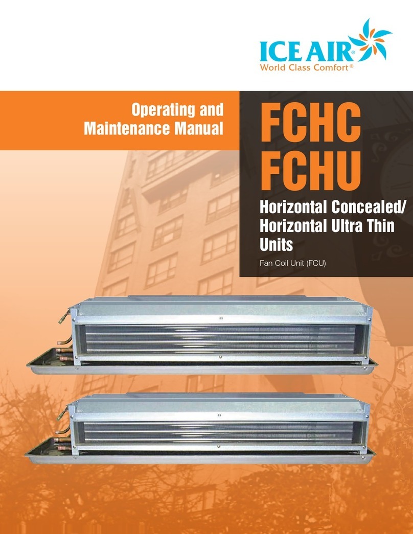
ICE AIR FCHC User manual

Precautions and preparations listed are for general knowledge and to define basic guidelines. Local codes and existing practices should be observed and preformed by a professional.
Due to ICE AIRs ongoing product development programs, the information in this document is subject to change without notice.
Installation Manual FCHC
FCHU
Horizontal Concealed/
Horizontal Ultra Thin
Units
Fan Coil Unit (FCU)

Precautions and preparations listed are for general knowledge and to define basic guidelines. Local codes and existing practices should be observed and preformed by a professional.
Due to ICE AIRs ongoing product development programs, the information in this document is subject to change without notice.
Thank you for purchasing and installing the ICE AIR FCU (Fan Coil
Unit). ICE AIR is a leading supplier of FCUs, offering superior quality,
reliability and efficiency for our customers.
ATTENTION INSTALLING PROFESSIONAL
Read this manual and familiarize yourself with the specific terms and
safety warnings that must be adhered to before attempting to install
or service this unit. Precautions listed are intended as supplemental
to existing practices. As a professional, you have an obligation to
know the product better than the customer. This includes all safety
precautions and related items. It is your responsibility to install the
product safely and know it well enough to be able to instruct a
customer in its safe use as required.
p
! RECOGNIZE THIS SYMBOL AS A SAFETY PRECAUTION.
p
!WARNING: ICE AIR will not be responsible for any injury or
property damage arising from improper service or service
procedures. If you install or perform service on this unit, you
assume responsibility for any personal injury or property
damage which may result. Many jurisdictions require a license
to install or service heating and air conditioning equipment.
p
!WARNING, HIGH VOLTAGE: Disconnect all power before
servicing or installing unit. Multiple power sources may be
present. Failure to do so may cause property damage, personal
injury or death.
To ensure that the unit operates safely and efficiently, it must be
installed according to these installation instructions and all local
codes and ordinances, utilizing the best standards and practices at
the time of installation or, in their absence, with the latest edition
of the National Electric Code. The proper installation of this unit is
described in the following sections. Following the steps in the order
presented should ensure proper installation.
Contents
General/Safety Information.......................... 2
Overview/Application Note/Prerequisite ..... 3
FCHC Nomenclature...................................... 4
FCHC Valve Package Nomenclature............. 5
FCHU Nomenclature...................................... 6
FCHU Valve Package Nomenclature............. 7
Before You Begin .......................................... 8
Installation.................................................... 9
Filter Installation/Replacement.................... 9
Piping Installation ....................................... 9
General Electric .....................................10-11
Line Voltage.............................................. 10
General Line Voltage Wiring ...................... 10
Power Connection..................................... 10
System Cleaning and Flushing................... 12
Troubleshooting .......................................... 13
System Check List ...................................... 14
Warranty/Contact Information ................... 15
2

Precautions and preparations listed are for general knowledge and to define basic guidelines. Local codes and existing practices should be observed and preformed by a professional.
Due to ICE AIRs ongoing product development programs, the information in this document is subject to change without notice.
Overview
Installing the ICE AIR Horizontal FCU’s
involves two main components and various
accessory components.
Application Note
It is important for heating/cooling systems
to be properly sized for each application in
order to achieve desired temperature and
humidity levels. It is highly recommended
that a professional engineer match the FCU
you are about to install with the building
structure and climate.
Prerequisite
1. Locate the unit where it can evenly
distribute air throughout the room
without obstructions. Units should be
installed no closer than 18” apart when
two units are side by side. A vertical
clearance of 60” should be maintained
between units.
2. Adequate ceiling panel access must
exist for hanger brackets, duct collars
and fittings at water and electrical
connections
3. A minimum obstructed distance of 36”
should be kept around the unit.
4. Adequate and continuous water flow
must be maintained for proper and
safe unit operation. Ensure adequate
drainage is also available.
5. Dedicated electrical circuitry and power
supply is required to properly energize
the ICE AIR unit. Verify the amperage of
the dedicated electrical service to the
unit is correct and the unit can reach the
power supply.
6. Please ensure the unit meets the
guidelines of National Fire Protection
Association (N.F.P.A.) Standard 90A or
90B regarding concealed units.
JUNCTION BOX
ISOMETRIC VIEW
(FRONT-LEFT)
ISOMETRIC VIEW
(FRONT-RIGHT)
DUCT COLLAR
CONDENSATE DRAIN
CHILLED/HOT WATER
SUPPLY AND RETURN
CONNECTIONS
MOUNTING HOLES
AIR SUPPLY
3

Precautions and preparations listed are for general knowledge and to define basic guidelines. Local codes and existing practices should be observed and preformed by a professional.
Due to ICE AIRs ongoing product development programs, the information in this document is subject to change without notice.
Item 1 8Voltage 5- 115V - 1Ph - 60Hz 8- 208V - 1Ph - 60Hz 7- 277V - 1Ph - 60Hz
Item 2 FCHC Unit FCHC
Item 3 08 CFM 02- 200 03- 300 04- 400 06- 600 08- 800 10- 1000 12- 1200
Item 4 EMotors P- PSC S- PSC Hi Static E- ECM
Item 5 MPiping A- RH 2 Pipe Heat and Cool MCO
B- RH 2 Pipe Heat and Cool w/Aux Electric Heat MCO
C- RH 2 Pipe Heat and Cool w/Aux Electric Heat ACO
D- RH 2 Pipe Cool w/Total Elec Heat MCO
E- RH 2 Pipe Cool w/Total Elec Heat ACO
F- RH 2 Pipe Heat Only
G- LH 2 Pipe Heat and Cool MCO
H- LH 2 Pipe Heat and Cool w/Aux Electric Heat MCO
I- LH 2 Pipe Heat and Cool w/Aux Electric Heat ACO
J- LH 2 Pipe Cool w/Total Elec Heat MCO
K- LH 2 Pipe Cool w/Total Elec Heat ACO
L- LH 2 Pipe Heat Only
M- RH 4 Pipe Heat and Cool MCO
N- RH 4 Pipe Heat and Cool ACO
O- LH 4 Pipe Heat and Cool MCO
P- LH 4 Pipe Heat and Cool ACO
Item 6 XEnclosure X- Not applicable
Item 7 XPlenums B- Bottom Return R- Rear Return F- Front Return X- No Plenum
Item 8 6Controls 1- Unit Mounted Fan Mode Switch
2- Wall Mounted Fan Mode Switch
3- Unit Mounted Fan Mode Switch and Manual (Knob) Thermostat
4- Touchpad non programmable thermostat
5- LCD Non programmable thermostat
6- LCD programmable thermostat
7- Wired for ELA11599 Non Programmable Thermostat
8- Wired for ELA11599 Programmable Thermostat
9- 24V Terminal for external controls by others
Item 9 2Coil Rows 2- 2 3- 3 4- 4
Item 10 BCoil Orientation B- 1 Cool, 1 Heat
Item 11 SDrain Pan G- Galvanized Powder Coated (Black) S- Stainless Steel
Item 12 XDisconnect Switch F- Fused N- Non Fused X- None
FCHC Nomenclature
Model Selection 8 FCHC 08 - E M X X 6 2 B S X - 1 A G A X 1 P P M F S
Item Number 1 2 3 4 5 6 7 8 9 10 11 12 13 14 15 16 17 18 19 20 21 22 23
Primary Part Secondary Parts Valve Package Parts
4

Precautions and preparations listed are for general knowledge and to define basic guidelines. Local codes and existing practices should be observed and preformed by a professional.
Due to ICE AIRs ongoing product development programs, the information in this document is subject to change without notice.
Model Selection 8 FCHC 08 - E M X X 6 2 A S X - 22 A G A X 1 P P M F S
Item Number 1 2 3 4 5 6 7 8 9 10 11 12 13 14 15 16 17 18 19 20 21 22 23
Primary Part Secondary Parts Valve Package Parts
FCHC Valve Package Nomenclature
Item 13 22 Motorized Valve
Package
22- Line Voltage 2 Way MV* Heat NO, Cool NO
23- Line Voltage 2 Way MV* Heat NC, Cool NO
24- Line Voltage 2 Way MV* Heat NO, Cool NC
25- Line Voltage 2 Way MV* Heat NC, Cool NC
26- Line Voltage 3 Way MV* #1 NO Diverting,
#2 NO Diverting
27- Line Voltage 3 Way MV* #1 NC Diverting,
#2 NO Diverting
28- Line Voltage 3 Way MV* #1 NC Diverting,
#2 NC Diverting
29- 24V 2 Way MV* Heat NO, Cool NO
30-24V 2 Way MV* Heat NC, Cool NO
31- 24V 2 Way MV* Heat NO, Cool NC
32- 24V 2 Way MV* Heat NC, Cool NC
33- 24V 3 Way MV* #1 NO Diverting,
#2 NO Diverting
34- 24V 3 Way MV* #1 NC Diverting,
#2 NO Diverting
35- 24V 3 Way MV* #1 NC Diverting,
#2 NC Diverting
X- None
Item 14 AElectric Heat A- 1 B- 1.5 C- 2 D- 3 E- 3.5 F- 4.3 G- 5 H- 6 I- 7.5
J- 10 X- No Electric Heat
Item 15 GSecondary Drain
Pan
G- Galvanized Powder Coated (Custom Color) S- Stainless Steel X- None
Item 16 AFlow Regulation
Cooling Coil
A- Balancing Valve B- Circuit Setter C- Autoflow Valve 0.5 GPM
D- Autoflow Valve 1.0 GPM E- Autoflow Valve 1.3 GPM F- Autoflow Valve 1.5 GPM
G- Autoflow Valve 2.0 GPM H- Autoflow Valve 2.5 GPM I- Autoflow Valve 2.8 GPM
J- Autoflow Valve 3.0 GPM K- Autoflow Valve 3.3 GPM L- Autoflow Valve 3.5 GPM
M- Autoflow Valve 4.0 GPM N- Autoflow Valve 4.5 GPM O- Autoflow Valve 5.0 GPM
P- Autoflow Valve 5.5 GPM Q- Autoflow Valve 6.0 GPM R- Autoflow Valve 6.5 GPM
S- Autoflow Valve 7.0 GPM T- Autoflow Valve 7.5 GPM U- Autoflow Valve 8.0 GPM
V- Autoflow Valve 8.5 GPM W- Autoflow Valve 9.0 GPM X- None
Item 17 XFlow Regulation
Heating Coil
A- Balancing Valve B- Circuit Setter C- Autoflow Valve 0.5 GPM
D- Autoflow Valve 1.0 GPM E- Autoflow Valve 1.3 GPM F- Autoflow Valve 1.5 GPM
G- Autoflow Valve 2.0 GPM H- Autoflow Valve 2.5 GPM I- Autoflow Valve 2.8 GPM
J- Autoflow Valve 3.0 GPM K- Autoflow Valve 3.3 GPM L- Autoflow Valve 3.5 GPM
M- Autoflow Valve 4.0 GPM N- Autoflow Valve 4.5 GPM O- Autoflow Valve 5.0 GPM
P- Autoflow Valve 5.5 GPM Q- Autoflow Valve 6.0 GPM R- Autoflow Valve 6.5 GPM
S- Autoflow Valve 7.0 GPM T- Autoflow Valve 7.5 GPM U- Autoflow Valve 8.0 GPM
V- Autoflow Valve 8.5 GPM W- Autoflow Valve 9.0 GPM X- None
Item 18 1Y-Strainer 1- Y-Strainer 2- Y-Strainer Blow Down X- None
Item 19 PPurge Valve P- Yes X-No
Item 20 PPT Ports P- Yes X-No
Item 21 MAir Vents M- Manual A- Automatic X- None
Item 22 FCondensate
Overflow Switch
F- Float E- Electronic X- None
Item 23 SPipe Connections S- Sweat M- Male NPT F- Female NPT U- Unions
* MV = Motorized Valve
5

Precautions and preparations listed are for general knowledge and to define basic guidelines. Local codes and existing practices should be observed and preformed by a professional.
Due to ICE AIRs ongoing product development programs, the information in this document is subject to change without notice.
Item1 8Voltage 5- 115V - 1Ph - 60Hz 8- 208V - 1Ph - 60Hz 7- 277V - 1Ph - 60Hz
Item 2 FCHU Unit FCHU
Item 3 06 CFM 02- 200 03- 300 04- 400 06- 600
Item 4 EMotors P- PSC S- PSC Hi Static E- ECM
Item 5 MPiping A- RH 2 Pipe Heat and Cool MCO
B- RH 2 Pipe Heat and Cool w/Aux Electric Heat MCO
C- RH 2 Pipe Heat and Cool w/Aux Electric Heat ACO
D- RH 2 Pipe Cool w/Total Elec Heat MCO
E- RH 2 Pipe Cool w/Total Elec Heat ACO
F- RH 2 Pipe Heat Only
G- LH 2 Pipe Heat and Cool MCO
H- LH 2 Pipe Heat and Cool w/Aux Electric Heat MCO
I- LH 2 Pipe Heat and Cool w/Aux Electric Heat ACO
J- LH 2 Pipe Cool w/Total Elec Heat MCO
K- LH 2 Pipe Cool w/Total Elec Heat ACO
L- LH 2 Pipe Heat Only
M- RH 4 Pipe Heat and Cool MCO
N- RH 4 Pipe Heat and Cool ACO
O- LH 4 Pipe Heat and Cool MCO
P- LH 4 Pipe Heat and Cool ACO
Item 6 XEnclosure X- Not applicable
Item 7 XPlenums B- Bottom Return R- Rear Return F- Front Return X- No Plenum
Item 8 6Controls 1- Unit Mounted Fan Mode Switch
2- Wall Mounted Fan Mode Switch
3- Unit Mounted Fan Mode Switch and Manual (Knob) Thermostat
4- Touchpad non programmable thermostat
5- LCD Non programmable thermostat
6- LCD programmable thermostat
7- Wired for ELA11599 Non Programmable Thermostat
8- Wired for ELA11599 Programmable Thermostat
9- 24V Terminal for external controls by others
Item 9 2Coil Rows 2- 2 3- 3 4- 4
Item 10 ACoil Orientation A- Dedicated Cool or Heat
Item 11 SDrain Pan G- Galvanized Powder Coated (Black) S- Stainless Steel
Item 12 XDisconnect Switch F- Fused N- Non Fused X- None
FCHU Nomenclature
Model Selection 8 FCHU 06 - E M X X 6 2 A S X - 22 A G A A 1 P P M F S
Item Number 1 2 3 4 5 6 7 8 9 10 11 12 13 14 15 16 17 18 19 20 21 22 23
Primary Part Secondary Parts Valve Package Parts
6

Precautions and preparations listed are for general knowledge and to define basic guidelines. Local codes and existing practices should be observed and preformed by a professional.
Due to ICE AIRs ongoing product development programs, the information in this document is subject to change without notice.
Model Selection 8 FCHU 08 - E M X X 6 2 B S X - 01 A G A X 1 P P M F S
Item Number 1 2 3 4 5 6 7 8 9 10 11 12 13 14 15 16 17 18 19 20 21 22 23
Primary Part Secondary Parts Valve Package Parts
FCHU Valve Package Nomenclature
Item 13 01 Motorized Valve
Package
01- Line Voltage 2 Way MV* Normally Closed
02- Line Voltage 2 Way MV* Normally Open
03- Line Voltage 3 Way MV* Normally Closed
Routing
04- Line Voltage 3 Way MV* Normally Closed
Diverting
05- Line Voltage 3 Way MV* Normally Open
Routing
06- Line Voltage 3 Way MV* Normally Open
Diverting
07- Line Voltage 3 Way MV* Normally Closed
Routing w/ Bypass Pipe
08- Line Voltage 3 Way MV* Normally Closed
Diverting w/ Bypass Pipe
09- Line Voltage 3 Way MV* Normally Open
Routing w/ Bypass Pipe
10- Line Voltage 3 Way MV* Normally Open
Diverting w/ Bypass Pipe
11- 24V 2 Way MV* Normally Closed
12- 24V 2 Way MV* Normally Open
13- 24V 3 Way MV* Normally Closed Routing
14- 24V 3 Way MV* Normally Closed Diverting
15- 24V 3 Way MV* Normally Open Routing
16- 24V 3 Way MV* Normally Open Diverting
17- 24V 3 Way MV* Normally Closed Routing
w/ Bypass Pipe
18- 24V 3 Way MV* Normally Closed Diverting
w/ Bypass Pipe
19- 24V 3 Way MV* Normally Open Routing
w/ Bypass Pipe
20- 24V 3 Way MV* Normally Open Diverting
w/ Bypass Pipe
21- Wired for 24V MV* control - MV* by others
X- None
Item 14 AElectric Heat A- 1 B- 1.5 C- 2 D- 3 E- 3.5 F- 4.3 G- 5 H- 6 I- 7.5
J- 10 X- No Electric Heat
Item 15 GSecondary Drain
Pan
G- Galvanized Powder Coated (Custom Color) S- Stainless Steel X- None
Item 16 AFlow Regulation
Cooling Coil
A- Balancing Valve B- Circuit Setter C- Autoflow Valve 0.5 GPM
D- Autoflow Valve 1.0 GPM E- Autoflow Valve 1.3 GPM F- Autoflow Valve 1.5 GPM
G- Autoflow Valve 2.0 GPM H- Autoflow Valve 2.5 GPM I- Autoflow Valve 2.8 GPM
J- Autoflow Valve 3.0 GPM K- Autoflow Valve 3.3 GPM L- Autoflow Valve 3.5 GPM
M- Autoflow Valve 4.0 GPM N- Autoflow Valve 4.5 GPM O- Autoflow Valve 5.0 GPM
P- Autoflow Valve 5.5 GPM Q- Autoflow Valve 6.0 GPM R- Autoflow Valve 6.5 GPM
S- Autoflow Valve 7.0 GPM T- Autoflow Valve 7.5 GPM U- Autoflow Valve 8.0 GPM
V- Autoflow Valve 8.5 GPM W- Autoflow Valve 9.0 GPM X- None
Item 17 XFlow Regulation
Heating Coil
X- Not Applicable
Item 18 1Y-Strainer 1- Y-Strainer 2- Y-Strainer Blow Down X- None
Item 19 PPurge Valve P- Yes X-No
Item 20 PPT Ports P- Yes X-No
Item 21 MAir Vents M- Manual A- Automatic X- None
Item 22 FCondensate
Overflow Switch
F- Float E- Electronic X- None
Item 23 SPipe Connections S- Sweat M- Male NPT F- Female NPT U- Unions
* MV = Motorized Valve
7

Precautions and preparations listed are for general knowledge and to define basic guidelines. Local codes and existing practices should be observed and preformed by a professional.
Due to ICE AIRs ongoing product development programs, the information in this document is subject to change without notice.
Before You Begin
1. Locate the unit where it can evenly
distribute air throughout the room
without obstructions. Units should be
installed no closer than 12” apart when
two units are side by side. A vertical
clearance of 60” should be maintained
between units.
2. Ensure the wall is structurally sound to
support the weight of the unit.
3. Ensure adequate drainage is available.
4. Follow all applicable codes for
installation.
5. Verify the amperage of the dedicated
electrical service to the unit is correct
and the unit can reach the power supply.
6. Position the unit so the air filter can
be removed easily and required
maintenance can be performed without
interference.
7. A minimum obstructed distance of 36”
should be kept around theunit.
IMPORTANT: To avoid permanent damage to
the unit, DO NOT operate during construction
in an open space or as a supplemental
heating and cooling source during
construction.
Inspection
1. Upon receipt of the equipment, carefully
check the shipment again on the Bill of
Lading.
2. Make sure all units have been received.
3. Inspect the packaging for any damage.
4. Ensure that any damage is noted on the
delivering carriers Bill of Lading.
NOTE: It is the responsibility of the purchaser
to file all necessary claims with the delivering
carrier in a timely fashion. Many carriers
have a 15 day notice period from receipt of
delivery to file any and all claims.
TOP VIEW
A
B
LEFT VIEW
FRONT VIEW
RIGHT VIEW
9"
9 1/4
"
RIGHT VIEW
A
TOP VIEW
9"
FRONT VIEW
CHILLED / HOT WATER SUPPLY
& RETURN CONNECTIONS
5/8" O.D.
OPTIONAL DRIP LIP
SHIPPED LOOSE
RESILIENT MOUNTING GROMMET
W/ 3/8" DIA. HOLES (TYP. OF 4)
7/8" O.D.
CONDENSATE
DRAIN
FLEXIBLE METAL CONDUIT
JUNCTION BOX (REMOTE MOUNT)
B
MTG. HOLES
C
FCHC02 FCHC03 FCHC04 FCHC06 FCHC08 FCHC10 FCHC12
“A” Width
“B” Height
“C” Depth
30”
9”
19-1/2”
30”
9”
19-1/2”
41-3/4”
9”
19-1/2”
45-1/4”
9”
19-1/2”
59-1/2”
9”
19-1/2”
59-1/2”
9”
19-1/2”
67-3/4”
9”
19-1/2”
FCHU02 FCHU03 FCHU04 FCHU06
“A” Width
“B” Height
“C” Depth
30”
8”
18-5/8”
30”
8”
18-5/8”
41-3/4”
8”
18-5/8”
45-1/4”
8”
18-5/8”
B
C
TOP VIEW
FRONT VIEW
RIGHT SIDE VIEW
A
Horizontal Concealed
Horizontal Ultra Thin
8

Precautions and preparations listed are for general knowledge and to define basic guidelines. Local codes and existing practices should be observed and preformed by a professional.
Due to ICE AIRs ongoing product development programs, the information in this document is subject to change without notice.
Installation
Installing the Unit
1. Ensure all preparations are met within
the “Pre-Requisite Section.”
2. Within the concealed ceiling, mark the
position of where threaded rods will
attach to. Refer to the submittal for
specific dimensions.
3 Embed four (4) threaded rods into the
indicated positions. Ensure the ceiling is
structurally intact to support weight of
the unit.
Refer to
table at right
for specific
weights.
4. Connect the
ICE AIR unit to
the threaded
rods through
the four (4) brackets on each corner.
Attach a Vibrational Isolator beneath the
bracket and a washer below that. Latch
these pieces in place with a hex nut.
Dual hex nuts are recommended as a
precautionary measure (see below).
5. Ensure the discharge vent is level,
elsewise adjust the threaded rods to
correct the unit. WARNING: Do not
loosen the nuts, this will increase the
chance of vibrational failure.
6. Attach all necessary pipes and wiring
connections. Additional ductwork should
only be installed if instructed.
7. (RECESSED) Fasten the Access Panel
to the bottom of the unit and tighten to
the unit. Ensure the open panel is not
fastened.
8. Run the unit.
Piping Installation
ICE AIRs Horizontal Concealed Fan Coil
is available in either 2 pipe or 4 pipe
configurations (see below) that are
connected to the system through the use
of a flexible hose or rigid pipe. The piping
system should be flushed to remove dirt,
pipe shavings, chips and other foreign
material prior to operation (refer to System
Cleaning and Flushing section). The flow rate
is generally set between 2 and 3 GPM per
ton of cooling for most applications of water
loop fan coils. To ensure proper maintenance
and servicing, P/T ports are imperative for
temperature and flow verification, as well as
performance checks.
Ducting Installation
If the system calls for ducting, attach the
duct to the duct collar on the supply vent. To
secure the duct, fasten to collar until there is
no exposed airflow (See below).
Filter Installation
Only configurations with a plenum on the
return vent for the Horizontal Concealed
Fan Coil are delivered with a filter. Filters
are placed on the bottom slot and pressed
forward into place.
Filter Replacement
The ICE AIR unit is delivered with a
Dispensable Filter. Dispensable Filters should
be replaced twice every year, before the start
of every heating or cooling season. Please
contact your local sales representative for
replacements.
2 Pipe
Configuration
4 Pipe Configuration
Bracket
Vibration
Isolator
Washer
Hex Nut
Threaded
Rod
Threaded
Rod Detail
DUCT
COLLAR
FCHC/FCHU Weight Table
Gross Net
Unit lbs. kg. lbs. kg.
02 30 13.5 25 11
03 31 14 26.5 12
04 40 18 37.5 17
06 45 20.5 41 18.5
08 53 24 46 21
10 60 27 50.5 23
12 64 29 54 24.5
FILTER SHOWN INSTALLED
9

Precautions and preparations listed are for general knowledge and to define basic guidelines. Local codes and existing practices should be observed and preformed by a professional.
Due to ICE AIRs ongoing product development programs, the information in this document is subject to change without notice.
Room Temp ProbeL N
Optional
WHT
V
WHTRED
HTG
BRN
BLK
CLG
Auto Change Over
YELWHT
WHT
BRN
C
BRN
Fan
Motor
BLU
GRD
N
Circuit #1
To Low Voltage
Thermostat
Transformer
ELA-8693/ELA-8694
Relay Board
Notes:
1. Some components on legend are no
t
used on all schematics.
2. Cap off unused wire on fan motor
when present.
Component Outline
Field Wiring
Factory Wiring
Wire Color
Wire Connector
Field Connector
CLG
HTG
C
SI
V
Legend:
BLK
CAP
Front
3 2 1
6 5 4
9 8 7
12 11 10
1 2 3
4 5 6
7 8 9
10 11 12
Mount
Guide
Wiring
Guide
Back
COM
NO
RED
BLU
BLK
LOW
HI
MED
1 2 3
4 5 6
7 8 9
10 11 12
P2
P1
CON1
R
C
COOL
F1
F2
F3
H1
H2
P
G
RT
F1
F2
F3
HEAT1
HEAT2
Cooling
Heating
Capacitor
3 Speed Switch
Valve
Wire Chart
1BLK Common
2RED 24VAC
3 YEL Cooling
4 WHT Heat
5—Not in Use —
6GRN Lo-Cool
7BLU Me-Cool
8—Not in Use —
9 ORN Hi-Cool
10 GRY Room Temp
11 PUR G
12 BRN Pipe Sensor
2 Pipe System
General Electric
Line Voltage
Wiring, including the electrical ground, must comply with the National
Electrical Code as well as all applicable local codes. Refer to the
Electrical Data table for fuse sizes. Consult the wiring diagram below
for field connections on the right of the electrical diagram located on
the back of the unit electrical compartment front panel. All electrical
connections must be made by the installing (or electrical) contractor.
All final electrical connections must be made with a length of flexible
conduit to minimize vibration and sound transmission to the building.
p
!WARNING: Electrical shock can cause personal injury or death
while installing or servicing the system. Always turn OFF the
main power to system. There may be more than one
disconnect switch.
General Line Voltage Wiring
Be sure the available power is the same voltage and phase shown
on the unit serial number plate. Line and low voltage wiring must be
done in accordance with local codes or the National Electric Code,
whichever is applicable.
Power Connection
Units equipped with disconnect: Connect incoming line voltage
to the disconnect switch and connect ground wire to the ground lug
provided inside the electrical compartment.
Units without disconnect: Line voltage connection is made by
connecting the incoming line voltage wires to the terminal block.
10

Precautions and preparations listed are for general knowledge and to define basic guidelines. Local codes and existing practices should be observed and preformed by a professional.
Due to ICE AIRs ongoing product development programs, the information in this document is subject to change without notice.
4 Pipe System
Room Temp ProbeL N
YELWHT
WHT
BRN
C
BRN
Fan
Motor
BLU
GRD
N
Circuit #1
To Low Voltage
Thermostat
Transformer
ELA-8693/ELA-8694
Relay Board
Notes:
1. Some components on legend are not
used on all schematics.
2. Cap off unused wire on fan motor
when present.
Component Outline
Field Wiring
Factory Wiring
Wire Color
Wire Connector
Field Connector
CLG
HTG
C
SI
V
Legend:
BLK
CAP
Front
3 2 1
6 5 4
9 8 7
12 11 10
1 2 3
4 5 6
7 8 9
10 11 12
Mount
Guide
Wiring
Guide
Back
COM
NO
RED
BLU
BLK
LOW
HI
MED
1 2 3
4 5 6
7 8 9
10 11 12
P2
P1
CON1
R
C
COOL
F1
F2
F3
H1
H2
P
G
RT
F1
F2
F3
HEAT1
HEAT2
Cooling
Heating
Capacitor
3 Speed Switch
Valve
Wire Chart
1BLK Common
2RED 24VAC
3 YEL Cooling
4 WHT Heat
5—Not in Use —
6GRN Lo-Cool
7BLU Me-Cool
8—Not in Use —
9 ORN Hi-Cool
10 GRY Room Temp
11 PUR G
12 BRN Pipe Sensor
Optional
WHT
V
WHT
HTG
BRN
BLK
CLG
WHTV
Evaporator speeds configuration
Cooling – HI or MED
Heating – MED or LOW
2 1 3 6 7 9 4 12 11 10
R C
COOL
F1 F2 F3 H1 P G KT
1 2 3 4 5 6 7
11

Precautions and preparations listed are for general knowledge and to define basic guidelines. Local codes and existing practices should be observed and preformed by a professional.
Due to ICE AIRs ongoing product development programs, the information in this document is subject to change without notice.
System Cleaning and Flushing
Cleaning and flushing the unit is the most important step to ensure
proper start-up and continued efficient operation of the system.
Follow the instructions below to properly clean and flush the system:
1. Verify that electrical power to the unit is OFF.
2. Verify that supply and return riser service valves are closed at
each unit.
3. Fill the system with water, leaving the air vents open. Bleed all air
from the system, but do not allow the system to over flow. Check
the system for leaks and make any required repairs.
4. Adjust the water and air level in the expansion tank.
5. With strainers in place, start the pumps. Systematically check
each vent to ensure that all of the air is bled from the system.
6. Verify that make-up water is available and adjusted to properly
replace any space remaining when all air is purged. Check the
system for leaks and make any additional repairs if needed.
7. Set the boiler to raise the loop temperature to approximately
85°F (29.4°C). Open the drain at the lowest point in the system.
Verify that make-up water replacement rate equals rate of bleed.
Continue to bleed the system until the water appears clean or for
at least three hours, whichever is longer.
8. Completely drain the system.
12

Precautions and preparations listed are for general knowledge and to define basic guidelines. Local codes and existing practices should be observed and preformed by a professional.
Due to ICE AIRs ongoing product development programs, the information in this document is subject to change without notice.
If unit is not operating, conduct the following checks:
1. Check the electrical connections.
2. Check the voltage and current against the electrical
specifications on the unit nameplate.
3. Look for wiring errors. Check for loose screw connections in both
line and low voltage terminals.
4. Check the water supply piping for proper water connection.
5. Check for dirty filters.
6. Check indoor fan for proper operation.
7. Check that unit did not cycle off due to improper thermostat
settings.
8. Check for fault codes on the control board – consult the Board
Troubleshooting Table.
Troubleshooting
IMPORTANT: It is not the intent of this maintenance manual to
resolve any problems with the operation of your ICE AIR unit.
Please contact a trained servicer or building maintenance
staff immediately if your unit fails to perform properly.
1. Contact a trained service technician to conduct full unit
diagnostics and repair to equipment.
2. Record any unit that does not operate noting the unit serial
number on your report.
p
! RECOGNIZE THIS SYMBOL AS A SAFETY PRECAUTION.
p
!WARNING: ICE AIR will not be responsible for any injury or
property damage arising from improper service or service
procedures. If you install or perform service on this unit, you
assume responsibility for any personal injury or property
damage which may result. Many jurisdictions require a license
to install or service heating and air conditioning equipment.
p
!WARNING HIGH VOLTAGE: Disconnect all power before
servicing or installing unit. Multiple power sources may be
present. Failure to do so may cause property damage,
personal injury or death.
13

Precautions and preparations listed are for general knowledge and to define basic guidelines. Local codes and existing practices should be observed and preformed by a professional.
Due to ICE AIRs ongoing product development programs, the information in this document is subject to change without notice.
System Check List
Installer: Complete unit and system checkout and follow unit start-up procedures provided with the unit. Use this form to record information,
temperatures and pressures during start-up. Keep this form for future reference.
Location Information.
Owner:
Address:
Model Number:
Serial Number:
Unit Location in Building:
Date:
Sales Order No:
In order to minimize troubleshooting and costly system failures,
complete the following checks and data entries before the system is
put into full operation.
Temperatures: (Circle) F or C
Antifreeze: __________Type: __________%
Pressures: (Circle) PSIG or kPa
Allow unit to run 15 minutes in each mode before taking data.
Do not connect service manifold gauges during start up unless
instructed by ICE AIR service tech.
Cooling Mode Heating
Mode
Return-Air Temperature DB (°F)
Supply-Air Temperature DB (°F)
Temperature Differential
Entering Fluid Temperature (°F)
Leaving Fluid Temperature (°F)
Temperature Differential
Water Pressure IN
Water Pressure OUT (PSI)
Pressure Differential (PSI)
Flow Rate (GPM)
Supply Voltage at Contactor (V)
Transformer Low Side Volts (V)
Compressor Amps (A)
Motor Amps (A)
14

Precautions and preparations listed are for general knowledge and to define basic guidelines. Local codes and existing practices should be observed and preformed by a professional.
Due to ICE AIRs ongoing product development programs, the information in this document is subject to change without notice.
Twelve (12) Month Warranty of ICE AIR units – ICE AIR,
LLC, herein referred to as “ICE AIR,” warrants to the
original owner that the entire unit is free from defects
in material and workmanship for a period of twelve (12)
months from the date of delivery. Any part of portion
thereof which becomes defective under normal use
during the period of this warranty will be repaired or
replaced provided ICE AIRs examination shall prove to its
satisfaction that the part was or became defective under
normal use. ICE AIRs obligations under this warranty
are limited to: (a) Repairing the defective part or (b)
furnishing a replacement part provided the defective
part is returned to the factory, without shipping damage,
transporting charges prepaid. No reimbursement will be
made for expenses incurred in making field adjustments
or replacements unless specifically authorized in writing
by the Company.
The Company is not obligated under this warranty for
field labor such as service for inspection, removing,
packing and/or reinstalling water source unit, nor for the
return transportation charges.
OPTIONAL Extended Refrigeration
Circuit Warranty
The Optional Extended Refrigeration Circuit Warranty
MUST be purchased from ICE AIR within thirty (30) days
from date of delivery to be valid. The hermetically sealed
refrigeration circuit (consisting of the motor, compressor
assembly, evaporator coil, coaxial/condenser coil and
interconnecting tubing) is warranted to the original
owner for four additional years from date of the
expiration of the Twelve Month Warranty. Components
under this warranty will be supplied at ICE AIRs expense
provided the failed component is returned to the factory.
This optional warranty does not include any other parts
of the equipment such as fans, fan motors, controls,
cabinet parts, electrical relays, capacitors, protective
devices, or wiring. ICE AIR is not obligated under this
warranty for field labor such as service for inspection,
removing, packing, and/or reinstalling the refrigeration
circuit, nor for return transportation charges. ICE AIR
reserves the right to make a handling and inspection
charge in the case of parts or equipment improperly
returned as defective and/or as being in warranty.
To obtain assistance under the parts warranty or to
purchase the optional extended warranty, simply contact
ICE AIR Customer Service at 80 Hartford Avenue, Mount
Vernon, New York 10553. Telephone 914-668-4700.
The Twelve Month and the OPTIONAL Extended
Refrigeration Circuit Warranty (which must be purchased
separately) constitute the buyer’s sole remedy. They are
given in lieu of all other warranties. There is no implied
warranty of merchant-ability or fitness for a particular
purpose. In no event and under no circumstance
shall ICE AIR be liable for incidental or consequential
damages, whether the theory is breach of this or any
warranty, negligence, or strict tort.
No person (including any agent, salesman, dealer or
distributor) has authority to expand ICE AIRs obligation
beyond the terms of these express warranties, or to
state that the performance of the product is other than
that published by ICE AIR.
General Conditions
The above warranties are void if ICE AIRs equipment
has been damaged, misused, subjected to abnormal
use or service or its serial number has been altered,
defaced, or removed, or payment for the equipment is in
default. ICE AIR is not responsible for service to correct
conditions due to misapplication, improper installation,
inadequate wiring, incorrect voltage conditions or
unauthorized opening of the refrigeration circuit, nor for
consequential damages. In case ICE AIRs equipment
is installed in conjunction with cabinets, grills, louvers,
controls or other parts manufactured by others, these
warranties shall apply only to ICE AIRs manufactured
portion of the equipment. The conditions of the standard
warranty plan are effective for 18 months from TCO. ICE
AIR reserves the right to make a handling and inspection
charge in the case of parts or equipment improperly
returned as defective and/or as being warranty.
Important
The following are the responsibility of the user. They
are not manufacturing defects, and are therefore not
included in the warranty plan.
1) Failure of unit to operate satisfactorily due to
improper amount of air on evaporator coil or air
supply to air cooled condensers.
2) Damage to unit or unsatisfactorily operation due to
improper cleaning of evaporator coil or use of unit
in corrosive atmosphere locations such as chemical
plants, refineries, or salt spray areas.
3) Damage to unit from unsatisfactory operation due
to blown fuses, inadequate or interrupted electrical
service, use of improper electrical protective devices
or operation of unit on power supply other than
covered by nameplate rating of unit.
4) Damage due to failure to properly maintain unit.
5) Damage due to transportation or handling prior to and
during installation.
6) Damage due to accident or from alteration, improper
installation, tampering.
7) Filter cleaning or replacement.
8) Misapplication.
Check, Test and Start
Check, Test and Start of the air conditioners by an
experienced person is the responsibility of the installing
contractor. This consists of physically confronting each
unit operating in both heating and cooling modes and
correcting any minor deficiencies noted. After the
equipment leaves the factory, it may become damaged
or maladjusted during transportation or on the job.
Sometimes wires are disconnected accidentally, or fan
motors move on their bases due to rough handling,
causing fans to strike; a component(s) may be
inoperable. The correction of such conditions is part of
the Check, Test and Start. Note that unless otherwise
specifically agreed to in writing, ICE AIR includes no field
labor, Check, Test, and Start (or the like) in the price of
its equipment.
Installation
ICE AIR is not responsible for the design, execution
and performance of the installation method or any of
the accessory items used during installation such as
seals, caulking, weatherproofing, supporting structures,
attachment means, louvers and frames supplied by
others.
80 Hartford Avenue, Mount Vernon, NY 10553
Tel: 877-ICE-AIR-1 (877-423-2471)
Fax: 914-668-5643
email: service@ice-air.com
www.ice-air.com
© 2017 by ICE AIR, LLC ICE6090 07/16
Limited Warranty
15
Other manuals for FCHC
1
This manual suits for next models
1
Table of contents
Other ICE AIR Fan manuals