Installation (Cont.)
5. Secure the unit in position, using three wood screws (No. 6).
Note: It may be necessary to drill and plug the mounting surface. It is
the responsibility of the installer to select the correct wall plug for the
particular application.
6. Fit the fan assembly to the case, securing it with the two spring clips.
Install the electronic control module ensuring that it is fully engaged in
the internal socket. If the pull-cord option is required it should be fed
through the aperture on the impeller housing before sliding the control
module into place. Fig. 5. (If the pullcord option is not required it
must be removed, see warning note on page 1).
7. Replace the front cover and secure using the two screws provided
(loose with filter and instructions). NOTE: Ensure the pull cord (if
fitted) passes through the slot in the base. (Fig. 5).
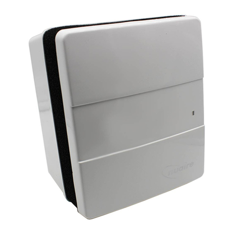
8. Fit the filter which is a push fit between the front cover and the body
of the unit (fig. 3).
9. Test run the unit noting that if a timer/humidistat option is fitted,
the unit may run-on for the duration of the control sequence.
Semi - recessed mounting
IMPORTANT NOTE Remove the shutters from the spigot if you are
mounting the genie in the ceiling.
1. Prepare an opening 184mm x 213mm. This will allow sufficient
clearance (approx. 5 to 10mm) all around the unit to accept the fixing
bracket (optional). Note. Do not exceed the quoted dimensions, as an
aperture larger than 208mm x 238mm will not be covered by the
finishing plate. Again it is assumed that a solid, non-reverberant
mounting position has been selected and the necessary passages for
ductwork from the outlet spigot as well as the electrical connection
prepared. It is also assumed that compatible ductwork is already
installed.
2. Position the mounting bracket (Fig. 7.) in the previously prepared
aperture so that the ends of the bracket are flush with the surface of the
wall. Secure the bracket with suitable fixings (by others) see Fig.8.
3. Remove the front cover /grille assembly (Refer to surface mounted
version for details).
4. Position the finishing plate on the base of the unit (fig 8). Place unit
base and finishing plate in the mounting bracket and feed the supply
cable through the casing aperture. Engage the outlet spigot in the duct-
work and fix the casing to the bracket using the screws supplied.
5. Connect the wiring to the internal terminal block / socket (it may be
easier to remove the block temporarily to facilitate wiring).
6. Fit fan module to the base
7. Fit the electronic control module, ensuring that it engages with the
internal socket. Note: If pullcord option is required, the cord should
now be fed through the aperture and into the small slot in the base.
see Fig.5. (If pullcord is not required it must be removed, see warning
note on page 1).
8. Replace the front cover with the two screws provided (loose with
filter and instructions) and refit the filter.
9. Test run the unit. Note! If a timer / humidistat option is fitted, the
unit may run on for the duration of the timer control sequence when
power is initially switched on.
Fig. 3. Removing / Replacing the front cover and filter.
Fig. 4. Electronic control module and Fan/Motor assembly
Fig. 5. Feeding the pull-cord through the housing.
2
