Ice-O-Matic RGA0501-HM User manual

Ice‐o‐Matic®
11100East45
th
Ave
Denver,Colorado80239
PartNumber9081487‐01Rev.K
INSTALLATION MANUAL REMOTE CONDENSERS
RCA1001, RCA1061,
RCA2061, RCA3061, RCA3561
RGA0501-HM, RGA1061-HM

Introduction
Ice-O-Matic® provides this manual as an aid to the service technician in installation and
maintenance of remote condensers. Do not attempt to perform installation, start-up or
maintenance unless you have read and fully understand this manual.
For a Service Provider, please reference our “Service and Support” tab at www.iceomatic.com
Keep this manual for future reference.
The Remote Condenser Service Parts Manuals are available separately.
Ice-O-Matic® icemakers and dispensers are not approved for outdoor installation.
WARNING: Always disconnect electrical power whenever maintenance or repairs are
performed on the remote condenser and related equipment.
CAUTION: Always wear protective eyewear whenever maintenance or repairs are
performed on the remote condenser and related equipment.
Ice-O-Matic® Warranty
Every Ice-O-Matic® remote condenser is backed by a warranty that provides both parts and
labor coverage. Ice-O-Matic® warranty registration should be filed online at
www.iceomatic/warranty

Freight Claims Procedure
Inspect Promptly
This merchandise has been carefully inspected and packed in accordance with the carrier’s
packing specifications. Responsibility for safe delivery has been assumed by the carrier. If loss
or damage occurs, you as the consignee must file a claim with the carrier and hold the container
for carrier’s inspection.
Visible Loss or Damage
Any external evidence of loss or damage must be fully described and noted on your freight bill
or express receipt and signed by the carrier’s agent. The claim should be filed on a form
available from the carrier.
Concealed Loss or Damage
If loss or damage does not appear until merchandise has been unpacked, make a written
request for inspection by the carrier within 5 days of the delivery date. Then file a claim on a
form from the carrier.
File Claim without Delay
Do Not Return Damaged Merchandise to Ice-O-Matic®

Table of Contents
General Information Page 1
Condenser and Ice Machine Pairing Page2
Installation Page 5
Remote Refrigeration System Page 7
Component Description Page 8
Electrical Connections Page 9
Condenser Leg Installation Page10
Refrigeration Tube Routing Page11/12
Coupling Instructions Page13

1
Condenser Dimensions (Inches)
Model Length Width Height Grill Kit Field Installed
RCA1001 30.85 30.85 37.01 GRILL10
RCA1061 30.85 30.85 37.01 GRILL10
RCA2061 30.85 30.85 41.79 GRILL20
RCA3061 30.85 30.85 37.10 GRILL30
RCA3561 30.85 30.85 41.79 GRILL20
RGA0501-HM* 30.85 30.85 37.01 GRILL10
RGA1061-HM* 30.85 30.85 37.01 GRILL10
*The RGA models DO NOT have a Mixing Valve in the condenser.
The RCA and RGA models DO NOT include side grills, they can be ordered as a Field Install
Kit, See Specific Model Number for Kit Part Number
Note the warning symbol where it appears in this manual. It is an alert for important safety
information on a hazard that might cause serious injury. Keep this manual for future
reference.
RCA Condenser
RGA Condenser

2
Condenser and Ice Machine Pairing
Remote Condenser Ice Machine Model
RCA1001 CIM0530R
RCA1061 CIM0535R, CIM0636R
RGA0501-HM* GEM0650R, MFI0800R
RGA1061-HM* GEM0956R, GEM1306R, MFI1256R, MFI1506R
*The RGA models DO NOT have a Mixing Valve in the condenser

3
Condenser and Ice Machine Pairing
Remote Condenser Ice Machine Model
RCA2061 CIM0825R, CIM0826R, CIM0835R,CIM0836R,CIM0837R,CIM1125R,
CIM1126R,CIM1135R, CIM1136R, CIM1137R, GEM2006R, MFI2306R,
CIM1446R, CIM1447R
RCA3561 CIM2046R, CIM2047R

4
Condenser and Ice Machine Pairing
Remote Condenser Ice Machine Model
RCA3061 CIM1845R, CIM1545R

5
Installation
Ice-O-Matic® Remote Condenser Systems are comprised of three components. The pre-charged remote
condenser, the pre-charged ice maker and the pre-charged line set. The pre-charged line sets are available
in 25, 40, or 75 foot line set lengths.
Note: The 75 foot line set will require adding an additional 28 ounces of refrigerant.
Normal installation of the ice maker should be followed. Reference the installation instructions included with
the ice maker. In any installation, the pre-charged line sets, consisting of a liquid line (3/8” dia.) and a
discharge line (1/2” dia.) are used as a one-time initial charge type installation.
Once the sealed couplings are connected and the internal seal is broken, the lines cannot be disconnected
without losing the refrigerant charge. They are, however, reusable and when the couplers are removed and
reconnected, the complete refrigeration system must be evacuated and re-charged with the proper amount
of refrigerant. Reference the ice maker data plate or ice maker service manual for proper refrigerant
charge.
General Description
The remote condenser should not be used in areas where sufficient airflow is not available, in the area the
ice maker is being installed, or the heat being rejected by the condenser coil will be undesirable.
The condenser coil should not be exposed to temperatures below -20F (-29C) or above 120F (49C).The
remote condenser functions as a normal refrigeration system until the temperature at the condenser coil
drops below 70F. At this time the mixing valve will begin to bypass enough hot gas from the discharge line
directly into the receiver to keep the liquid line feeding the expansion valve at a steady pressure. The
amount of gas bypassed will depend on the temperature at the condenser coil (the colder the temperature
at the condenser coil, the more gas will bypass and the tubing between the mixing valve and receiver will
become warmer).
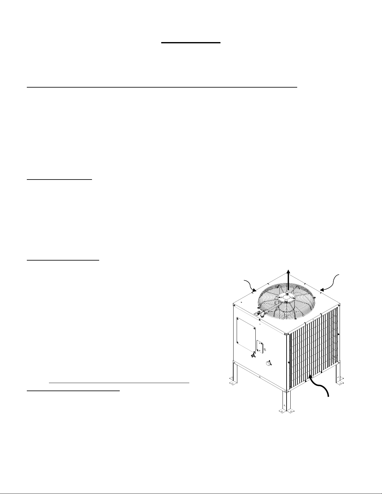
Condenser LocationWhen choosing a location for the remote condenser, reference the following
guidelines:
1. Choose a location that is protected from extremes of dirt,
dust, rain, sun and prevailing winds.
2. Vertical air discharge mounting of the condenser is
required with at least 48 inch clearance above the
condenser.
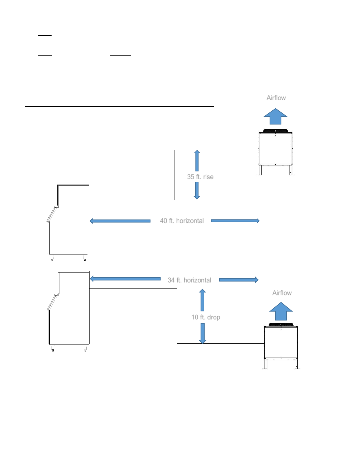
3. Condenser should be mounted higher than the ice
machine.
4. Condenser must be level.
5. Condenser should not be exposed to temperatures below
-20F or above 120F.
6. Installation must meet all local and national building,
plumbing and electrical codes.
7. The condenser must have a minimum clearance of
18 inches around all 4 sides.
8. Install condenser with the included legs or other elevated
mounting solution. There should be clearance between
the bottom of the condenser and the surface on which it is
mounted.
Airflow In
Airflow In
Airflow In
Airfl
o
w
Out

6
The RCA remote condensers incorporate the mixing valve in the condenser. This configuration allows up to
a 100 foot calculated remote line set run.
The RGA remote condensers Do Not have a mixing valve in the condenser.
Maximum Rise is 35 feet
Maximum Drop is 10 feet.
Maximum equivalent run is 100 feet.
Formula for calculating maximum equivalent run is as follows:
Rise x 1.7 + Drop x 6.6 + horizontal run = equivalent run
Example: 35 ft. rise x 1.7 + 40 ft. horizontal = 99.5 ft. equivalent line run
Example: 10 ft. drop x 6.6 + 34 ft. horizontal = 100 ft. equivalent line run
A
irflow
Airflow
35 ft. rise
40 ft. horizontal
10 ft. drop
34 ft. horizontal

7
REMOTE REFRIGERATION SYSTEM
The Remote Refrigeration System is shown in the above diagram. During the freezing cycle, high
temperature and high pressure liquid refrigerant is directed from the condenser through a mixing valve,
receiver, liquid line solenoid heat exchanger and a filter drier. The expansion valve meters refrigerant to the
coils on the back of the evaporator.
In low ambient conditions (below 70F air temperature at the condenser) the mixing valve opens to mix
discharge gas with liquid returning from the condenser, in the receiver, to maintain discharge and liquid line
pressures.
The low temperature and pressure refrigerant leaving the evaporator is directed through the suction line
heat exchanger and is returned to the compressor. There it is compressed to a high temperature and high
pressure gas. It is then directed to a condenser to be converted again to a high temperature and high
pressure liquid.
During the harvest cycle, the hot gas solenoid valve (normally closed during the freeze cycle), opens and
directs the high temperature gas leaving the compressor into the evaporator. Once the evaporator has
reached approximately 40F, the harvest motor overcomes the capillary attraction of the ice and the
evaporator releases the ice. At the end of the harvest cycle, the hot gas solenoid valve closes and another
freeze cycle begins.
During the off cycle, the liquid line solenoid valve closes.

8
Component Descriptions
Mixing Valve (Headmaster, Low Ambient Control Valve)
This valve serves as the head pressure regulating valve. It contains a pre-determined charge of nitrogen in
the valve bellows. When the temperature at the condenser is
above 70°F (21°C), the refrigerant flow from the compressor is
directed by the mixing valve through the condenser and into
the receiver. When the temperature at the condenser drops
below 70°F (21°C), the pressure in the bellows of the mixing
valve becomes greater than the pressure of the liquid
refrigerant coming from the condenser. This change allows
the valve to partially restrict the flow of refrigerant leaving the
condenser and allows discharge gas to by-pass the
condenser and flow directly into the receiver, mixing with the
liquid refrigerant from the condenser. The amount of
discharge gas that bypasses the condenser increases as the
ambient temperature decreases. This action of the mixing
valve allows the discharge pressure to be maintained at approximately 217 psi during low
ambient conditions. If the refrigerant system is undercharged and the ambient temperature is below 70°F
(21°C), the mixing valve will not work properly. The mixing valve will allow too much refrigerant to bypass
the condenser.
Receiver
The quantity of liquid refrigerant in the receiver will vary with the temperature at the condenser coil.
Liquid Line Solenoid and Pump Down Low Pressure Control
ICE Series ice machines
When the bin is full or the ON-OFF switch is turned to the OFF position, the liquid line
solenoid valve closes and the system begins to pump down. When the low pressure
reaches 10-20 psi, the pump down low pressure control opens and the contactor
shuts the machine off.
As the ice is removed from the bin or the ON-OFF switch is turned to the ON position, the liquid
line solenoid valve opens and the high side and low side pressures begin to equalize.
When the low side pressure reaches 50-75 psi, the pump down low pressure control closes and
the machine begins a freeze cycle. When the machine is off for extended periods of time, it will
pump down approximately once every hour. This is due to the equalization of pressures during
the off cycle resetting the pump down low pressure control. It is a normal function of the
refrigeration system.
CIM Series ice machines
When the bin is full or the machine is turned OFF, the machine will shut down 30 seconds after the pump
down initiation. The machine will pump down once every 2 hours, for 15 seconds during normal operation.
Condenser Fan Motor
The condenser fan motor is a single speed, permanent split capacitor motor and should be wired according
to the wiring diagram. The motor is permanently lubricated for long service life.

9
Electrical Connections
1. The icemaker and the remote condenser both require a solid earth ground that meets National,
State and Local Codes.
2. The Remote Condenser is designed to be wired to the Ice-O-Matic® ice maker.
3. Reference the ice machine and condenser date plate for current requirements to determine wire size
for electrical hook up.
4. Make sure the supply voltage is the same as the rated voltage shown on the nameplate.
5. Reference wiring diagram below for proper connections.
INSTALLATION NOTICE:
THE “RCA/RGA” SERIES REMOTE CONDENSERS MAY ONLY BE
USED WITH COMPATIBLE ICE-O-MATIC ICE MAKERS All Rack type
Condenser systems must receive prior approval from Ice-O-Matic®
Engineering.
Electrical shock and/or injury from moving parts inside this machine can cause serious injury.
Disconnect electrical supply voltage to the machine and condenser prior to performing any
adjustments or repairs.

10
Support Leg Installation
1. After removal of the packaging and fasteners, lift the condenser assembly off of the skid.
2. Locate the legs attached to the condenser assembly on the top panel. Remove the fastener holding
the legs to the top panel.
3. Assemble the legs to the condenser as shown below. Loosen the leg fastening nuts which are
preinstalled on the base studs. DO NOT remove the nuts. Slide the legs in position and retighten
the nuts.
Roof Attachment
1. Install and attach the remote condenser to the roof of the building using the methods and
practices of construction that conform to the local building codes, including having a roofing
contractor secure the remote condenser to the roof.
2. Have an electrician connect the remote condenser fan motor to the ice machine using the
junction box on the rear of the ice machine. Condenser shown with optional field
installed grills

11
Proper Tube Routing
When installing the discharge and liquid lines from the remote condenser to the icemaker, please use the
following guidelines:
1. The remote condenser (#2) should always be installed above the icemaker (#4) as shown with a
vertical air flow.
2. All excess tubing (#1) should be routed inside the building and coiled in a vertical spiral as shown
(#3), to prevent oil trapping in the lines. Any tubing run outside should be insulated to protect it from
surrounding ambient conditions. Tubing should follow straight line routing whenever possible. The
lowest spot in the tubing run should be the connection at the rear of the icemaker.
VerticalAirflow

12
Pre-charged Line Set Routing
CAUTION: Do not connect the pre-charged tubing until all routing and forming of the tubing is
complete. See the coupling instructions for connecting information.
1. Each set of pre-charged tubing refrigerant lines consists of a 3/8 diameter liquid line (#5) and a 1/2 inch
diameter discharge line (#6). Both ends of each line have quick connect couplings and Schrader valve
connections.
Note: The openings in the building ceiling or wall, listed in the next step, are the minimum sizes
recommended for passing the refrigerant lines through.
2. Have the roofing contractor cut a minimum hole for the refrigerant lines of 1.750 inch. Check local codes,
a separate hole may be required for the electrical power to the condenser.
CAUTION: DO NOT KINK OR CRIMP REFRIGERANT TUBING WHEN INSTALLING IT.
3. Route the refrigerant lines through the roof opening. Follow straight line routing whenever possible. Any
excess tubing MUST remain within the building.
4. Spiral the excess length of pre-charged tubing inside the building. Use a horizontal spiral (does not need
to be as tight as illustrated) to avoid any traps in the lines.
5. Have the roofing contractor seal the holes in the roof per local codes.
CAUTION: The couplings on the sets of pre-charged lines are self-sealing when installed properly.
Carefully follow the instructions:

13
Coupling Instructions:
Initial Connections:
1. Remove the protector caps and plugs. Wipe the seats and threaded surfaces with a clean cloth to be
certain that no foreign matter remains on them.
2. Lubricate the inside of the couplings, especially the O-Rings with refrigerant oil.
3. Position the fittings on the correct connections on the remote condenser
and ice machine.
●The 1/2 inch discharge line goes to the remote condenser fitting marked
“Discharge Line”
●The 3/8 inch liquid line goes to the remote condenser fitting marked
“Liquid Line”.
●The 1/2 inch discharge line goes to the ice machine fitting marked
“Discharge Line”.
●The 3/8 inch liquid line goes to the ice machine fitting marked
“Liquid Line”.
Final Connections:
4a. Begin by tightening the couplings together by hand. Continue to turn the swivel nuts by hand until it is
certain that the threads are properly engaged.
4b. Using two wrenches, one to rotate the swivel nut and one to hold the tubing, tighten each coupling.
It is CRITICAL that ONLY the NUT on the pre-charged tube be turned or
the diaphragms will be torn loose by the piercing knives and be loose in
the refrigeration system causing severe operational problems.
Note: As the coupling is tightened, the diaphragms in the quick connect
couplings will begin to be pierced. As that happens, there will be
increased resistance to tightening the swivel nut.
4c. Continue tightening the swivel until it bottoms out or a very definite
increase in resistance is felt (no threads should be showing). Do NOT over tighten.
5. Using a marker or pen, mark a line lengthwise from the coupling union nut
to the bulkhead. Then tighten the coupling and additional 1/4 turn. As
the nut turns, the line will show when the 1/4 turn is made.
6. After all connections are made, and after the king valve has been opened
(do not open at this time) check the couplings for leaks.

14
This manual suits for next models
6
Table of contents
Other Ice-O-Matic Heat Pump manuals
Popular Heat Pump manuals by other brands

Dimplex
Dimplex HPK 200S Installation and operating instructions

Blue Ridge
Blue Ridge BMKH12MCC owner's manual

Ferroli
Ferroli HXW LT Installation and operation manual

REMKO
REMKO RVT 264 DC Assembly and operating instructions

Zodiac
Zodiac Z250iQ Instructions for installation and use

Airwell
Airwell XLM9 Installation and maintenance manual