Icel Manaus MD-6540 User manual

MANUAL DE INSTRUÇÕES
DO MULTÍMETRO DIGITAL
MODELO MD-6540
(versão em Inglês)
Leia atentamente as
instruções contidas
neste manual antes de
iniciar o uso do
instrumento

TABLE OF CONTENTS
1. SAFETY 1
2. PRODUCT DESCRIPTION 2
3. PANELS OVERVIEW 4
3.1 REAR PANEL 5
4. BUTTONS FUNCTION 6
4.1 LIGHT (Yellow Button) 6
4..2 BAR 6
4.3 PEAK HOLD 7
4.4 AUTO HOLD 7
4.5BLUE 7
4.6 M/M/A 7
4.7REL △7
4.8 RANGE 7
4.9 dB/dBm 8
4.10STORE 8
4.11 RECALL 8
4.12 RED (Data Log) 8
4.12.1LOGRATE 8
4.12.2 DATALOG-IN 9
4.12.3DATALOG-OUT 9
4.12.4 ▲9
4.12.5 ▼9
4.13DTGIT 10
5. OPERATION 11
5.1 VOLTAGE MEASUREMENTS 11
5.2 Milli VOLTAGE MEASUREMENTS (AC,DC,AC + DC) 12
5.3 OHM AND LOW VOLTAGE OHM MEASUREMENTS 13
5.4DIODETEST 14
5.5 CONTINUITY CHECK 15
5.6 CURRENT MEASUREMENTS (AC, DC,AC + DC) 16
5.7 CAPACITANCE MEASUREMENTS 17
5.8 FREQUENCYAND DUTY FACTOR MEASUREMENTS 18
5.9 TEMPERATURE MEASUREMENTS 19
6. SPECIAL FEATURE DESCRIPTIONS 20
7. POWER-UP OPTIONS 20
8. SPECIFICATIONS 21
9. MAINTENANCE 28
10. ACCESSORIES 30

1. SAFETY
Review the following safety precautions to avoid injury and prevent damage to this product or
any products connected to it. To avoid potential hazards, use the
product only as specified.
#CAUTION. These statements identify conditions or practices that could
resultindamage to the equipment or other property.
#WARNING. These statements identify conditions or practices that could
resultinpersonalinjuryorlossoflife.
Symbols on the product
#Refer to manual 1Double Insulated "High Voltage
Specific precautions
Use proper Fuse. To avoid fire hazard, use only the fuse type and rating
specified for this product.
Do not operate without covers. To avoid personal injury , do not apply any voltage or current
to the product without the covers in place.
Electric overload. Never apply a voltage to a connector on the product that is outside the range
specified for that connector.
Avoid electric shock. To avoid injury or loss of life, do not connect or disconnect probes or test
leads while they are connected to a voltage source.
Do not operate in wet/damp conditions. To avoid electric shock , do not operate this product in
wet or damp conditions.

2. PRODUCT DESCRIPTION
The meters provide many functions and features, Depending on your meter type, each
type of meter has own features described in this manual.
The following list provides a comparison of the features between meters.
FUNCTION 107N 109N
DC Voltage ••
AC Voltage ••
mV Voltage ••
Resistance ••
Lo Ohm ••
Diode Test ••
Continuity Check ••
DC Current ••
AC Current ••
Capacitance ••
Frequency ••
Duty Factor ••
Temperature (K-Type) ••

FEATURES 107N
Auto Power Off (30 minutes) •
Analog Bargraph Display , 42 Segments Graph •
Center Zero Analog Bargraph •
Auto Calibration •
Auto HOLD •
Autorange With Rang HOLD •
Auto Fuse Detector •
Beep Guard •
dBm / dB Readings (600Ωfor dBm) •
Delta mode •
Hazard Warning •
Storage and Recell up to 1000 Memories •
Low Battery Indicator •
MAX / MIN /AVG •
Peak Hold (0.5ms) •
Data Log up to 40k memories 6K
True RMS (AC / DC + AC) •
VAC / Hz Dual Display •
Water / Dust Resistant •
Battery 9V
600V High Energy Fuse •
LCD Backlight •
Auto Backlight Off (15 Minutes) •
RS - 232 Phototronic Serial Port •
RS - 232 Cable Option
Win DMM 100 software Option
Holster and Stand •
Safety IEC, UL, CSA
CE Mark •

3. FRONT PANEL OVERVIEW
Figure 1
1. Input connectors.
2. Measurement function dial. Black labels are the initial settings, blue labels are
selected by the blue button.
3. Function buttons.
4. Data log features.
5. LCD display with dual numeric readout.

3-1 DISPLAY INDICATORS
Figure 2
1. Auto range indicator.
2. True RMS mode indicator.
3. AC, DC and AC + DC mode indicators.
4. Low voltage resistance indicator.
5. Auto hold indicator.
6. Peak hold indicator.
7. Maximum, Minimum and Average indicators.
8. Main display unit indicators.
9. Sub-display unit indicators.
10. STORE and RECALL indicator.
11. High voltage input warning (>60V DC, 30V ACrms).
12. is indicator (low battery)
13. Average indicator equals to (MAX + MIN)/2.
14. DATA LOG indicator.

Indicator Unit Indicator Unit
μmicro VVolt
mmilli AAmpere
Kkilo FFarad
Mmega Hz Hertz
△delta SSecond
%percent ℉Fahrenheit
dB Decibel (1V ref.) ℃Celsius
dBm Decibel(1mW on 600Ω)Ωohm
Ggega nnano
4. BUTTONS FUNCTION
Prediction : Buzzer beeps once for every key-press.
Buzzer beeps twice for every invalid key-press.
Figure 3
4.1 LIGHT
* This button is used to turn on or turn off the backlight.
* This button is disabled in DATA LOG functions.

4.2 BAR
* This button toggles analog bar center zero bar displays.
Zero at center.
Zero at center (graph zoomed ÷2).
* This button is disabled in DATA LOG and non-DC volt and current function.
4.3 PEAK HOLD
*Thisbuttonlonglegs the peak hold on and off.
* On the peak hold mode, push the M/M/Abutton to toggle peak hold max and min values.
* The beeper sounds when new minimum or maximum values are detected.
4.4 AUTO HOLD
* Auto hold is activated when a stable reading is first achieved.
* This button toggles the auto hold mode on and off.
* With auto hold on, the instrument beeps when the reading is updated, the
auto hold reading is displayed on sub-display with AH indicator.
* Changing range escapes.
* Switches to Manual range mode when press this key under Resistance ,
Capacitance and frequency functions.
*2GΩrange has no this function.
*9/ position has no this function.
4.5 BLUE
* The blue button toggles between dual functions (black or blue) located on the dial.
4.6 M/M/A
* This button toggles the MAX/MIN/AVG .
* When this button is first time pressed, MAX indicator is displayed and the
valuedisplayed on sub-display is the most recent maximum value.
Thebeepersounds with each new update.
* Pressing on this key for ≧2 sec escapes.
4.7 REL △
* This function provides subtraction reading on main display from measured
reading.
* The value on main display when this key is press stores in memory for
referenceofsubtraction, then the main display turns to “zero” “△” is on , the
reference is on sub-display. Every reading is subtracted by reference in
memory in this mode.

* Press again to escape.
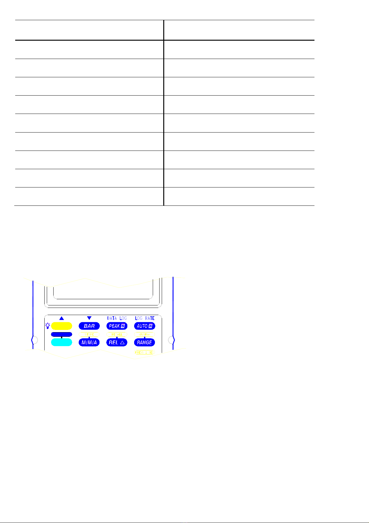
4.8 Range
* It switches meter auto ranging or manual ranging and range change in
manual range mode.
* Pressing this key for 2 sec turns manual ranging to auto ranging mode.
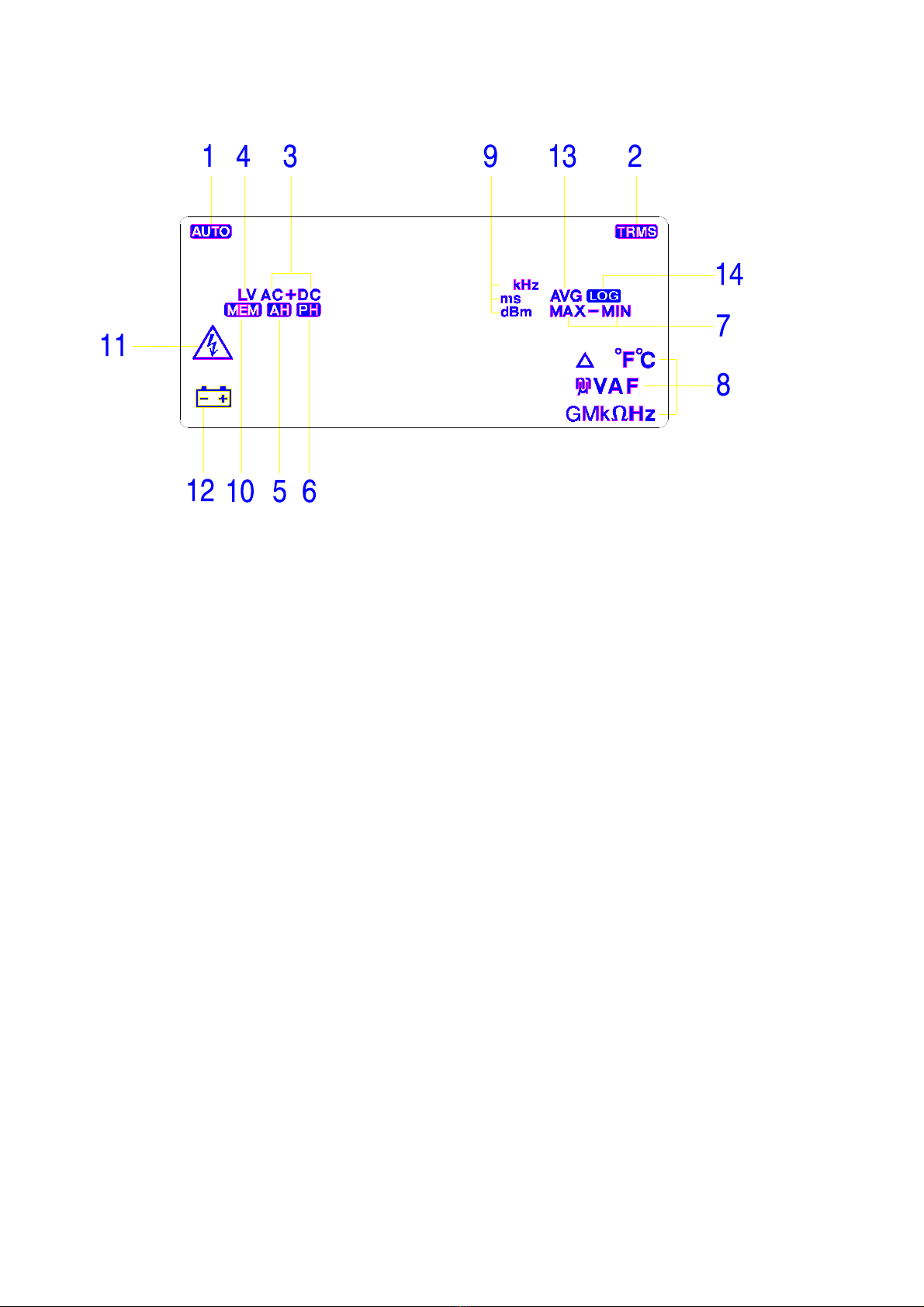
4.9 dB/dBm
* Pressing RANGE key for ≧2 sec enables "dB/dBm" function in AC Volt
mode; One press in this mode toggles dB and dBm.
* The reading of dB or dBm appears on sub-display, reference resistance
fordBmis600Ωand reference voltage for dB is 1V.
* Again 2 sec press on this key in this mode escaps.
4.10 STORE
*PressingM/M/Akeyfor ≧2 sec enables "STORE" function, one press
inthismodestores reading just measured, in memory offering up to 1000
stores.Whenstore is full, Every press beeps twice.
* Again 2 sec press on this key in this mode escaps.
* Power-up with PEAK key pressing to clear stores.
4.11 RECALL
*PressingREL △key for ≧2 enables "RECALL" function.
*Again2secpresson this key in this mode escaps.
* In RECALL mode, use arrow keys (“△” , “ ▽“) marked above yellow
andBARkeystoscrolland veiw up and down the stored readings;
arrow keys perform scroll rate of 10 data/sec when is pressed ≧2
secandhold.
4.12 RED (Data Log)
*Predictions:A.Dataquantities : 40K readings form as sequence
numberon sub-display up to 9999 and each 1/4
scale of bar indicates 10K. (for 109N only)
B.RANGEfunctionisonly enable in just data log mode.
C.Anyposition(measuring function) change escaps out
withoutstoringanydatatomemory.
D. Max. Pause time is 4095 seconds, exceed pause
timestores as 4095 seconds.
E. Max. Pause and Log Rate setting quantities are 3.6K.
F.AutoPower Off function is disabled.

*PressingBLUEkey ≧2 sec turns meter into Data log mode, then
can be chose desired Data log function.
* Again 2 sec press on this key in this mode while not in any
DataLogfunction mode escaps, otherwise, any press on this
key is invalid.
4.12.1 LOG RATE
*SelectableLogRatehas0.5", 1", 10", 30", 60", 120", 180", 240" 300”,
360”, 480” and 600”.
*OnepressonAUTOHkey (LOG RATE) enables this function, the 1st
defaultisonsub-display,use"▼" or "▲" to select Log Rate period for
datalog-in.
*Thedefault(1st)Log Rate is adapted to measuring requirements.
*Againpressthiskeyoncein this mode confirms the Log Rate for log-in
andescaps.
4.12.2 DATA LOG-IN
*PressingonPEAKHkey ≧2 sec enables data log-in function.
* Meter starts storing measured reading referring to log rate selected into
memory.
*Onepressonthiskeyinthismode interrupts data log-in with “PAUS” on
sub-displayforlogratere-setting.
* While data log-in performing, the “—” sub-display is blinking for storing
indication.
* When stores data at 40Kth (6Kth for 107N), data log-in stops, the bar is
full(for109only),sub-display keeps blinking “—” and showing FULL.
4.12.3 DATA LOG-OUT
* One press on PEAK H key (DATA LOG) enables data log-out function
whenisjustindatalog mode, sub-display appears sequence number
ofthislogged-in reading has displayed on main display.
*Thefirstdatadisplayed when just enabled data log-out is the last reading
logged-in.
* In this mode, one press on "▼" or "▲" key sequentely steps up or down
the logged-in data.
*Pressingon"▼" or "▲" key ≧2 sec performs sequentely steps up or
downthelogged-in data with 10 data/sec display rate and stops at the
readingwhen the key is released.
* In this mode, one press M/ M/ A key toggles maximum and minimum
values logged-in, pressing on ≧2 sec escaps.
* In this mode, press RANGE key and then press on "▼" or "▲" key
togglestheturningpointslogged-in with “MAX” or “MIN” symbol depending

onthecomparisonfromcurrent reading and next reading. Press Range
keyagaintoescape.
4.12.4 ▲: Scrolls up data of function selected.
4.12.5 ▼: Scrolls down data of function selected.
4.13 DIGIT
* Pressing on BAR key for ≧2 sec enables “DIGIT” function, again 2 sec
pressing excapes.
* Press under this mode toggles 20000 / 4000 count modes.
* Rotate to power OFF then on to reset to 20000 count mode (default).
* This key is not available on following items.
4.13.1 200MΩand 2GΩranges of Resistances function.
4.13.2 “9” / “” position.
4.13.3 “” position.
4.13.4 “Hz” / “%DF” position.
4.13.5 “°C “ / “°F “ position.
5 OPERATION
5.1 VOLTAGE MEASUREMENTS (AC, DC, AC + DC) (Set to autoranging mode
for unknown voltage measurements).
*Setdial.
* Choose AC, DC or AC + DC

* Connect leads
* TheAC and AC + DC measurements provide a true RMS measurement.
* In AC mode, the frequency of the measured signal ≧20% of full scale is
displayed on sub-display.
5.2 Milli VOLTAGE MEASUREMENTS (AC, DC, AC + DC)
*Setdial.

* Choose AC, DC or AC + DC
*Connect leads
* TheAC and AC + DC measurements provide a true RMS measurement.
* In AC mode, the frequency of the measured signal ≧20% of full scale is
displayed on sub-display.

5.3 OHM AND LOW VOLTAGE OHM MEASUREMENTS
*Setdial.
* Choose Ωor LV Ω
*Connect leads
* #CAUTION : Remove all power from the circuit before connecting the test
leads.
* LV setting reduces the maximum test voltage level to about 0.5V to avoid turning
on semiconductor devices.
* Remove individual components from circuitry for best results.

5.4 DIODE TEST
* Set dial.
* Choose diode test.
*Connect leads
Forward bias
Good = 0.4 to
0.9V
Bad = o or = >
2.0V
Reverse bias
Good = OL
Bad=
<2.0V

#CAUTION : Remove all power from the circuit before connecting the test leads.
* Remove individual components from circuitry for best results.
5.5 CONTINUITY CHECK
*Setdial.
* Choose diode test.
*Connect leads

#CAUTION : Remove all power from the circuit before connecting the test
leads.
* The beeper sounds if the resistance of the circuit is less than 50Ω.
5.6 CURRENT MEASUREMENTS (AC, DC, AC +DC)
*Setdial.

* Choose AC, DC or AC + DC
* Connect leads
* #CAUTION : Limit large current measurements ( 10 to 20A) to 30 seconds
andallowtwominutes of cooling between measurements.
* Do not connect to circuits with > 600V.
* TheAC and AC + DC measurements provide true RMS.
* In AC mode, the frequency of the measured signal ≧20% of full scale is
displayed simultaneously.

5.7 CAPACITANCE MEASUREMENTS
* Set dial.
* Connect leads, zero stray capacitance for low capacitance measurements.
* #CAUTION : Remove all power from the circuit and discharge Capacitor to be
measuredbefore connecting the test leads.
* Remove individual components from circuit for best results.
5.8 FREQUENCY AND DUTY FACTOR MEASUREMENTS
*Setdial.
* Choose period or duty factor on sub-display.
Table of contents