3B SCIENTIFIC Escola 100 User manual

3B SCIENTIFIC®PHYSICS
1
Analogue Multimeter Escola 100 1013527
Instruction sheet
12/15 SD/JS
1 Display with mirror scale
2 Slotted screw for zero calibration
3 Calibration trimmer for setting centre zero point
4 Rotary switch to select the measurement range
5 Four-way switch
6 Voltage measurement socket
7 Current measurement socket for up to 3 A and for
continuity tests
8 Current measurement socket for up to 10 A
9 Safety ground socket
1. Description
The ESCOLA 100 is an electronic meter with a
mirrored dial for measurements of current and
voltage involving analogue techniques for use in
training, education and work placements.
The meter can handle measurements of current
and voltage values up to 10 A or 600 V and also
allows the zero point to be set up in the centre of
the scale for measurement of DC quantities and
for continuity tests featuring an acoustic signal.
AC quantities with frequencies of up to 40 kHz can
be measured. All the possible measuring ranges
can be selected by means of a single rotary
switch.
The device is protected by a fuse and authorised
for measurements on wiring installations in (CAT
III), e.g. in distribution boxes/consumer units. The
current measuring ranges are resistant to long-
term overloading up to 10 A. Generous protection
of all the current ranges by means of semiconduc-
tor circuit breakers prevents the fuse blowing un-
intentionally in many cases.
Switching between measuring ranges does not
break any circuits connected to the equipment.
This means it is possible to carry out measure-
ments on voltage converters, for example, without
causing induction surges. Resistance R, conduct-
ance G,impedance Zand admittance Ycan easily
be determined as quotients of current and voltage
measurements thanks to the non-interrupting
switch capability without the need to change the
wiring.

2
2. Safety instructions
The analogue multimeter conforms to safety regu-
lations for electrical measurement, control and la-
boratory equipment, as specified in DIN EN 61010-
1, protection class 2 and to measuring category
CAT III for up to 600 V. The nominal voltage be-
tween the phase conductors and the neutral for
voltage and current measurements (in circuits di-
rectly connected to mains electricity) must not ex-
ceed 600 V in order to conform to CAT III.
The meter is intended for measurements within its
measuring ranges and in a measuring environ-
ment as described in detail in the course of this
manual. Safe operation of the multimeter is gua-
ranteed if it is solely used as specified. Safety can-
not be guaranteed, however, if the multimeter is
used incorrectly or handled without due care and
attention.In orderto avoid serious injury due to cur-
rent or voltage shocks, the following safety instruc-
tions are to be observed at all times.
The multimeter may only be used by persons who
are able to recognise the risks of contact and take
due precautions to avoid them. Voltages in excess
of 33 V AC (RMS) or 70 V DC are to be regarded
as actively dangerous if the current, charge or en-
ergy stored should exceed certain values (see
DIN EN 61010-1).
Carefully read the instruction manual before
using the multimeter and obey the instruc-
tions therein.
The multimeter may only be used in a dry,
dust-free environment with no risk of explo-
sions occurring.
The assumption needs to be made that unfore-
seen voltages may be present in the vincinity of
objects being measured (e.g. faulty equipment).
Before using the multimeter, check the hou-
sing and measuring leads for damage and if
there should be any malfunctions or visible
damage, the multimeter is not to be used. Pay
specific attention to the insulation for the mea-
suring sockets.
The multimeter may not be used to make
measurement on circuits which exhibit corona
discharge (high voltage).
Particular care is to be taken when making
measurements on high-frequency circuits
where dangerous voltages may arise due to
superimposition of components.
The authorised measuring range is not to be
exceeded. If measurements are made when
the magnitude of the variable is unknown, al-
ways select a large measuring range before
shifting down to lower ones.
Make very sure that the voltage value be-
tween the measured contact and earth or be-
tween the ground socket and the measure-
ment socket does not exceed 600 V.
Before using the analogue multimeter to
check that a voltage source is not exhibiting
any actual voltage, check that the meter is
working properly by selecting the battery test
function.
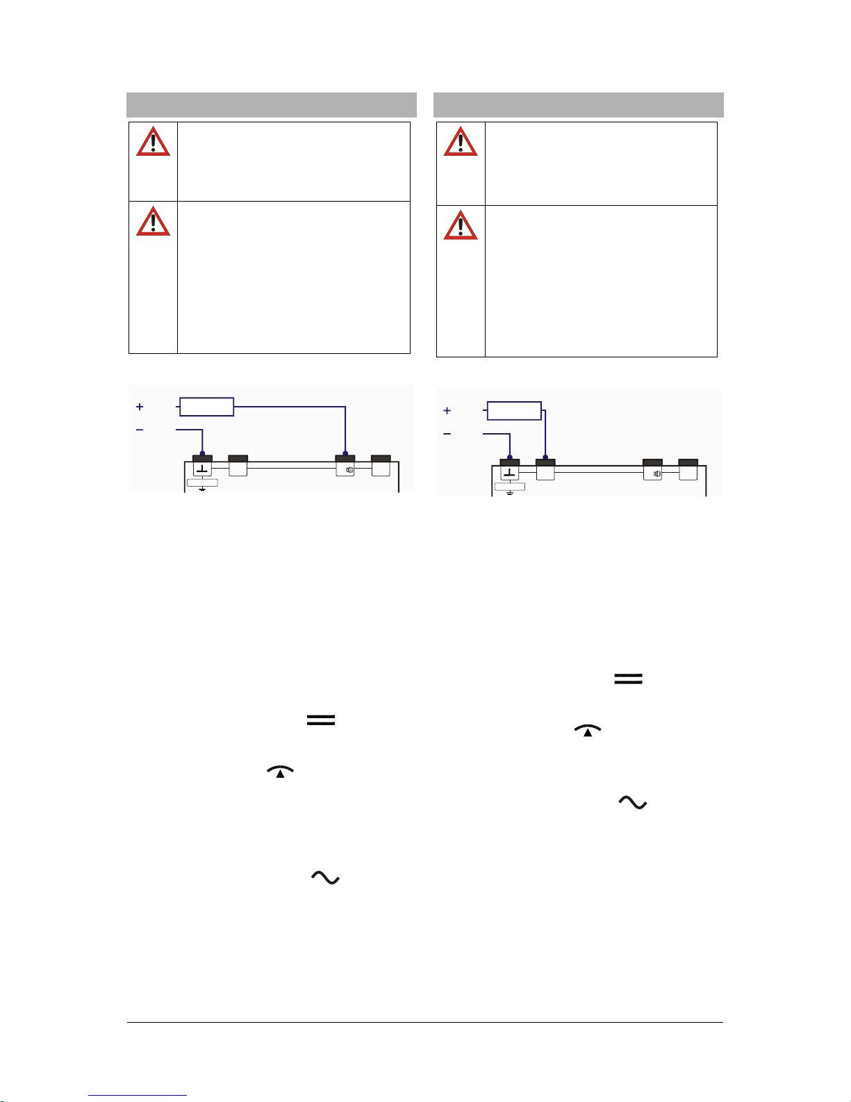
When measuring current, make sure the elec-
tricity is turned off before the analogue multi-
meter is connected into the circuit.
When making measurements, always con-
nect the ground lead first. Disconnect the sig-
nal measurement lead before unplugging the
ground.
Turn off the multimeter before opening the
casing, disconnect the power to the circuit and
the measuring leads from the multimeter.
If measurements are made where there are
any risks of coming into contact with electric-
ity, a second person is to be informed.
When the multimeter is used by teenagers,
trainees etc., a suitable person should super-
vise to ensure the equipment is used safely.
If measurements are to be made where volt-
ages exceed 33 V AC (RMS) or 70 V DC, be
especially careful and only use safety experi-
ment leads.
Measuring categories according to DIN EN
61010-1.
CAT I or unstipulated: Approved for measure-
ments in circuits which are not directly connected
to the low voltage mains grid (e.g. batteries).
CAT II: Approved for measurements in circuits
which are directly connected, by a mains lead and
plug for instance, to the low voltage mains grid
(e.g. household or office appliance and lab
equipment).
CAT III: Approved for measurements in circuits
which are part of a building’s wiring installation
(e.g. stationary consumers, distribution terminals,
appliances connected directly to the distribution
box).
CAT IV: Approved for measurements in circuits
which are directly connected to the source of the
low voltage mains (e.g. electricity meters, main
service feed, primary excess voltage protection).

3
3. Technical data
Display:
Scales: 0 … 10, linear
0 … 3, linear
Scale length: 80 mm
Pointer deflection: 0…90°
Electrical
zero-point offset: in all DC ranges
Measurements:
Voltage ranges: 0.1/ 0.3/ 1/ 3/ 10/ 30/
100/ 300/ 600 V AC/DC
Current ranges: 0.1/ 0.3/ 1/ 3/ 10/ 30/
100/ 300 mA AC/DC
1/ 3/ 10 A AC/DC
Input resistance: 1 MΩ AC/DC
Voltage drop when
measuring current: 100 mV approx. AC/DC
Reference conditions:
Ambient temperature: 23 °C
Operating alignment: Vertical/horizontal
Signal form: Sine (1% max. discrep-
ancy)
Peak factor:
2
Frequency range: 40 Hz … 50 Hz… 5 kHz
Accuracy (at reference conditions):
DC quantities: Class 2
DC with
zero-point offset: Class 5
AC quantities: Class 3
Extended frequency range (class 10):
0,3 –600 V: 40 Hz … 50 Hz … 40 kHz
3 –3000 mA: 40 Hz … 50 Hz … 40 kHz
10 A: 40 Hz … 50 Hz … 40 kHz
Resistance, conductance, impedance, admit-
tance
These quantities can be determined by forming
various quotients involving “simultaneous meas-
urements” of current and voltage.
R= U/ I: below 1 mΩ … above 10 MΩ
S= I/ U: below 1 µS … above 30 S
Z= U/ I: below 1 mΩ … above 10 MΩ,
40 Hz … 40 kHz
Y= I/ U: below 1 µS … above 30 S,
40 Hz … 40 kHz
Overload protection:
Voltage ranges: 600 V long-term in all
voltage ranges
Current ranges: 10 A of long-term load-
ing in 3-A and 10-A
ranges
Electrical safety:
Safety specifications: EN 61010-1
Measuring category: CAT III: 600 V
Contamination level: 2
Protection type: IP20
Connectors: 4-mm safety sockets
Protection:
Fuses: 2x FF 10 A/600 V
(10 x 38 mm)
Breaking capacity: at least 10 kA
3B order number: 5008564
Power supply:
Battery: 1x 1.5 V, AA IEC LR6
Automatic cut-off after: 45 min ± 10 min
Electromagnetic compatibility:
Interference emission: EN 55011:2009
Interference resistance: EN 61326-1:2013
Operating conditions:
Ambient temperature: 5 °C ... 23 °C … 40°C
Storage temperature: -20 … 70°C
Relative humidity: <85% with no condensa-
tion
General data:
Shock test: max. 147 m/s²
Dimensions: 100x150x50 mm3 ap-
prox.
Weight: 300 g approx.

4
4. Symbol legend
Hazard, read instruction sheet
Moving coil galvanometer
Apparatus with electronic amplifier
DC quantities accuracy class 2
AC quantities accuracy class 3
Use in vertical position
Use in horizontal position
Dial position when turned off
Dial position for battery test when bat-
tery charge is satisfactory
Ground symbol
CAT III
Measuring category III
Earth symbol
Meter on for measurements with centre
zero point
Meter on for DC measurements
Meter on for AC measurements
Meter switched off
Battery test
Continuity test
EU conformitymark
Electrical safety assured by double in-
sulation
Do not dispose in normal domestic
waste
For use indoors only
5. Initial calibration
Set up the ESCOLA 100 meter either horizon-
tally or vertically.
Do not connect measuring leads to begin with.
Set the four-way switch to or .
The needle will point to the zero point of the dial.
If it does not, the amount of charge of the battery
should be checked.
6. Operation
6.1 To switch on:
Set the four-way switch to ,
or .
6.2 Checking battery charge:
Set the four-way switch to
Disconnect all measuring leads.
Set the rotary switch to .
If the battery is sufficiently charged, the needle will
point to the following range indication, . If
this is not the case, the battery will need to be re-
placed immediately.
6.3 Zero point calibration:
Set up the analogue multimeter either hori-
zontally or vertically.
Set the four-way switch to .
Turn the rotary switch to 600 V.
Connect the common/ground socket and the
voltage measurement socket together by
means of a short connecting lead.
Turn the zero-point trimmer screw to adjust
the zero point as needed.
6.4 Zero point calibration for centre zero
point:
For measurements of DC current and voltage, the
zero point of the scale can be moved to the centre
of the dial.
Disconnect all measuring leads.
Set the four-way switch to and turn the
rotary switch to a DC current or voltage range,
Use the zero-point trimmer to line up the nee-
dle precisely in the centre of the dial.
6.5 To switch off:
Set the four-way switch to .
When the meter is turned off, the needle points to
.
6.6 If a measurement is interrupted by battery
cut-out:
After 45 minutes of use, the multimeter is auto-
matically shut off and the needle will then point to
.
To switch back on:
Set the four-way switch of the analogue multi-
meter to off and then use it to turn the meter
back on.

5
7. Current measurements up to 3 A
The ESCOLA 100 may NOT be used
to measure circuits connected directly
to low-voltage mains sources. See
page 2 of “Measurement categories”
as specified in DIN EN 61010-1.
The nominal voltage of the current
source may not exceed 600 V.
The multimeter is to be connected
in series with the load on the side
where the voltage with respect to
ground is lowest!
Turn off the circuit before the Es-
cola 100 meter is connected into
it.
If measurements are made when the magni-
tude of the variable is unknown, always select
a large measuring range before shifting down
to lower ones.
Connect the terminal at the lower potential to
the common/ground socket.
Connect the common/ground lead first and
only then the signal lead.
7.1 DC currents up to 3 A:
Set the four-way switch to .
Alternatively, if measurements areto be made
with the zero point in the centre, then set the
four-way switch to .
Select the required current measuring range
to a range measured in mA or A.
7.2 AC currents up to 3 A:
Set the four-way switch to .
Select the required current measuring range
to a range measured in mA or A.
8. Current measurements up to 10 A
The ESCOLA 100 may NOT be used
to measure circuits connected directly
to low-voltage mains sources. See
page 2 of “Measurement categories”
as specified in DIN EN 61010-1.
The nominal voltage of the current
source may not exceed 600 V.
The multimeter is to be connected
in series with the load on the side
where the voltage with respect to
ground is lowest!
Turn off the circuit before the Es-
cola 100 meter is connected into
it.
Set up a measuring range of 10 A.
Connect the terminal at the lower potential to
the common/ground socket.
Connect the common/ground lead first and
only then the signal lead.
8.1 DC currents up to 10 A:
Set the four-way switch to .
Alternatively, if measurements areto be made
with the zero point in the centre, then set the
four-way switch to .
8.2 AC currents up to 10 A:
Set the four-way switch to .
~
~
10A VA,
CAT III 600V
~
~
10A VA,
CAT III 600V

6
9. Voltage measurements
The ESCOLA 100 may NOT be used
to measure directly at low-voltage
mains sources. See page 2 of “Meas-
urement categories” as specified in
DIN EN 61010-1.
The nominal voltage of the voltage
source may not exceed 600 V.
If measurements are made when the magni-
tude of the variable is unknown, always select
a large measuring range before shifting down
to lower ones.
Connect the common/ground lead first and
only then the signal lead.
For measurements of voltage up to 100 mV,
set the rotary switch to the range 0.1
mA/100 mV.
9.1 DC voltages up to 600 V:
Set the four-way switch to .
Alternatively, if measurements areto be made
with the zero point in the centre, then set the
four-way switch to .
Select the required measuring range to a
range measured in V.
9.2 AC voltages up to 600 V:
Set the four-way switch to .
Select the required measuring range to a
range measured in V.
10. Continuity testing
Connect up the component to be tested.
Set the four-way switch to and turn the
rotary switch to . If there is continuity of cur-
rent (R< 1 kΩ), an audible signal will sound.
11. Measuring current and voltage together
The ESCOLA 100 may NOT be used
to measure circuits connected directly
to low-voltage mains sources. See
page 2 of “Measurement categories”
as specified in DIN EN 61010-1.
The nominal voltage of the current
source may not exceed 600 V.
The multimeter is to be connected
in series with the load on the side
where the voltage with respect to
ground is lowest!
Turn off the circuit before the Es-
cola 100 meter is connected into
it.
11.1 DC voltages and currents:
Set the four-way switch to .
Use the rotary switch to set the desired volt-
age measuring range and read off the meas-
urement.
Set a suitable current measuring range and
read off the measurement.
11.2 AC voltages and currents:
Set the four-way switch to .
Use the rotary switch to set the desired volt-
age measuring range and read off the meas-
urement.
Set a suitable current measuring range and
read off the measurement.
~
~
10A VA,
CAT III 600V
10A VA,
CAT III 600V
~
~
10A VA,
CAT III 600V

3B Scientific GmbH ▪ Rudorffweg 8 ▪ 21031 Hamburg ▪ Germany ▪ www.3bscientific.com
Subject to technical amendments
© Copyright 2015 3B Scientific GmbH
12. Battery and fuses
The battery and the two fuses are located under-
neath the back cover of the meter.
One fuse each is provided for the 3 A and 10 A
sockets:
FF10 A/600 V, breaking capacity: at least 10 kA
(3B order number: 5008564)
The polarity is indicated by plus and minus signs
inside the fuse holder compartment. A mechanical
system ensures the battery makes no contact if it
is inserted the wrong way round.
12.1 Battery testing:
Check the amount of charge left in
the battery from time to time.
Flat or leaking batteries should be
removed from the meter.
If the Escola 100 goes unused for a
long period:
Remove the Escola 100’s battery
before reusing.
12.2 Changing the battery:
Before opening the casing:
Turn off the Escola 100.
Disconnect all measuring leads.
Unscrew the back of the casing.
Replace flat batteries with 1.5-V alkaline bat-
teries of size AA IEC LR6.
Place the negative pole of the battery on the
spring.
Close the casing again.
12.3 Changing fuses:
Before opening the casing:
Turn off the Escola 100.
Disconnect all measuring leads.
Unscrew the back of the casing.
Check the fuses.
Blown fuses should be replaced with ones of
the same rating.
Close the casing again.
13. Cleaning
For cleaning, use a soft cloth, slightly mois-te-
ned with alcohol, or a brush.
Electrostatic charging of the display window can
affect the measurements under certain circum-
stances:
To remove such charge, use a soft cloth
slightly soaked in alcohol or a paint brush.
Dirt or moisture in the measurement sockets can
affect readings.
Shake out any dirt that may be in the meas-
urement sockets.
Soak a new swab with isopropyl alcohol and
work around the inside of each measurement
socket.
14. Disposal
The packaging should be disposed of at local
recycling points.
Should you need to dis-
pose of the equipment it-
self, never throw it away in
normal domestic waste. If
being used in private
households it can be dis-
posed of at the local public
waste disposal authority.
Comply with the applicable regulations for the
disposal of electrical equipment.
Do not dispose of the batteries in the regular
household garbage. Follow the applicable le-
gal regulations (UK: Waste Batteries and Ac-
cumulators Regulations, EU: 2006/66/EC).

This manual suits for next models
1
Other 3B SCIENTIFIC Multimeter manuals