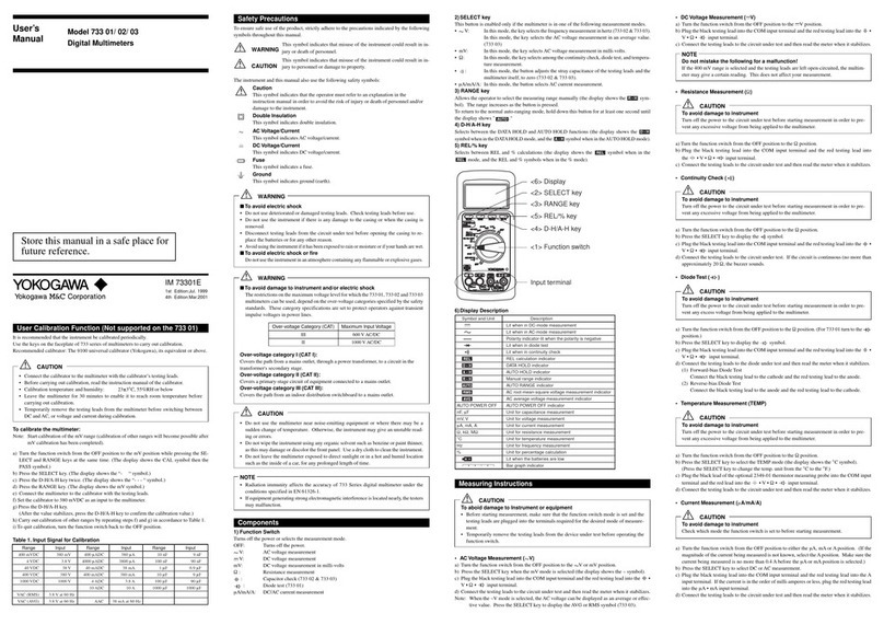
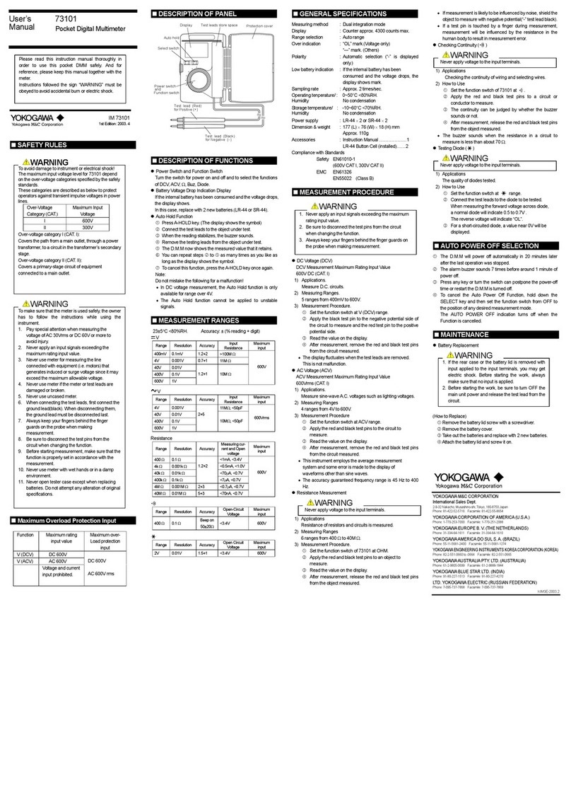
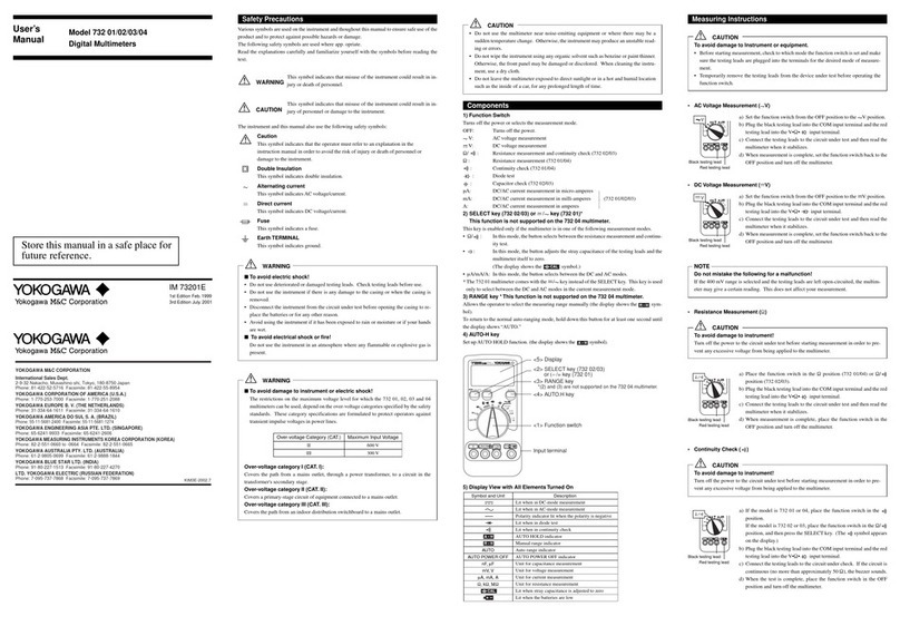
YOKOGAWA TY520 User manual

IM TY530
1st Edition
Nov. 2008(KYOU)
Japanese/
English
この取扱説明書は,いつでも使用できるよう
大切に保管してください。
Store this manual in a safe place for future reference.
TY520, TY530
Digital Multimeter
ディジタルマルチメータ
User's
Manual
保証書付

37
Thank you for purchasing our Model TY520, TY530 Digital Multimeter.
This user’s manual describes the specifications and handling precaution for this Digital
Multimeter.
Before using this Digital Multimeter, thoroughly read this manual to get a clear understanding
on proper use.
Always observe the following instructions.
Failure to do so may result in electric shock or other dangers that may lead to serious injury or
the loss of life.
Yokogawa is in no way liable for any damage resulting from the user’s mishandling of the
product.
For safe use of this product, the following safety symbols are used on the product:
nAbout This Manual
• Everyefforthasbeenmadetoensureaccuracyinthepreparationofthismanual.
However, should any errors or omissions come to the attention of the user, please contact
Yokogawa.
• Thecontentsofthismanualaresubjecttochangewithoutpriornoticebecauseof
improvement in performance or function.
• Allrightsreserved.Nopartofthismanualmaybereproducedinanyfromwithout
Yokogawa's written permission.

38
Regarding Safe Use of This Product
For safe use of this product, the following safety symbols are used on the product and manual:
WARNING
This indicates that the operator must refer to an explanation in the
instruction manual in order to avoid the risk of serious injury or the loss
of life.
CAUTION
This indicates that the operator must refer to an explanation in the
instruction manual in order to avoid the risk of injury or damage to the
product.
Note This indicates information that is essential for handling the instrument
or should be noted in order to familiarize yourself with the instrument’s
operating procedures and/or functions.
Danger! Handle with Care
This symbol indicates that the operator must refer to an explanation in the
instruction manual in order to avoid risk of injury or death of personnel
or damage to the instrument.
Double Insulation
This symbol indicates double insulation or reinforced insulation.
Direct Current
This symbol indicates DC voltage/current.
Alternating Current
This symbol indicates AC voltage/current.
DC/AC
This symbol indicates AC and DC.
Fuse
This symbol indicates a fuse.
Ground
This symbol indicates ground (earth).

39
WARNING
nAlways observe the following instructions. Failure to do so may result in
electrical shock or other dangers that may lead to serious injury or the loss of
life.
Testing leads
• UsetheprobessuppliedbyYokogawawiththisinstrument.
• Donotusetestingleadsthathavedeterioratedoraredefective.
Check testing leads continuity.
• Disconnecttestingleadsfromthecircuitundertestbeforeopeningthecasingtoreplacethe
batteries or for any other reason.
• Disconnect testing leads from the circuit under test before attaching/detaching the testing
leads to/from the instrument.
• Disconnecttestingleadsfromtheinstrumentbeforeopeningthecasingtoreplacethe
batteries or for any other reason.
• Acapisprovidedonthetipofatestinglead.
Useatestingleadwiththecaponforsafety(safetystandards:EN61010-031).
Casing
• Donotusetheinstrumentifthereisanydamagetothecasingorwhenthecasingis
removed.
Fuses
• Usefusesofthespeciedratingwhenthefuseisreplaced.
Operating Environment
• Do not operate the instrument in an atmosphere where any ammable or explosive gas is
present.
• Avoid using the instrument if it hasbeen exposed to rain or moistureor if your hands are
wet.
Disassembly
• Noperson,exceptpersonnelfromYokogawa,isauthorizedtodisassemblethisinstrument.

40
Contents
1. Overview........................................................................................................... 41
2. Measurement Category ..................................................................................... 42
3. Specications .................................................................................................... 43
3.1 GeneralSpecications ............................................................................ 43
3.2 Accuracy ................................................................................................. 45
4. Operation .......................................................................................................... 48
4.1 PrecautionsBeforeMeasurement ........................................................... 48
4.2 Components ............................................................................................ 49
4.3 Measuring Instructions............................................................................ 53
4.3.1 ACVoltageMeasurement ................................................................ 53
4.3.2 DCVoltageMeasurement ................................................................ 53
4.3.3 MeasurementswithSENSOR.......................................................... 54
4.3.4 ResistanceMeasurement.................................................................. 54
4.3.5 Continuity Check ............................................................................. 55
4.3.6 Diode Test ........................................................................................ 55
4.3.7 Temperature Measurement............................................................... 56
4.3.8 Current Measurement ...................................................................... 57
4.3.9 Capacitor Measurement ................................................................... 57
4.3.10 Frequency Measurement ................................................................. 58
4.3.11
FunctiontochangeRMSdetectionto/fromMEANdetection
mode (TY530 only)...............................................................................58
4.3.12Functiontoturnthelteron/off...................................................... 59
4.3.13AUTOHOLDFunction................................................................... 60
4.3.14Relativeandpercentagecalculation................................................ 60
4.3.15 MIN/MAX/AVGFunction(TY530 only)....................................... 61
4.4 Memory Function (TY530 only) ............................................................ 62
4.5 AUTOPOWEROFFFunction............................................................... 64
4.6 Set-upFunction....................................................................................... 65
4.7 AdditionalfunctionssimplysetwhenPOWERON............................... 68
4.8 LCDCheck ............................................................................................. 68
5. UserCalibrationFunction................................................................................. 69
6. BatteryandFuseReplacement ......................................................................... 71
6.1 BatteryReplacement............................................................................... 71
6.2 FuseReplacement ................................................................................... 72
7. Calibration and Maintenance ............................................................................ 73
8 DisposingtheProduct....................................................................................... 73
41
1. Overview
lDisplay
4-digit (LCD)
Maximum Reading: 6000
Bar graph indicator
lSupports a variety of measurement function
Measurement function
DC Voltage, AC Voltage, DC Current, AC Current, Resistance, Frequency, Temperature,
Capacitor, Continuity Check, Diode Test
Other functions
DataHold(D•H),AutoHold(A•H),RangeHold(R•H),
Maximum value* (MAX), Minimum value* (MIN), Average value* (AVG),
Zero Adjustment (Capacitor, Resistance), Relative values, Save to Memory*,
LCD backlight.
*: For model TY530 only
lSwitching detection modes
Effective value (root mean square value) detection (RMS) and mean value detection (MEAN)
can be switched during AC voltage measurement (TY530 only).
l Low-passlter
Thelow-passltercanbeswitchedon/offduringACvoltageorACcurrentmeasurement.
lCommunication: optional communication package is required (TY530 only).
• Measurement data can be transferred to a PC using an optional USB communication
package.
The data can be read by certain applications to make trend graphs or can be converted
intoExcelles.
• ThedatacanalsobeoutputfromanoptionalprinterviaanoptionalRS232cable.
lSafety design
Complied standards: CE standards
Usesacurrent-inputterminalshutterforpreventingwronginput.
Useshigh-performanceUL-standardfuses.

42
2. Measurement Category
WARNING
nMeasurement Category (CAT.)
TherestrictionsonthemaximumvoltagelevelforwhichtheTY520,TY530canbeused,
dependonthemeasurementcategoriesspeciedbythesafetystandards.
Do not apply any input level higher than maximum allowable input.
AC/DC1000V CAT.III
AC/DC600V CAT.IV
Measurement
category Description Remarks
ⅠCAT. I For measurements performed on circuits not
directly connected to MAINS.
ⅡCAT. II For measurements performed on circuits directly
connected to the low voltage installation.
Appliances, portable
equipment, ect.
ⅢCAT.III For measurements performed in the building
installation.
Distribution board,
circuit breaker, ect.
ⅣCAT. ⅣFor measurements performed all the source of the
low-voltage installation.
Overhead wire,
cable systems, ect.
Internal Wiring
Outlet
Entrance
Cable
Fixed Equipment,
etc.
Distribution
Board
CAT. II
Equipment
CAT. I
CAT.IV
CAT. III
Note
RadiationimmunityaffectstheaccuracyoftheTY520,TY530undertheconditions
speciedinEN61326-1.
Useofthisinstrumentislimitedtodomestic,commercial,andlightindustry
applications. If equipment generating strong electromagnetic interference is located
nearly, the instrument may malfunction.

43
3. Specications
3.1 GeneralSpecications
Measurement function:
DC Voltage, AC Voltage, DC Current, AC Current, Resistance,
Frequency, Temperature, Capacitor, Continuity Check, Diode Test
Otherfunctions: Data Hold (D•H), Auto Hold (A•H), Range Hold (R•H), Maximum
value* (MAX), Minimum value* (MIN), Average value* (AVG),
Zero Adjustment (Capacitor, Resistance), Relative values, Save to
Memory*, LCD backlight.
*: For model TY530 only
Measuring method: Σmodulation
Display: 4-digit(LCD)/7-segment
Maximum Reading: 6000
PolarityIndicator:“–”Appearsautomaticallywhenthepolarityis
negative
OverrangeIndicator:“OL”
Low-batteryIndicator:“ ”Appearswhenthebatteriesbecome
low
Measurement cycle: 5 times per second
(except frequency measurement : one time per second, Resistance
measurement(6MΩ/60MΩ):2.5timespersecond,capacitor
measurement(1000μF):max.0.14timepersecond)
Bargraphdisplayapprox25timespersecond(atAC,Ω)
Operating temperature and humidity ranges:
-10to55ºC,80%RHorless(nocondensation)
70%RHorlessat40to55ºC.
Storage temperature and humidity ranges:
-30to70ºC,70%RHorless(nocondensation)
Temperaturecoefcient:
(Accuracyat23±5ºC×0.1)/ºCshouldbeadded.
(Temperatureranges:-10to18ºCand28to55ºC)
Powersupply: AA-size(R6/LR6)1.5Vbatteries:4
Battery life: Approximately 300 hours
(Operating hours of alkaline batteries when in DC voltage-mode.)
Note: The battery life varies depending on the operating conditions.
Insulationresistance:1000VDC,100MΩormore

44
Withstandvoltage: 6.88kVrmsACforveseconds
(across input terminals and casing)
Externaldimensions: Approximately90(W)×192(H)×49(D)mm
Weight: Approximately570g(includingbatteries)
Complied standards: Safety standards
EN61010-1,EN61010-031
CAT.III(Max.inputvoltage:AC/DC1000V)
CAT.IV(Max.inputvoltage:AC/DC600V)
Pollutiondegree2,indooruse,
2000mmax.abovesealevel
EMC standards
EN61326-1ClassB
EN55011ClassBGroup1
Effect of radiation immunity:
Intheradio-frequencyelectromagneticeldof3V/m,accuracyis
withinvetimestheratedaccuracy.
Standard accessories: Batteries : 4
Testingleads:1set(Model98015)
Fuse(included):440mA/1000V(99015),10A/1000V(99016)
User'smanual:1
Blankcover:1
Optionalaccessories:Carryingcase 93029
(for the main unit with testing leads
and communication cable)
Testingleads(1set) 98015
Testingleadswithalligatorclip(1set)
99014
Fuse
440mA/1000V 99015
10A/1000V 99016
Temperatureprobes 90050,90051,90055,90056
Followings are for TY530 only.
CommunicationPackageforDMM
92015(Software,USBadapterand
cable)
PrinterAdapterandCable 97016
Printer 97010
AC adapter (for printer, Europe)
94006
Thermalpaperforprinter(10rolls)
97080

45
3.2 Accuracy
Test conditions:
Temperatureandhumidity:23±5ºCat80%RHorless
Accuracy:±(%ofreading+digits)
Note: Each response time is a value to rated accuracy within selected range.
DC Voltage Measurement V
Range Resolution Accuracy Input Voltage Maximum
Input Resistance
600mV 0.1mV
0.09+2
10MΩ 1000V
DC
1000V
rms AC
6V 0.001V 11MΩ
60V 0.01V
10MΩ600V 0.1V
1000V 1V 0.15+2
NMRR: 60dBormore50/60Hz±0.1%
CMRR: 120dBormore50/60Hz(Rs=1kΩ)
Responsetime:1secmax.
AC Voltage Measurement V
AC Coupling: RMS value detection, sine wave
MEAN value detection and RMS value calibration (TY530 only)
Range
Resolution
Accuracy Input
Impedance
Maximum
Input
Voltage
50/60Hz 40Hzto500Hz 500Hzto1kHz
600mV 0.1mV
0.5+5 1+5 1.5+5
10MΩ,<200pF 1000V
rms AC
1000V
DC
6V 0.001V 11MΩ,<50pF
60V 0.01V
10MΩ,<50pF600V 0.1V
1000V 1V -
Accuracy:At5to100%ofrangeand1000Vrangeis200to1000V.
lessthan1500Vpeak
Fornon-sinusoidalwaveforms,add±(2%+2%ofF.S.),forCrestfactor<3.
CMRR:60dBormoreDCto60Hz(Rs=1kΩ)
4countsorlessiscorrectedto0,Responsetime:2secmax.
DC Current Measurement A
Range Resolution Accuracy Voltage Drop Maximum
Input Current
600μA 0.1μA
0.2+2 <0.12mV/μA 440mAProtectedby
a440mA/1000Vfuse.
6000μA 1μA
60mA 0.01mA <3.3mV/mA
600mA 0.1mA
0.5+56A 0.001A <0.1V/A 10AProtectedby
a10A/1000Vfuse.
10A 0.01A
Maximum measurement current : 440mA at 600mA range
Responsetime:1secmax.

46
AC Current Measurement [RMS] A
RMS value detection, sine wave
Range Resolution Accuracy Voltage
Drop
Maximum
Input Current
50/60Hz 40Hzto1kHz
600μA 0.1μA
0.75+5 1.5+5
<0.12mV/μA 440mAProtectedbya
440mA/1000Vfuse.
6000μA 1μA
60mA 0.01mA <3.3mV/mA
600mA 0.1mA
6A 0.001A <0.1V/A 10AProtectedbya
10A/1000Vfuse.
10A 0.01A
Accuracy:At5to100%ofrangeand10Arangeis2to10A.
Maximum measurement current : 440mA at 600mA range
Fornon-sinusoidalwaveforms,add±(2%+2%ofF.S.),forCrestfactor<3.
4 counts or less is corrected to 0, Response time: 3 sec max.
ResistanceMeasurementΩ
Range Resolution Accuracy
Maximum
Measuring
Current
Open-loop
Voltage
Input
Protective
Voltage
600Ω 0.1Ω
0.4+1
<1.2mA <3.5V
1000Vrms
6kΩ 0.001kΩ <110μA
<1.3V
60kΩ 0.01kΩ <13μA
600kΩ 0.1kΩ <1.3μA
6MΩ 0.001MΩ 0.5+1
<130nA
60MΩ 0.01MΩ 1+2(0~40MΩ)
2+2(40~60MΩ)
Accuracyisspeciedafterzeroadjustmentat600Ωto6kΩ(Resistance)
Responsetime:2secmax.at600Ωto600kΩ,10secmax.at6Mto60MΩ
Continuity Check
Range Resolution Range of Operation Measuring
Current
Open-loop
Voltage
InputProtective
Voltage
600Ω 0.1Ω
Thebuzzerturnson
for resistances lower
than50±30Ω.
Approx.
<1.2mA <3.5V 1000Vrms
Diode Test
Range Resolution Accuracy Measuring Current
(Vf=0.6V)
Open-loop
Voltage
InputProtective
Voltage
2V 0.001V 1+2 Approx. 0.5mA <3.5V 1000Vrms

47
Temperature Measurement TEMP
Range Resolution Accuracy InputProtective
Voltage
-50~600°C 0.1°C 2+2°C 1000Vrms
UseoptionalTemperatureProbe:ThermocoupleTypeK
Capacitor Measurement
Range Resolution Accuracy InputProtective
Voltage
10nF 0.01nF 2+10
1000Vrms
100nF 0.1nF
2+51μF 0.001μF
10μF 0.01μF
100μF 0.1μF 3+5
1000μF 1μF
Accuracyisspeciedafterzeroadjustmentat10nto1μF(Capacitance).
Frequency Measurement Hz
AC Coupling, Maximum Reading 9999
Range Resolution Accuracy Input Voltage
10.00to99.99Hz 0.01Hz
0.02+1
0.2to600Vrms
90.0to999.9Hz 0.1Hz
0.900to9.999kHz 0.001kHz 0.4 to 600Vrms
9.00to99.99kHz 0.01kHz 0.8to100Vrms

48
4. Operation
4.1 Precautions Before Measurement
n
Examining Items Contained in the Package
After opening the package, be sure to examine the product as instructed below before use.
Should the delivered product be the wrong model, lack any item, or show any aw in its
appearance, contact the vendor from which you purchased the product.
n
Precautions of Operation and Storage
CAUTION
• Insertthebatteriesintheinstrumentbyreferringto“6.1BatteryReplacement.”
• ABlankcoverisprovidedontheupperpartofbackcasing.
Don’tremovetheBlankcoverexceptwhentheUSBadapterorPrinteradapteris
connected (TY530 only).
• Donotusetheinstrumentnearnoise-emittingequipmentor
where there may be a sudden change of temperature. Otherwise, the instrument may
give an unstable reading or errors.
Removal of Dirt
Do not wipe the instrument using any solvent (chemicals) such as benzine or paint
thinner, as this may damage or discolor the front panel.
Useadryclothtocleantheinstrument.
Storage Conditions
• Donotleavetheinstrumentexposedtodirectsunlight or in a hot and humid location
such as the inside of a vehicle, for any prolonged length of time.
• Iftheinstrumentwillnotbeusedforaprolongedperiod,removethebatteries.

49
4.2 Components
nPanel Description n
Testing leads
Display (LCD)
Function switch
Input terminal block
SHIFT key
RANGE key
HOLD (SAVE) key
LIGHT (READ) key
RE
SELECT (PRINT) key
L /% key
MIN/MAX(LOG) key
(TY530 only)
MEMORY
k
ey
(TY530 only)
BlackRed
Caps of Testing leads
Actions indicated in parenthesis are available at Memory Function(TY530 only).

50
1) Function switch
Turns off the power or select the measurement mode (function).
OFF Turns off the power ΩResistance measurement
V AC voltage (V) measurement Capacitor measurement
V DC voltage (V) measurement TEMP Temperature measurement
/mV DC/ACvoltage(mV)measurement
(SENSOR mode) μA
mA
A
DC/ACcurrentmeasurement
Continuity Check
Diode Test
2) SELECT key
Pressingthiskeyin eachmeasurementmodes(function)describedaboveselectsother
measurement modes (function).
V Frequency measurement
/ mV AC voltage (mV) measurement
(AC SENSOR measurement in the SENSOR mode)
Diode Test
μA/mA/A AC current measurement
3) RANGE key
Allows the operator to select the measuring range.
Fixedranges :Thedisplayshowsthe“R•H”symbol.
The range increases every time this key is pressed.
AUTOrange :Thedisplayshowsthe“AUTO”symbol.
To return to the auto-ranging mode, hold down RANGE key for
more than one second.
4) HOLD key
SelectsbetweentheDATAHOLDandAUTOHOLDfunctions.
To cancel functions, press this key once again.
DATA HOLD: Holds the display readings.
Thedisplayshowsthe“D•H”symbol.
AUTOHOLD: Holdsthemeasuredvaluewhenthetestingleadsarehandled.
Thedisplayshowsthe“A•H”symbol.

51
5) LIGHT key
PressthiskeyoncetoturnontheLCDbacklightforapproximatelyoneminute.
The LCD backlight is lit for approximately one minute.
(To postpone turned on time, press this key once again.)
To cancel the function, hold down this key for more than one second.
6)REL∆/%key
The instrument can calculate relative values or differences, and percentage values from the
reference measurement values.
1: RelativeCalculation
Thedisplayshowsthe“ ”symbol.
The sub-display shows the reference value.
2: PercentageCalculation
Thedisplayshowsthe“ ”,“%”symbol.
The sub-display shows the reference value.
7) MIN/MAXkey(TY530only)
Displays the minimum value (MIN), maximum value (MAX) and average value (AVG)
during measurement.
PressingthiskeystartsrecordingandatthesametimethedisplayshowsMIN/MAX/AVGto
releaseAUTOPOWEROFF.
8) MEMORYkey(TY530only)
Data can be stored in internal memory using this key.
Usedwhenoutputtingtoprinterwiththeoptionaladapterandcable.
9) SHIFT key
Whilethiskeyispressed,“Shift”appearsonthedisplay.
Then pressing the following keys enables the following settings.
SHIFT+
LIGHT key Set-up function
RANGE key Change to [RMS] mode (TY530 only)
REL key Change to [MEAN] mode (TY530 only)
HOLD key Turnlteron/off
SELECT key Switch to the SENSOR mode at the mV function

52
■Display(LCD)Description
SymbolandUnit Description
Appears when in DC-mode measurement
Appears when in AC-mode measurement
-Appears when the polarity is negative
Appears when in diode test
Appears when in continuity check
⊿Relative calculation indicator
R・H Fixed ranges indicator
AUTO AUTOrangeindicator
DATA HOLD indicator
AUTOHOLDindicator
LitwheninMIN/MAX/AVG-mode(TY530only)
AUTOOFF Auto power off indicator
RMS Appears in RMS mode
Filter Appearswhilelterison
Shift Appears when the SHIFT key is pressed
nF、μF Unitforcapasitancemeasurement
mV, VUnitforvoltagemeasurement
μA, mA, AUnitforcurrentmeasurement
Ω, kΩ, MΩ Unitforresistancemeasurement
℃Unitfortemperaturemeasurement
Hz, kHz Unitforfrequencymeasurement
% Unitforpercentagecalculation
mV (Sub-display) UnitforSENSOR-modemeasurement(Inputvoltage)
s (Sub-display) UnitforrecordingtimewheninMIN/MAX/AVG-mode(TY530only)
Appears in Memory mode (TY530 only)
SENSOR Appears when in SENSOR mode measurement.
lx UnitcanbeselectedattheSENSORmodeonly.
(sub-display)
RecordingtimeindicatorwheninMIN/MAX/AVG-mode.
(TY530 only)
number of saved data indicator. (TY530 only)
Reference value indicator when relative calculation.
Input voltage value indicator from SENSOR in SENSOR-mode
measurement.
(sub-display) Appears when in DC SENSOR mode measurement
(sub-display) Appears when in AC SENSOR mode measurement
OL Overrange indicator
Appears when the batteries become low
6
Bar graph indicator, Range indicator

53
4.3 Measuring Instructions
WARNING
To avoid damage to instrument or equipment
• Before starting measurement, make sure that the position of function switch and the
input terminals for connecting the testing leads are appropriate for the desired mode of
measurement.
• Temporarilyremovethetestingleadsfromthedeviceundertestbeforeoperatingthe
function switch.
• Verify proper operation on a known source before use or taking action as a result of the
indication of the instrument.
4.3.1 AC Voltage Measurement ( V, mV)
1)Turnthefunctionswitchtothe“ V”or“mV”position.
2)PresstheSELECTkeywhenselectingthe"mV".
(“ ”isdisplayed.)
3)Plugthetestingleadsintotheinputterminals.
4) Connect the testing leads to the circuit under test and then read the value
whenitstabilizes.
Testing leads
RedBlack
4.3.2 DC Voltage Measurement ( V, mV)
1)Turnthefunctionswitchtothe“ V”or“mV”position.
2)Plugthetestingleadsintotheinputterminals.
3) Connect the testing leads to the circuit under test and then read the value
whenitstabilizes.
Testing leads
RedBlack
Note
If“mV”rangeisselectedandthetestingleadsareleftopen-circuited,theinstrumentmay
give a certain reading. This dose not affect your measurement.

54
4.3.3 Measurements with SENSOR (SENSOR)
Settingsforunitandconversionshouldbemadeinadvance.Referto<input,displayandunit
settings of SENSOR mode> mentioned at clause 4.6 Setup Function.
1)Turnthefunctionswitchtothe“mV”position.
2)GettheinstrumentintheDCSENSORmodewiththeSHIFT+SELECTkeys.Pressofthe
SELECT key again to use AC SENSOR.
Inputvoltagewillbedisplayedonthesub-display,andvaluesandunitssetaccordingto“input,
displayandunitsettingsofSENSORmode”mentionedatclause4.6willbedisplayedonthe
main display.
DC SENSOR Range AC SENSOR Range
SENSOR
3) Connect the SENSOR to the input terminal.
4)Readthevaluewhenitstabilizes.
PresstheSHIFT+SELECTkeystoreturntonormalmVmeasurement.
<Exampleofmeasurements:Toconnectacurrentclampsensor>
Thesubdisplayshowstheoutputvoltageofthecurrentclampsensor(mV)=inputvoltageof
the instrument (mV).
The main display shows the current values (based on the preset setting of conversion with the
setup function ) detected by the current clamp sensor. The displayed values can be directly read.
4.3.4 ResistanceMeasurement(Ω)
CAUTION
To avoid damage to instrument
Turn off the power to the circuit under test before starting measurement in order to prevent any
excessive voltage from being applied to the instrument.
1)Turnthefunctionswitchtothe“Ω”position.
2)Plugthetestingleadsintotheinputterminals.
3) Connect the testing leads to the circuit under test and then read the value
whenitstabilizes.
Testing leads
RedBlack
Note
Zero adjustment
Zeroadjustmentisrecommendedforcorrectmeasurement.Afterexecuting1),2)above,
shortthetwotestingleads.PresstheRELkeyforadjust.(Thedisplayshowsthe“0.0Ω”
value.)Thevalue(zeroadjustment)storestillturnoff.

55
4.3.5 Continuity Check ( )
CAUTION
To avoid damage to instrument
Turn off the power to the circuit under test before starting measurement in order to prevent any
excessive voltage from being applied to the instrument.
1)Turnthefunctionswitchtothe“ ”position.
2)Plugthetestingleadsintotheinputterminals.
3) Connect the testing leads to the circuit under test. If the circuit is
continuous (no more than approximately 50Ω),thebuzzersounds.
Testing leads
RedBlack
4.3.6 Diode Test ( )
CAUTION
To avoid damage to instrument
Turn off the power to the circuit under test before starting measurement in order to prevent any
excessive voltage from being applied to the instrument.
1)Turnthefunctionswitchtothe“ • ”position.
PresstheSELECTkeytoselectDiodetest.
(The display shows the symbol.)
2)Plugthetestingleadsintotheinputterminals.
3) Connect the testing leads to the diode and then read the value when it
stabilizes.
Testing leads
RedBlack
<Forward-bias Diode Test>
Connect the black testing lead to the cathode and the red testing lead to the anode.
Silicon diodes should give a reading of approximately 0.5V and light-emitting diodes a reading
betweenapproximately1.5Vand2.0V.
This manual suits for next models
1
Table of contents
Other YOKOGAWA Multimeter manuals

YOKOGAWA
YOKOGAWA CA450 User manual

YOKOGAWA
YOKOGAWA DM7560 User manual

YOKOGAWA
YOKOGAWA 734 01 User manual

YOKOGAWA
YOKOGAWA 73201 User manual

YOKOGAWA
YOKOGAWA 733 01 User manual

YOKOGAWA
YOKOGAWA TY710 User manual

YOKOGAWA
YOKOGAWA 7555 User manual

YOKOGAWA
YOKOGAWA 732 01 User manual

YOKOGAWA
YOKOGAWA 73101 User manual

YOKOGAWA
YOKOGAWA CW10 User manual