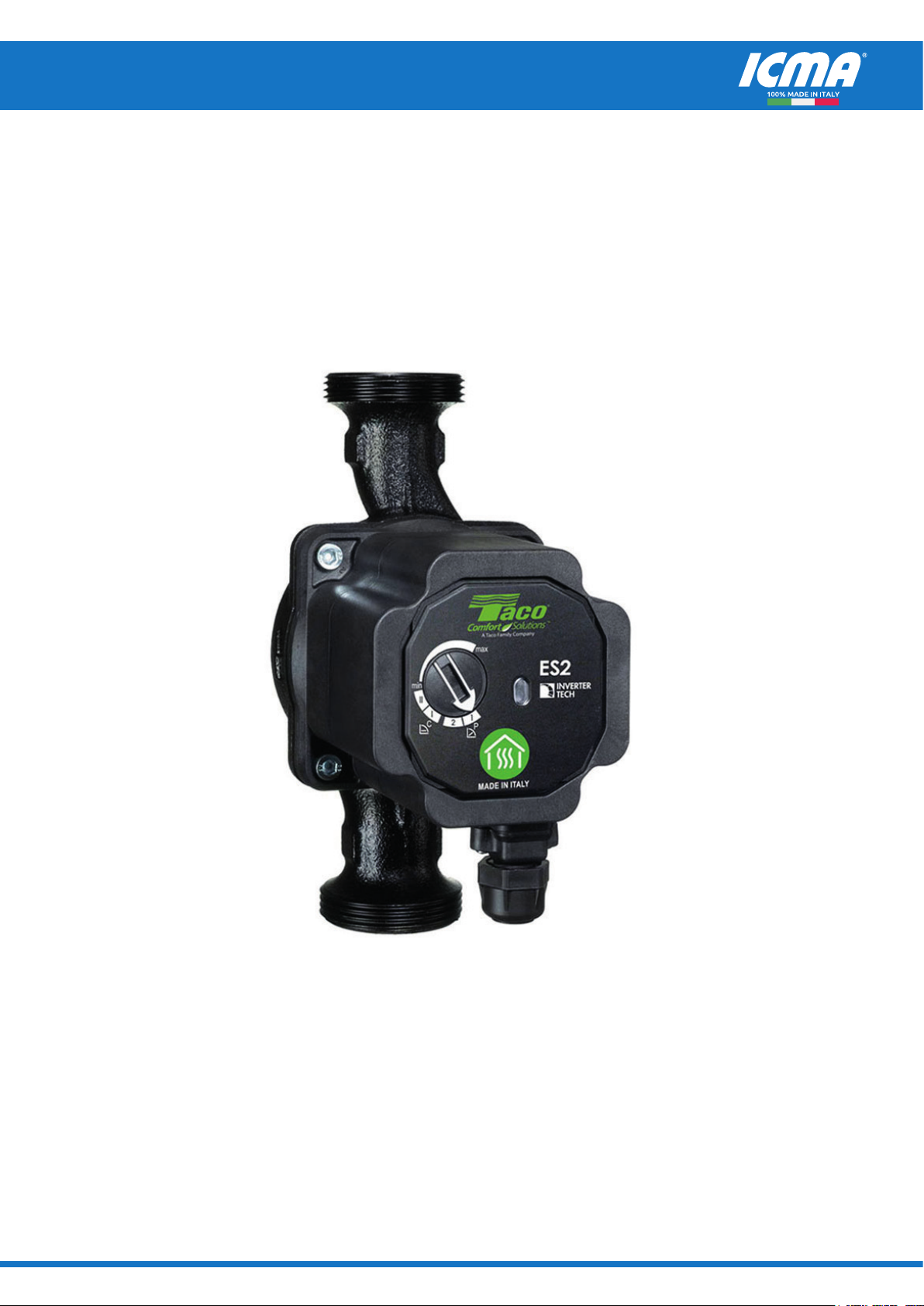
ELECTRONIC CIRCULATOR FOR HEATING SYSTEMS - Art. P329
ICMA S.p.a. - Heating Technologies - www.icmaspa.it FI.P329.EN.C - 1 /2022
Icma
SpA
-
Via
Garavaglia,
4
-
20012
Cuggiono
(MI)
IT
AL
Y
T
el:
+39
02
97249134
-
+39
02
97249135
-
ww
w.icmaspa.it
-
[email protected] Icma
SpA
-
Via
Garavaglia,
4
-
20012
Cuggiono
(MI)
IT
AL
Y
T
el:
+39
02
97249134
-
+39
02
97249135
-
ww
w.icmaspa.it
-
[email protected]4 5
5. Improper use
This is a circulator to be used in heating plants and for the circulation of clean
water without abrasive particles. This is not a submersible pump. Do not use
this circulator:
• With liquids other than water (e.g. ammable liquids, etc.) (EN60335-2-51);
• For handling drinkable water or food related liquids;
• For the circulation of domestic water;
• In locations where special condition prevail, such as the presence of a corrosive
or explosive atmosphere (dust, vapor or gas) (EN60335-2-51);
• For other than intended use.
Never run the circulator dry. The circulator must be always fully lled with
water when operating.
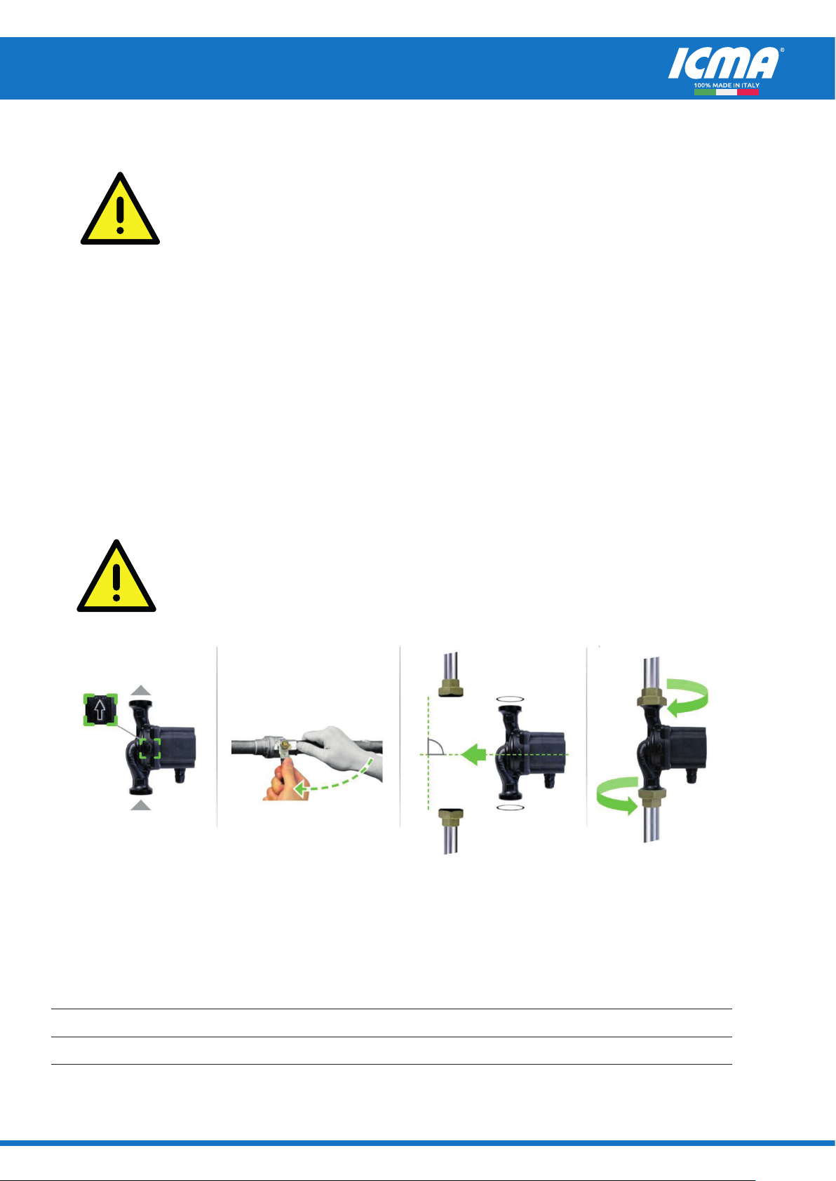
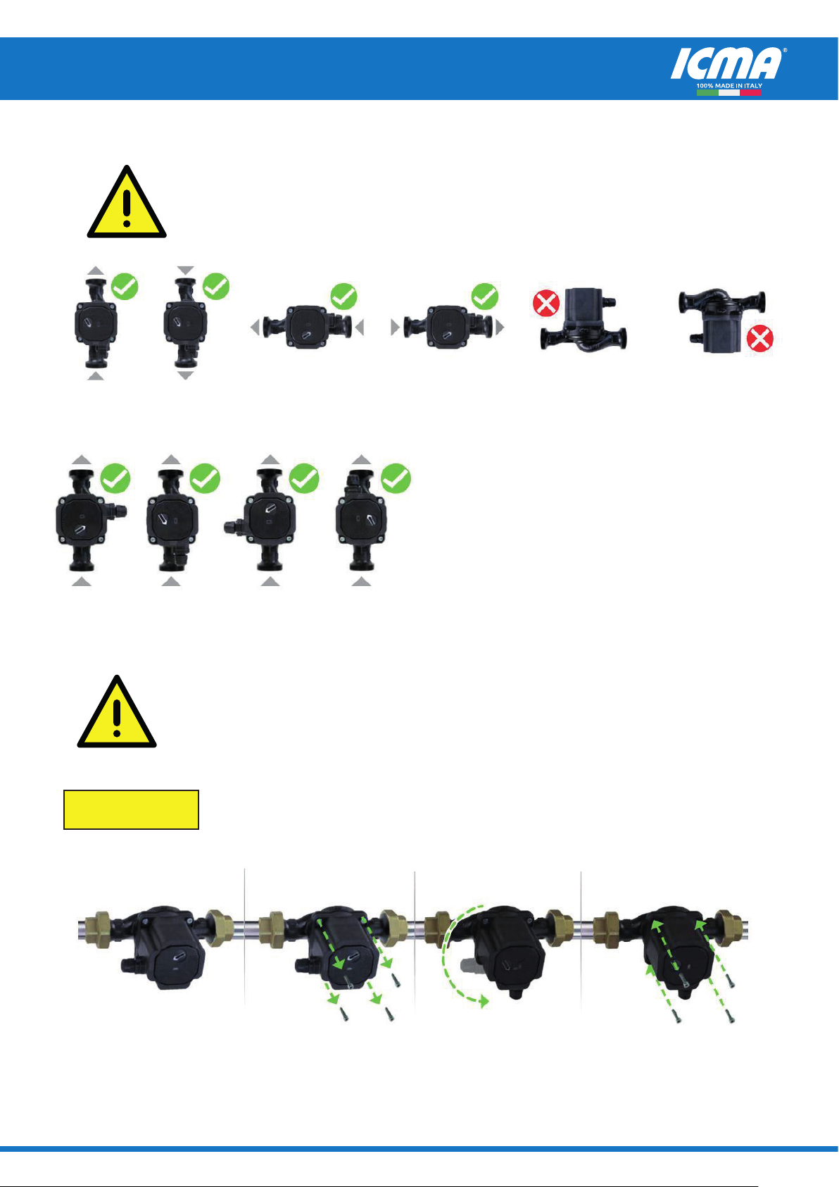
6. Installation
The circulator must be mounted in a stable/xed position in a dry, well
ventilated, frost-free, waterproof and protected place, with sucient ventilation
around it. Assemble the circulator only after having ended all welding and
brazing works on the hosing. Before installing the circulator, make sure that
the internal part of the tubes is clean. Install the circulator in an accessible
place for future checks and disassembly procedures. Foresee enough space
for inspections and disassembling.
To avoid circulator overheating, do not place any object on the circulator itself.
7. Electric connection
IMPORTANT: Connection to the power supply must be eected by means of
a xed power cable which is tted with a plug-type connection or an all-pole
isolating switch with a minimum contact opening of 3 mm.
Electrical connection must be carried out only by a qualied electrician and in
accordance with local regulations and both data on the name-plate and the
appropriate diagram inside the terminal box cover.
Follow all safety standards.
Do not connect to mains supply unless circulator is fully and correctly
assembled.
8. Supply cord must be selected following the requirements of EN60335-2-51
Chapter 25. Supply cord must be protected against any kind of mechanical
damage (cuts, abrasion, etc.). It must not touch the pipe or the pump. (EN
60335-2-51). If the insulation of the Supply cord can come in contact with
parts having a temperature exceeding 70°C the supply cord insulation must
be protected, for example, by insulating sleeving having an appropriate
temperature rating. (EN60335-2-51).
9. Connect circulators only to a mains supply protected by a Residual Current
Device (RCD or Ground-Fault Circuit-Interrupter) with a rated residual operating
current not exceeding 30mA.