Icom IC-7800 User manual

1-12
■Rear panel
qANTENNA CONNECTOR 1 [ANT 1] (p. 2-4)
wANTENNA CONNECTOR 2 [ANT 2] (p. 2-4)
eANTENNA CONNECTOR 3 [ANT 3] (p. 2-4)
rANTENNA CONNECTOR 4 [ANT 4] (p. 2-4)
Accept a 50 Ωantenna with a PL-259 plug connec-
tor.
tGROUND TERMINAL [GND] (p. 2-3)
Connect this terminal to a ground to prevent electri-
cal shocks, TVI, BCI and other problems.
yCIRCUIT BREAKER
Cuts off the AC input when over-current occurs.
uRECEIVE ANTENNA B OUT [RX ANT B– OUT]
iRECEIVE ANTENNA B IN [RX ANT B– IN]
Located between the transmit/receive switching cir-
cuit and receiver’s RF stage in SUB band (MAIN
band during split operation).
Connects an external unit, such as preamplifier or
RF filter, using BNC connectors, if desired.
When no external unit is connected, [RX ANT B–
OUT] and [RX ANT B– IN] must be shorted with the
supplied coaxial cable. (p. 2-2)
oTRANSVERTER CONNECTOR [X-VERTER]
(p. 2-5)
External transverter input/output connector.
Activated by voltage applied to [ACC 2] pin 6, or
when the transverter function is in use. (pgs. 2-10,
4-6)
!0 RECEIVE ANTENNA A OUT [RX ANT A– OUT]
!1 RECEIVE ANTENNA A IN [RX ANT A– IN]
Located between the transmit/receive switching cir-
cuit and receiver’s RF stage in MAIN band (SUB
band during split operation).
Connects an external unit, such as preamplifier or
RF filter, using BNC connectors, if desired.
When no external unit is connected, [RX ANT A–
OUT] and [RX ANT A– IN] must be shorted with the
supplied coaxial cable. (p. 2-2)
!2 MAIN POWER SWITCH [I/O] (p. 3-2)
Turns the internal power supply ON and OFF.
!3 AC POWER SOCKET [AC] (p. 2-4)
Connects the supplied AC power cable to an AC
line-voltage receptacle.
!4
EXTERNAL SPEAKER JACK MAIN [EXT-SP MAIN]
(p. 2-5)
!5 EXTERNAL SPEAKER JACK SUB [EXT-SP SUB]
(p. 2-5)
Connects an external speaker (4–8 Ω), if desired.
Receiver
Transmitter
IN
[RX ANT A/B]
OUT
Transmit/Receive
switching circuit
1PANEL DESCRIPTION
MAINSUB
ACC 1
ACC 2
ACC 1
ACC 2
ALC
ADJ
ALC
RELAY
KEY
EXT
KEYPAD
METER
DC OUT
15V
MAX1A
REF I/O
10MHz
-
10dBm
INOUT
REMOTE
RS
-
232C
KEY BOARD
EXT
-
DISPLAY
A
B
S/P DIF
EXT
-
SP
ANT 1 ANT 2 ANT 3 ANT 4
GND
AC
I
X
-
VERTER
A
IN
RX ANT
B
RX ANT
OUT IN
OUT
q w e r u i o !0 !1
!4!5!7!9 !6!8@0@1@2@3@4@5@6@7@8@9#0#1#2#3 #4
!2
!3
t y

1-13
!6 ACCESSORY SOCKET 1 A [ACC 1–A]
!7 ACCESSORY SOCKET 2 A [ACC 2–A]
!8 ACCESSORY SOCKET 1 B [ACC 1–B]
!9 ACCESSORY SOCKET 2 B [ACC 2–B]
Enable connection of external equipment such as a
linear amplifier, an automatic antenna
selector/tuner, a TNC for data communications, etc.
• See p. 2-10 for socket information.
@0 ALC LEVEL ADJUSTMENT POT [ALC ADJ]
Adjusts the ALC levels.
No adjustment is required when the ALC output
level of the connected non-Icom linear amplifier is
0 to –4 V DC.
@1 ALC INPUT JACK [ALC] (p. 2-7)
Connects to the ALC output jack of a non-Icom lin-
ear amplifier.
@2 T/R CONTROL JACK [RELAY] (p. 2-7)
Goes to ground when transmitting to control an ex-
ternal unit, such as a non-Icom linear amplifier.
@3 STRAIGHT KEY JACK [KEY] (p. 2-4)
Accepts a straight key or external electronic keyer
with 1⁄4inch standard plug.
• [ELEC-KEY] on the front panel can be used for a
straight key or external electronic keyer. Deactivate the
internal electronic keyer in keyer set mode. (p. 4-12)
@4 EXTERNAL KEYPAD JACK [EXT KEYPAD]
(p. 2-6)
Connects an external keypad for direct voice mem-
ory or electronic keyer control.
Transceiver mute control line (both transmit and re-
ceive) is also supported.
@5 METER JACK [METER] (p. 2-6)
Outputs the receiving signal strength level signal,
transmit output power, VSWR, ALC, speech com-
pression, VDor IDlevel for external meter indication.
@6 DC OUTPUT JACK [DC OUT] (p. 2-6)
Outputs a regulated 14 V DC (approx.) for external
equipment. Connected in parallel with 13.8 V out-
puts of [ACC 1] and [ACC 2]. (max. 1 A in total)
@7 REFERENCE SIGNAL INPUT/OUTPUT
TERMINAL [REF I/O]
Inputs/outputs a 10 MHz reference signal.
@8 S/P DIF INPUT TERMINAL [S/P DIF–IN] (p. 2-6)
@9 S/P DIF OUTPUT TERMINAL [S/P DIF–OUT]
(p. 2-6)
Connects external equipment that supports S/P DIF
input/output.
#0 CI-V REMOTE CONTROL JACK [REMOTE]
(p. 2-5)
➥Connects a PC via the optional CT-17 CI-V LEVEL
CONVERTER for external control of the transceiver.
➥Used for transceive operation with another Icom
CI-V transceiver or receiver.
#1 RS-232C TERMINAL [RS-232C] (p. 2-5)
Connects an RS-232C cable, D-sub 9-pin to con-
nect the IC-7800 to a PC.
Can be used for remotely control the IC-7800 with-
out the optional CT-17, or for RTTY/PSK31 de-
coded signal output. The [RS-232C] interface is
wired as a modem (DCE).
#2 KEYBOARD CONNECTOR [KEYBOARD]
(p. 2-6)
Connects a PC keyboard for RTTY and PSK31 op-
erations.
• USB (Universal Serial Bus) keyboard is supported.
#3 EXTERNAL DISPLAY TERMINAL
[EXT-DISPLAY] (p. 2-6)
Connects to an external display monitor.
• At least 800×600 pixel display is necessary.
#4 ETHERNET CONNECTOR (p. 16-6)
Connects to a PC through a LAN (Local Area Net-
work).
+
_
_
(+)
(_)
NOTE: T/R control voltage and current must be
lower than 16 V DC/0.5 A (or 250 V AC,
200 mA with MOS-FET switching).
1
PANEL DESCRIPTION

2-6
DDRear panel—2
MAINSUB
ACC 1
ACC 2
ACC 1
ACC 2
ALC
ADJ
ALC
RELAY
KEY
EXT
KEYPAD
METER
DC OUT
15V
MAX1A
REF I/O
10MHz
-
10dBm
INOUT
REMOTE
RS
-
232C
KEY BOARD
EXT-DISPLAY
A
B
S/ P DID
EXT-SP
ANT 1 ANT 2 ANT 3 ANT 4
GND
AC
I
X-VERTER
A
IN
RX ANT
B
RX ANT
OUT IN
OUT
External Display
Connects a PC-style
monitor display (at least
800×600 resolution).
Video output signal can
be turned ON and OFF
in set mode (p. 12-12)
[DC OUT]
Outputs regulated 14 V
(approx.) DC for external
equipment power supply.
(max. 1 A capacity)
External keypad
Connects an external keypad for direct voice memory
and memory keyer controls.
Keyboard
Connects an USB type
PC keyboard directly for
RTTY/PSK31 operation,
as well as other text edit
operations.
Connects a PC for
audio signal data
input/output.
48 kHz, 16-bit
Stereo output
(L=Main band;
R=Sub band)
[S/P DEAF IN/OUT]
Connects a PC
via a LAN for the
CPU firmware
update.
Ethernet connector (p. 16-6)
1.5 kΩ
±5%
1.5 kΩ
±5%
2.2 kΩ
±5%
4.7 kΩ
±5%
S1
(T1/M1)
S2
(T2/M2)
S3
(T3/M3)
S4
(T4/M4)
EXTERNAL KEYPAD
3.5 (d) mm; 1⁄8≤plug
Mute switch: Mutes both transmission and
reception when switched ON during trans-
ceive operation, etc.
[METER]
Connects an external meter, etc.
3.5 (d) mm; 1⁄8≤plug
MAIN band meter
SUB band meter
2INSTALLATION AND CONNECTIONS

4-9
DDEditing a memory keyer
The contents of the memory keyer memories can be
set using the memory keyer edit menu. The memory
keyer can memorize and re-transmit 4 CW key codes
for often-used CW sentences, contest serial numbers,
etc. Total capacity of the memory keyer is 70 charac-
ters per memory channel.
•Programming contents
qDuring CW mode operation, push [F-3•KEYER] to
select memory keyer screen.
wPush [EXIT•SET] to select memory keyer menu,
then push [F-2•EDIT] to select keyer edit screen.
• Memory keyer contents of Channel 1 (M1) is selected.
ePush [F-7•M1..M4] several times to select the de-
sired memory keyer channel to be edited.
• Push [F5] to manually increment the contest serial num-
ber.
rPush [ABC] or [123] or [Symbol] to select the char-
acter group, then rotate the main dial to select the
character, or push the keypad for number input.
• [Symbol] appears when [123] is pushed when “123”
character group is selected.
• Selectable characters (using the main dial);
NOTE:
“^” is used to transmit a following word with no
space such as AR. Put “^” before a text string
such as ^AR, and the string “AR ” is sent with no
space.
“✱” is used to insert the CW contest serial num-
ber. The serial number automatically increments
by 1. This function is only available for one mem-
ory keyer channel at a time. Memory keyer chan-
nel M2 used “✱” by default.
✔
For your convenience
When a PC keyboard is connected to [KEYBOARD]
connector on the rear panel, the memory keyer con-
tents can also be edited from the keyboard.
tPush [F-1•Ω] or [F-2•≈] to move the cursor back-
wards or forwards, respectively.
• Pushing [F-3•DEL] deletes a character and [F-4•SPACE]
inserts a space.
yRepeat steps rand tto input the desired charac-
ters.
uPush [EXIT/SET] twice to return normal screen.
[F-1•Ω]
[ABC][123]/[Symbol]
[F-7•M1..M4][EXIT/SET][F-2•≈]
[F-3•DEL] [F-4•SPACE]
4
RECEIVE AND TRANSMIT
•Memory keyer edit screen
Key selection Editable characters
A to Z (capital letters)
0 to 9 (numbers)
/ ? ^ . , @ ✱
•Example—entered “QSL TU DE JA3YUA TEST”
into memory keyer channel 3
CH Contents
M1 CQ TEST CQ TEST DE ICOM ICOM TEST
M2 UR 5NN✱BK
M3 CFM TU
M4 QRZ?
•Pre-programmed contents

12-12
12 SET MODE
Selects the pop-up display for the APF filter width
from ON and OFF.
(default: ON)
Turns the pop-up indication capability when the notch
filter width is changed from ON to OFF.
(default: ON)
Select “ON” when the external display is connected.
(default: OFF)
• At least 800×600 pixel resolution is required for the dis-
play.
Selects the suitable pulse level for the connected ex-
ternal display from H and L. (default: H)
Turns the opening message screen indication capa-
bility ON and OFF. (default: ON)
Sets the memory name indication, during memory
mode operation, ON and OFF. (default: ON)
• ON : The programmed memory name is displayed
above the frequency indication.
• OFF : No memory name is displayed even a mem-
ory name is programmed.
■Display set mode (continued)
Turns the screen saver function ON (15, 30 or 60 min-
utes) and OFF. (default: 60 min.)
The screen saver will acts when no operation is per-
formed for the selected time period to protect the LCD
from the “burn-in” effect.
Selects the screen saver type from “Bound,” “Rota-
tion” and “Twist.” (default: Bound)
The screen saver indication can be displayed for your
reference while pushing and holding [F-5•PREVIEW].

12-20
12 SET MODE
■Miscellaneous (Others) set mode (continued)
Transceive operation is possible with the IC-7800
connected to other Icom HF transceivers or receivers.
When “ON” is selected, changing the frequency, op-
erating mode, etc. on the IC-7800 automatically
changes those of connected transceivers (or re-
ceivers) and vice versa.
Select [RS-232C] connector output data format from
CI-V and Decode.
• CI-V : Outputs data in CI-V format. (default)
• Decode : Outputs decoded contents in ASCII code
format.
Selects data transmission speed (Baud rate) when
“Decode” is selected in “RS-232C Function” above;
settings are 300, 1200, 4800, 9600 and 19200 bps.
(default: 9600)
Selects the connected keyboard type from Japanese,
English, United Kingdom, French, French (Canadian),
German, Portuguese, Portuguese (Brazilian), Span-
ish, Spanish (Latin American) and Italian.
(default: English)
Sets the time period for delay within 100 to
1000 msec. in 50 msec. steps. (default: 250 msec.)
When a key of the connected keyboard is pressed
and held for the set period, the character is input con-
tinuously.
To distinguish equipment, each CI-V transceiver has
its own Icom standard address in hexadecimal code.
The IC-7800’s address is 6Ah.
When 2 or more IC-7800’s are connected to an op-
tional CT-17 CI-V LEVEL CONVERTER, rotate the main dial
to select a different address for each IC-7800; the
range is 01h to 7Fh.

■CF card set menu
DDCF card set screen arrangement
•CF card set menu
•Setting load screen (p. 12-26)
•Load option set mode (p. 12-24)
•Firmware update (p. 16-4)
•Format menu (p. 12-28)
•Setting save screen (p. 12-25)
•Save option set mode (p. 12-23)
12-22
12 SET MODE

13-8
■About protection indications
The IC-7800 has a 2-step protection function to protect
the final power amplifiers.
The protector detects the power amplifier temperature
and activates when the temperature becomes ex-
tremely high.
•Power down transmission
Reduces the transmit output power to 100 W.
“LMT” appears beside the transmit indicator during
transmit.
•Transmission inhibit
Deactivates the transmitter.
The transmit indicator is displayed in gray during
transmit.
When the protector is activated, wait until the power
amplifier cools down using the transceiver in stand-by
or receive condition.
NOTE: DO NOT turn the transceiver power OFF.
The internal cooling fan does not function, so it will
take longer to cool the transceiver.
The power amplifier temperature can be monitored in
the multi-function meter, TEMP gauge.
■Screen saver function
The IC-7800 has a screen saver function to protect the
LCD from the “burn-in” effect.
qPush [EXIT/SET] several times to close a multi-
function screen, if necessary.
wPush [F-7•SET] to select set mode menu screen.
ePush [F-4•DISPLAY] to enter display set mode.
rPush [F-1•Y]/[F-2•Z] several times to select the
“Screen Saver Function” item.
tRotate main dial to select the desired time period
for the screen saver activation from 15, 30, 60 min.
and OFF.
• Deactivate the screen saver with “OFF” selection.
yPush [F-2•Z] to select the “Screen Saver Type”
item.
uRotate main dial to select the screen saver type
from “Bound,” “Rotation” and “Twist.”
• Push and hold [F-5•PREVIEW] to display the indication
for your reference.
iPush [EXIT/SET] twice to exit set mode.
[F-1•Y] [F-2•ACC]/[F-2•Z]
[F-5•PREVIEW]
[EXIT/SET] Main dial
[F-7•SET][F-4•DISPLAY]
Check the temperature
13 MAINTENANCE

14-6
DDCommand table (continued)
14 CONTROL COMMAND
Command Sub command Description
1A 050087 Send/read main dial function
(0=MAIN, 1=MAIN+SUB)
050088 Send/read main dial auto TS
(0=OFF, 1=Low, 2=High)
050089 Send/read sub dial auto TS
(0=OFF, 1=Low, 2=High)
050090 Send/read mic. up/down speed
(0=Low, 1=High)
050091 Send/read quick RIT/∂TX clear
function (0=OFF, 1=ON)
050092 Send/read SSB notch operation
(0=Auto, 1=Manual,
2=Auto/Manual)
050093 Send/read AM notch operation
(0=Auto, 1=Manual,
2=Auto/Manual)
050094 Send/read DIGI-SEL control func-
tion (0=DIGI-SEL, 1=APF)
050095 Send/read band indication for fil-
ter set screen (0=Fix, 1=Auto)
050096 Send/read SSB/CW synchronous
tuning function (0=OFF, 1=ON)
050097 Send/read CW normal side set
(0=LSB, 1=USB)
050098 Send/read band setting for audio
output from mic. connector
(0=MAIN+SUB, 1=SUB)
050099 Send/read external keypad set
for voice memory (0=OFF, 1=ON)
050100 Send/read external keypad set
for keyer memory (0=OFF, 1=ON)
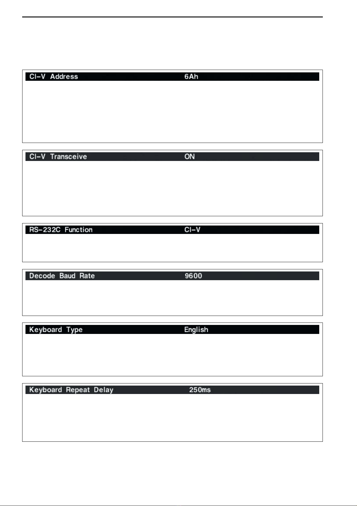
050101 Send/read CI-V transceive set
(0=OFF, 1=ON)
050102 Send/read RS-232C function
(0=CI-V, 1=Decode)
050103 Send/read RS-232C decode
speed (0=300, 1=1200, 2=4800,
3=9600, 4=19200)
050104 Send/read keyboard type
(00=English, 01=Japanese,
02=United Kingdom, 03=French,
04=French (Canadian),
05=German, 06=Portuguese,
07=Portuguese (Brazilian),
08=Spanish, 09=Spanish (Latin
American), 10=Italian)
050105 Send/read keyboard repeat delay
(10=100 msec. to
100=1000 msec.)
050106 Send/read keyboard repeat speed
(0=2.0 cps to 31=30.0 cps)
050107 Send/read IP address set
(0000000000000000=0.0.0.0 to
0255025502550255=255.255.25
5.255)
050108 Send/read subnet mask
(0=0.0.0.0 to 30=255.255.255.252)
050109 Send/read scope indication during
TX (0=OFF, 1=ON)
050110 Send/read scope max. hold
(0=OFF, 1=ON)
050111 Send/read scope center frequen-
cy set (0=Filter center, 1=Carrier
point center, 2=Carrier point cen-
ter (Abs. Freq.))
Command Sub command Description
1A 050112 Send/read waveform color for
receiving signal
(see p. 14-10 for details)
050113 Send/read waveform color for
max. hold
(see p. 14-10 for details)
050114 Send/read scope sweep speed
for ±2.5 kHz span
(0=Slow, 1=Mid., 2=Fast)
050115 Send/read scope sweep speed
for ±5 kHz span
(0=Slow, 1=Mid., 2=Fast)
050116 Send/read scope sweep speed
for ±10 kHz span
(0=Slow, 1=Mid., 2=Fast)
050117 Send/read scope sweep speed
for ±25 kHz span
(0=Slow, 1=Mid., 2=Fast)
050118 Send/read scope sweep speed
for ±50 kHz span
(0=Slow, 1=Mid., 2=Fast)
050119 Send/read scope sweep speed
for ±100 kHz span
(0=Slow, 1=Mid., 2=Fast)
050120 Send/read scope sweep speed
for ±250 kHz span
(0=Slow, 1=Mid., 2=Fast)
050121 Send/read scope edge frequen-
cies for 0.03 to 1.60 MHz band
(see p. 14-10 for details)
050122 Send/read scope edge frequen-
cies for 1.60 to 2.00 MHz band
(see p. 14-10 for details)
050123 Send/read scope edge frequen-
cies for 2.00 to 6.00 MHz band
(see p. 14-10 for details)
050124 Send/read scope edge frequen-
cies for 6.00 to 8.00 MHz band
(see p. 14-10 for details)
050125 Send/read scope edge frequen-
cies for 8.00 to 11.00 MHz band
(see p. 14-10 for details)
050126 Send/read scope edge frequen-
cies for 11.00 to 15.00 MHz band
(see p. 14-10 for details)
050127 Send/read scope edge frequen-
cies for 15.00 to 20.00 MHz band
(see p. 14-10 for details)
050128 Send/read scope edge frequen-
cies for 20.00 to 22.00 MHz band
(see p. 14-10 for details)
050129 Send/read scope edge frequen-
cies for 22.00 to 26.00 MHz band
(see p. 14-10 for details)
050130 Send/read scope edge frequen-
cies for 26.00 to 30.00 MHz band
(see p. 14-10 for details)
050131 Send/read scope edge frequen-
cies for 30.00 to 45.00 MHz band
(see p. 14-10 for details)
050132 Send/read scope edge frequen-
cies for 45.00 to 60.00 MHz band
(see p. 14-10 for details)
050133 Send/read auto voice monitor set
(0=OFF, 1=ON)

14-7
DDCommand table (continued)
14
CONTROL COMMAND
Command Sub command Description
1A 050134 Send/read voice memory short
play time (3=3 sec. to 10=10 sec.)
050135 Send/read voice memory normal
record time
(5= 5 sec. to 15=15 sec.)
050136 Send/read contest number style
(0=Normal, 1=190→ANO,
2=190→ANT, 3=90→NO,
4=90→NT)
050137 Send/read count up trigger chan-
nel (1=M1, 2=M2, 3=M3, 4=M4)
050138 Send/read present number
(1–9999)
050139 Send/read CW keyer repeat time
(1=1 sec. to 60=60 sec.)
050140 Send/read CW keyer dot/dash
ratio (28=1:1:2.8 to 45=1:1:4.5)
050141 Send/read rise time (0=2 msec.,
1=4 msec., 2=6 msec.,
3=8 msec.)
050142 Send/read paddle polarity
(0=Normal, 1=Reverse)
050143 Send/read keyer type (0=Straight,
1=Bug-key, 2=ELEC-Key)
050144 Send/read mic. up/down keyer set
(0=OFF, 1=ON)
050145 Send/read RTTY decode USOS
(0=OFF, 1=ON)
050146 Send/read RTTY decode new line
code (0=CR,LF,CR+LF,
1=CR+LF)
050147 Send/read RTTY diddle (0=OFF,
1=Blank, 2=Letter)
050148 Send/read RTTY TX USOS
(0=OFF, 1=ON)
050149 Send/read RTTY auto CR+LF by
TX (0=OFF, 1=ON)
050150 Send/read RTTY time stamp set
(0=OFF, 1=ON)
050151 Send/read clock selection for time
stamp (0=Local time, 1=Clock 2)
050152 Send/read frequency stamp
(0=OFF, 1=ON)
050153 Send/read received text font color
(see p. 14-10 for details)
050154 Send/read transmitted text font
color (see p. 14-10 for details)
050155 Send/read time stamp text font
color (see p. 14-10 for details)
050156 Send/read text font color in TX
buffer (see p. 14-10 for details)
050157 Send/read PSK time stamp set
(0=OFF, 1=ON)
050158 Send/read clock selection for time
stamp (0=Local time, 1=Clock 2)
050159 Send/read frequency stamp
(0=OFF, 1=ON)
050160 Send/read received text font color
(see p. 14-10 for details)
050161 Send/read transmitted text font
color (see p. 14-10 for details)
050162 Send/read time stamp text font
color (see p. 14-10 for details)
050163 Send/read text font color in TX
buffer (see p. 14-10 for details)
Command Sub command Description
1A 050164 Send/read scan speed
(0=Low, 1=High)
050165 Send/read scan resume
(0=OFF, 1=ON)
050166 Send/read antenna selection for
0.03 to 1.60 MHz band
(see p. 14-10 for details)
050167 Send/read antenna selection for
1.60 to 2.00 MHz band
(see p. 14-10 for details)
050168 Send/read antenna selection for
2.00 to 6.00 MHz band
(see p. 14-10 for details)
050169 Send/read antenna selection for
6.00 to 8.00 MHz band
(see p. 14-10 for details)
050170 Send/read antenna selection for
8.00 to 11.00 MHz band
(see p. 14-10 for details)
050171 Send/read antenna selection for
11.00 to 15.00 MHz band
(see p. 14-10 for details)
050172 Send/read antenna selection for
15.00 to 20.00 MHz band
(see p. 14-10 for details)
050173 Send/read antenna selection for
20.00 to 22.00 MHz band
(see p. 14-10 for details)
050174 Send/read antenna selection for
22.00 to 26.00 MHz band
(see p. 14-10 for details)
050175 Send/read antenna selection for
26.00 to 30.00 MHz band
(see p. 14-10 for details)
050176 Send/read antenna selection for
30.00 to 45.00 MHz band
(see p. 14-10 for details)
050177 Send/read antenna selection for
45.00 to 60.00 MHz band
(see p. 14-10 for details)
050178 Send/read antenna temporary
memory set (0=OFF, 1=ON)
050179 Send/read antenna selection
(0=OFF, 1=Manual, 2=Auto)
050180 Send/read usage for ANT2
(0=OFF, 1=TX/RX)
050181 Send/read usage for ANT3
(0=OFF, 1=TX/RX)
050182 Send/read usage for ANT4
(0=OFF, 1=TX/RX, 2= RX)
050183 Send/read VOX delay (0=0.0 sec.
to 20=2.0 sec.)
050184 Send/read VOX voice delay
(0=OFF, 1=Short, 2=Long)
050185 Send/read NB depth (0=1 to 9=10)
050186 Send/read NB width
(0=0 to 255=255)
050187 Send/read screen saver set
(0=OFF, 1=15 min., 2=30 min.,
3=60 min.)
050188 Set/read screen saver type
(0=Bound, 1=Rotation, 2=Twist)
06 Send/read DATA mode with filter
set (see p. 14-10 for detail)

16-1
UPDATING THE FIRMWARE Section 16
■General ………………………………………………………………… 16-2
■Caution ………………………………………………………………… 16-2
■Preparation …………………………………………………………… 16-3
DFirmware and firm utility …………………………………………… 16-3
DFile downloading …………………………………………………… 16-3
■Firmware update— CF memory card ……………………………… 16-4
■Firmware update— PC ……………………………………………… 16-6
DConnections ………………………………………………………… 16-6
DIP address setting ………………………………………………… 16-7
DUpdating from the PC ……………………………………………… 16-8

16-2
■General
The IC-7800’s firmware can be updated if desired.
By updating the firmware, new function(s) can be
added and the improvement of performance parame-
ters can be made.
2 ways of firmware update are available; one is using
the CF memory card, and the other is using a PC.
You can choose either way according to your PC con-
dition.
• When only one PC that is connected to internet is
available
➥Refer to ■Preparation (p. 16-3) and ■Firmware
update— CF memory card (p. 16-4)
• When two or more PCs that are connected to inter-
net are available and they are connected to the LAN
(Local Area Network)
➥Refer to ■Preparation (p. 16-3) and either
■Firmware update— PC (p. 16-6) or
■Firmware update— CF memory card (p. 16-4)
Ask your dealer or distributor about how to update the
firmware if you have no PC.
■Caution
RCAUTION!: NEVER turn the transceiver power OFF
while updating the firmware.
You can turn the transceiver power OFF only when the
transceiver displays that rebooting is required.
If you turn the transceiver power OFF, or if a power fail-
ure occurs during updating, the transceiver firmware
will be damaged and you have to send the transceiver
back to the nearest Icom distributor for repair. This type
of repair is out of warranty even if the warranty period
is still valid.
Recommendation!
Backing up the settings and/or memory contents to the
CF memory card before starting the firmware update
is recommended.
Settings and/or memory contents will be lost when the
firmware update is performed.
A memory card reader is required to copy the down-
loaded firmware file.
An Ethernet card/board (10 BASE-T/100 BASE TX
compatible) is required when updating the firmware
from the PC.
Both memory card reader and Ethernet card/board
are not supplied from Icom.
Ask your PC dealer about a memory card reader
and an Ethernet card/board for details.
16 UPDATING THE FIRMWARE

16-3
■Preparation
DDFirmware and firm utility
The latest firmware and the firm utility can be down-
loaded from the Icom home page via the internet. Ac-
cess the following URL to download the firm utility and
the latest firmware.
http://www.icom.co.jp/world/download/index.htm
For updating from the CF memory card
When updating the firmware from the CF memory
card, copy the downloaded firmware data (e.g.
7800_110.dat) to the CF memory card (in “IC-7800” folder)
using a memory card reader (purchased separately from
your PC dealer).
DDFile downloading
qAccess the following URL directly.
http://www.icom.co.jp/world/download/index.htm
• No link is available from the top page.
wRead “Regarding this Download Service” carefully,
then click [AGREE].
eClick “IC-7800” link then click the firmware file link.
rType your name, call sign, IC-7800’s serial number,
etc., then click [SEND].
tClick [Save] in the displayed File Download dialog.
ySelect the desired location that you want to save the
firmware to, then click [Save] in the displayed File
Download dialog.
• File download starts.
uAfter download is completed, extract the file.
• The firmware and the firm utility are compressed in “zip”
format, respectively.
• When updating the transceiver using with the CF mem-
ory card, copy the extracted firmware (e.g.
7800_110.dat) to the CF memory card IC-7800 folder.
• The CF memory card must be formatted with the IC-
7800.
Select the saving
location
Click
Click
Click
Read carefully
16
UPDATING THE FIRMWARE

16-4
■Firmware update—CF memory card
When updating the firmware using with the CF mem-
ory card, no IP address as well as subnet mask set-
tings are necessary.
qCopy the downloaded firmware data into the CF
memory card (“IC-7800” folder).
• The CF memory card must be formatted by the IC-7800.
wInsert the CF memory card into the CF card slot.
ePush [EXIT/SET] several times to close a multi-
function screen, if necessary.
rPush [F-7•SET] to select set mode menu screen.
tPush [F-7•CF CARD] to select CF card set menu.
yPush [F-3•FIRM UP] for 1 sec.
uRead the displayed precaution carefully.
• Push [F-1•Y] or [F-2•Z] to scroll the indication.
• Push [F-7•CANCEL] to cancel the firmware updating.
iAfter you read and agree to all of the precautions,
push [F-6•OK].
• [F-6•OK] appears only when the end of the precaution
is displayed.
• Push [F-7•CANCEL] to cancel the firmware updating.
oPush [F-2•Y] or [F-3•Z] to select the firmware file,
then push [F-4•FIRM UP].
!0 Read the displayed precaution carefully.
!1 If you agree, push [F-6•OK] for 1 sec. to start the
firmware update.
• Push [F-7•CANCEL] to cancel the firmware updating.
!2 While loading the firmware from the CF memory
card, the dialog as at left is displayed.
[F-1•Y]/[F-1•DIR/FILE]
[F-3•FIRM UP]/[F-3•Z]
[F-6•OK]
[F-7•SET]/[F-7•CF CARD]
/[F-7•CANCEL]
[F-2•Z]/[F-2•Y] [F-4•FIRM UP]
[EXIT/SET]
16 UPDATING THE FIRMWARE

16-5
!3 After the firmware loading is completed, the trans-
ceiver starts the update automatically and the dialog
as at left is displayed.
RWARNING!: NEVER turn the IC-7800 power
OFF at this stage.
The transceiver firmware will be damaged.
!4 When the dialog disappears, the precaution as at
left is displayed.
!5 Read the precaution carefully, and then push
[F-6•OK].
• Return to CF card set menu.
!6 Push [POWER] to turn the IC-7800 power OFF,
then ON again.
!7 Depending on the updating, one to four dialog as at
left appears in sequence.
RWARNING!: NEVER turn the IC-7800 power
OFF at this stage.
The transceiver firmware will be damaged.
!8 After the dialog disappears, the firmware updating
is completed and normal operation screen appears.
16
UPDATING THE FIRMWARE

16-6
■Firmware update—PC
DDConnections Connect the IC-7800 and the PC through a LAN (Local
Area Network) as follows.
= ××××
*Purchased separately
to WAN
/Internet network
Ethernet cable*
(Patch cable) to crossover port
•IP address setting example
Hub/Router*
IC-7800 (192.168.100.13)
PC1
(192.168.100.11)
PC2
(192.168.100.12)
PC1
192.168.100.11
255.255.255.0
IP address
Subnet mask
PC2
192.168.100.12
255.255.255.0
IC-7800
192.168.100.13
255.255.255.0
16 UPDATING THE FIRMWARE

16-7
DDIP address setting
IMPORTANT!: A fixed (static) IP address is used for
the IC-7800.
When you connect the IC-7800 to a LAN, ask the
network manager about a usable/assignable IP
address and the subnet mask in advance.
NEVER set the IP address that has already been
used with another device in the network. If the IP
address is duplicated, the network will crash down.
qPush [EXIT/SET] several times to close a multi-
function screen, if necessary.
wPush [F-7•SET] to select set mode menu screen.
ePush [F-5•OTHERS] to select miscellaneous (oth-
ers) set mode.
rPush [F-1•Y]/[F-2•Z] several times to select “IP Ad-
dress” item.
tPush [F-3•Ω≈] to select the desired part then ro-
tate main dial to set the desired or specified IP ad-
dress.
• “192.168.0.1” is the default setting.
yPush [F-2•Z] to select “Subnet Mask” item.
uRotate main dial to set the desired or specified sub-
net mask.
• “255.255.255.0” is the default setting.
iPush [POWER] to turn the transceiver power OFF,
then ON to effect the IP address and subnet mask
settings.
[F-1•Y]
[F-3•Ω≈]
[F-5•OTHERS]
[F-7•SET]
[F-2•Z] [EXIT/SET]
When updating the firmware from the CF memory
card, the following settings are not necessary.
16
UPDATING THE FIRMWARE

16-8
DDUpdating from the PC
qStart up the IC-7800 Firm Utility.
• The window as at left appears.
wRead the caution in the window carefully.
eClick [Yes] if you agree and continue the firmware
updating.
rSelect the firmware file, that has “dat” extension
(e.g.: 7800_110.dat).
• Click […], then select the file, as well as the location.
tType the IC-7800’s IP address into “IC-7800 IP Ad-
dress” text box.
yClick [Start].
uThe window as at left appears.
Read the precaution in the window carefully.
iClick [Yes] if you want to start the firmware update.
Click to start the
firmware update
Click […] to select the firmware file.
Type the IC-7800’s IP address here.
Click to
continue
16 UPDATING THE FIRMWARE

16-9
oThe screen as at left is displayed.
• The following dialog appears in the IC-7800 display.
RWARNING!: NEVER turn the IC-7800 power
OFF at this stage.
The transceiver firmware will be damaged.
!0 Click [OK] to finish the firmware update.
• The “FIRMWARE UPDATING” dialog as above disap-
pears.
!1 Push [POWER] to turn the IC-7800 power OFF,
then ON again.
!2 Depending on the updating, one to four dialogs as
at left appears in the IC-7800 display in sequence.
RWARNING!: NEVER turn the IC-7800 power
OFF at this stage.
The transceiver firmware will be damaged.
!3 After the dialog disappears, the firmware updating
is completed and normal operation screen appears.
Click [OK] to finish the firmware update.
16
UPDATING THE FIRMWARE
Other manuals for IC-7800
10
Table of contents
Other Icom Transceiver manuals

Icom
Icom IC-M87 User manual

Icom
Icom IC-V200T User manual

Icom
Icom IC-9100 User manual

Icom
Icom ID-1 Installation and operating instructions

Icom
Icom IC-M36 User manual

Icom
Icom IC-2720H User manual

Icom
Icom IC-M423 User manual

Icom
Icom IC-A14 Owner's manual

Icom
Icom IC-F4210D Series User manual

Icom
Icom IC-E92D User manual

Icom
Icom IC-F70DT User manual

Icom
Icom IC-M506 User manual

Icom
Icom IC-X2A User manual

Icom
Icom iF3002 User manual

Icom
Icom IC-F6121D-51B User manual

Icom
Icom IC-228A User manual

Icom
Icom IC-F4001 User manual

Icom
Icom IC-F52D User manual

Icom
Icom D-STAR ID-4100A Installation guide

Icom
Icom UltraTech IC-F4GT-4 User manual