Icom IC-F51V User manual

INSTRUCTION MANUAL
UHF TRANSCEIVER
iF61V
VHF TRANSCEIVER
iF51V

i
IMPORTANT
READ ALL INSTRUCTIONS carefully and completely before
using the transceiver.
SAVE THIS INSTRUCTION MANUAL— This instruction
manual contains important operating instructions for the IC-F51V
vhf transceiver and IC-F61V uhf transceiver.
EXPLICIT DEFINITIONS
WORD DEFINITION
RWARNING Personal injury, fire hazard or electric shock
may occur.
NOTE If disregarded, inconvenience only. No risk
of personal injury, fire or electric shock.
CAUTION Equipment damage may occur.
OPERATING NOTES
• When transmitting with a portable radio, hold the radio in a vertical
position with its microphone 5 to 10 cm away from your mouth. Keep
the antenna at least 2.5 cm from your head and body.
• If you wear a portable two-way radio on your body, ensure that the
antenna is at least 2.5 cm from your body when transmitting.
Icom, Icom Inc. and the logo are registered trademarks of Icom Incorpo-
rated (Japan) in the United States, the United Kingdom, Germany, France,
Spain, Russia and/or other countries.

PRECAUTIONS
RWARNING! NEVER hold the transceiver so that the antenna is
very close to, or touching exposed parts of the body, especially the face
or eyes, while transmitting. The transceiver will perform best if the micro-
phone is 5 to 10 cm away from the lips and the transceiver is vertical.
RWARNING! NEVER operate the transceiver with a headset or
other audio accessories at high volume levels.
RCAUTION! NEVER short the terminals of the battery pack.
RCAUTION! NEVER connect the transceiver to a power source other
than the BP-226 or BP-227. Such a connection will ruin the transceiver.
RCAUTION! NEVER use non-Icom battery packs/chargers to pre-
vent the loss of the transceiver’s good performance and warranty.
DO NOT push the PTT when not actually desiring to transmit.
DO NOT use or place the transceiver in direct sunlight or in areas with
temperatures below –25°C or above +55°C; except for China. (Below
–30°C or above +60°C for China.)
DO NOT modify the transceiver for any reason.
DO NOT operate the transceiver near unshielded electrical blasting
caps or in an explosive atmosphere. The IC-F51V/F61V series transceiv-
ers are not the explosion-proof construction.
MAKE SURE the flexible antenna and battery pack are securely at-
tached to the transceiver, and that the antenna and battery pack are dry
before attachment. Exposing the inside of the transceiver to water will
result in serious damage to the transceiver.
BE CAREFUL! The IC-F51V/F61V series transceivers employ water-
proof construction, which corresponds to IPX7 of the international standard
IEC 60529 (2001), 1 m depth for 30 minutes. However, once the transceiver
has been dropped, waterproofing cannot be guaranteed due to the fact that
the transceiver may be cracked, or the waterproof seal damaged, etc.
Icom optional equipment is designed for optimal performance when
used with this transceiver. We are not responsible for the transceiver
being damaged or any accident caused when using non-Icom optional
equipment.
ii

TABLE OF CONTENTS
iii
IMPORTANT....................................................................................................i
EXPLICIT DEFINITIONS................................................................................. i
OPERATING NOTES.......................................................................................i
PRECAUTIONS.............................................................................................. ii
TABLE OF CONTENTS................................................................................. iii
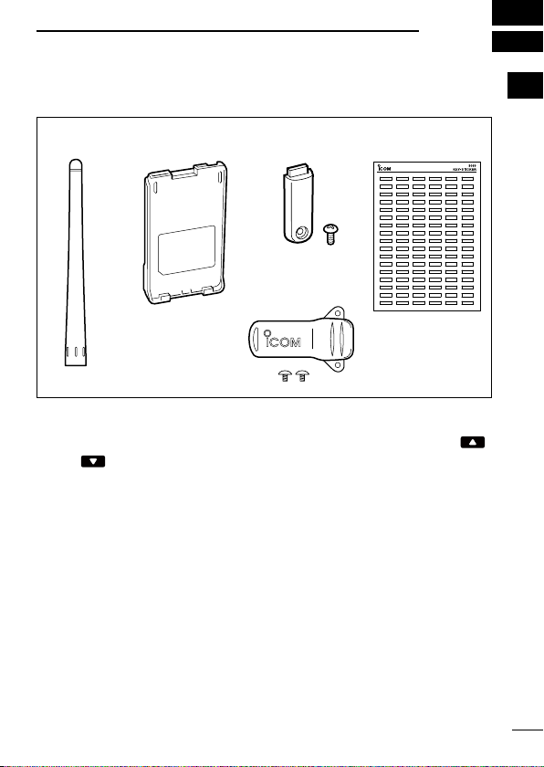
1 ACCESSORIES....................................................................................1–3
■ Supplied accessories ............................................................................1
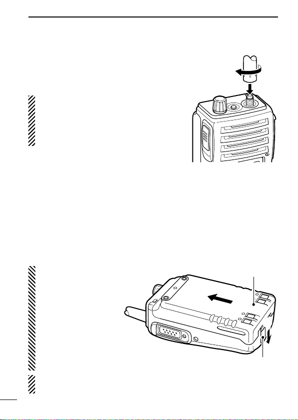
■ Accessory attachments .........................................................................2
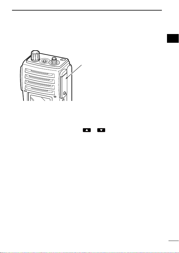
2 PANEL DESCRIPTION.......................................................................4–13
■ Front, top and side panels.....................................................................4
■ Function display ....................................................................................6
■ Programmable function keys.................................................................8
3 BASIC OPERATION.........................................................................14–23
■ Turning power ON ...............................................................................14
■ Channel selection................................................................................14
■ Call procedure.....................................................................................15
■ Receiving and transmitting..................................................................16
■ User set mode.....................................................................................20
■Emergency transmission.....................................................................21
■ Scrambler function ..............................................................................21
■Stun function .......................................................................................21
■ Recording function (Depends on the version).......................................22
4 BATTERY CHARGING ..................................................................... 24–31
■ Caution................................................................................................24
■ Optional battery chargers....................................................................27
5 BATTERY CASE.....................................................................................32
■ Optional battery case (BP-226)...........................................................32
6 SPEAKER-MICROPHONE...............................................................34–35
■ Optional HM-168 description...............................................................34
■ Attachment ..........................................................................................35
7 SWIVEL BELT CLIP .........................................................................36–37
■ MB-86 contents ...................................................................................36
■ Attaching .............................................................................................36
■ Detaching ............................................................................................37
8 OPTIONS..........................................................................................38–41
9 DOC..................................................................................................42–43

1
1
ACCESSORIES
1
2
3
4
5
6
7
8
9
10
11
12
13
14
15
16
17
18
19
20
■Supplied accessories
*There are no names on the programmable function keys since
the functions can be freely assigned to [P0] to [P3], [Red], [ ]
and [ ] keys.
Attach the supplied key stickers above the appropriate keys for
easy recognition of that key’s assigned function.
Battery packAntenna
Belt clip
Key sticker*Jack cover

2
1ACCESSORIES
■Accessory attachments
DFlexible antenna
Connect the supplied flexible antenna
to the antenna connector.
CAUTION!
•
NEVER HOLD the antenna when
carrying the transceiver.
•Transmitting without an antenna
may damage the transceiver.
DBattery pack
To attach the battery pack:
Slide the battery pack on the back of the transceiver in the direc-
tion of the arrow (q), then lock it with the battery release button.
• Slide the battery pack until the battery release button makes a ‘click’
sound.
To release the battery pack:
Push the battery release button in the direction of the arrow (w)
as shown below. The battery pack is then released.
NOTE: Keep the battery pack terminals clean. It’s a good idea
to clean the battery pack terminals once a week.
q
w
Battery pack
Battery release button
NEVER release or at-
tach the battery pack
when the transceiver
is wet or soiled. This
may result water or
dust getting into the
transceiver/battery
pack and may result
in the transceiver be-
ing damaged.

3
1
ACCESSORIES
1
2
3
4
5
6
7
8
9
10
11
12
13
14
15
16
17
18
19
20
DJack cover
Attach the jack cover when the optional equipment is not used.
DBelt clip
Attach the belt clip to the back of the transceiver with the supplied
screws.
Supplied screws
w
Jack cover
[SP MIC] jack
Screw
q
e
r
To attach the jack cover:
qInsert the jack cover into the
[SP MIC] jack.
wTighten the screw.
To detach the jack cover:
eUnscrew the screw using a
phillips screwdriver.
rDetach the jack cover for the
optional equipment connec-
tion.

4
2PANEL DESCRIPTION
■Front, top and side panels
qVOLUME CONTROL [VOL]
Turns power ON and adjusts the audio level.
wRED BUTTON
The desired function can be assigned by your dealer. (p. 8)
eANTENNA CONNECTOR
Connects the supplied antenna. (p. 2)
Microphone
Function display
(p. 6)
w
e
r
t
y
u
q
iSpeaker

5
2
PANEL DESCRIPTION
2
rEXTERNAL SPEAKER-MICROPHONE JACK [SP MIC]
Connects the optional speaker-microphone, etc.
tDEALER-PROGRAMMABLE KEYS [P0] to [P3]
The desired functions can be assigned independently by your
dealer. (p. 8)
yCH UP AND DOWN KEYS [ ]/[ ]
Push to select an operating channel, etc.
*Desired functions can be assigned independently by your dealer.
(p. 8)
uTRANSMIT/BUSY INDICATOR
Lights red while transmitting; lights green while receiving a sig-
nal, or when the squelch is open.
iPTT SWITCH [PTT]
➥Push and hold to transmit; release to receive.
➥When the recording function is activated, TX voice message
can be recorded while pushing and holding [PTT]. (p. 22)
[SP MIC] jack cover
NOTE: KEEP the [SP MIC]
jack cover attached to the
transceiver when the optional
equipment is not used.
(See p. 3 for details)

6
2PANEL DESCRIPTION
■Function display
q RECORD INDICATOR
➥Appears when an unread message is in the memory.
➥Blinks while recording.
w LOW POWER INDICATOR
Appears when low output power is selected.
eAUDIBLE INDICATOR
➥
Appears when the channel is in the ‘audible’ (unmute) condition.
➥ Appears when the specified 5-tone/BIIS*1/MDC*2code is re-
ceived.
rCOMPANDER INDICATOR
Appears when the compander function is activated.
tKEY LOCK INDICATOR
Appears when the key lock function is activated.
ySCRAMBLER INDICATOR
Appears when the voice scrambler function is activated.
uBELL INDICATOR
Appears/blinks when the specific 5-tone/BIIS*1/MDC*2code is
received, according to the pre-programming.
q t iuyrew
o

7
2
PANEL DESCRIPTION
2
iBATTERY INDICATOR
Appears or blinks when the battery power decreases to a speci-
fied level.
oALPHANUMERIC DISPLAY
Displays an operating channel number, channel names, Set
mode contents, DTMF code, etc.
*1BIIS operation only
*2MDC operation only

8
2PANEL DESCRIPTION
■Programmable function keys
The following functions can be assigned to [P0], [P1], [P2], [P3],
[Red], [ ] and [ ] programmable function keys.
Consult your Icom dealer or system operator for details concern-
ing your transceivers programming.
If the programmable function names are bracketed in the following
explanations, the specific key is used to activate the function de-
pends on programming.
CH UP AND DOWN KEYS
➥Push to select an operating channel.
➥Push to select a transmit code channel after pushing [TX Code
CH Select].
➥Push to select a DTMF channel after pushing [DTMF Autodial].
➥Push to select a scan group after pushing and holding [Scan A
Start/Stop]/[Scan B Start/Stop].
ZONE SELECT KEY
Push this key, then select the desired zone using [CH Up]/[CH
Down].
What is a “zone”?—The desired channels are assigned into a
zone according to the intended use for grouping. For example,
‘Staff A’ and ‘Staff B’ are assigned into a “Business” zone, and
‘John’ and ‘Cindy’ are assigned into a “Private” zone.
SCAN A START/STOP KEY
➥This key’s operation depends on the Power ON Scan setting.
When the power ON scan function is turned OFF;
Push to start and cancel scanning operation.
When the power ON scan function is turned ON;
Push to pause scanning, then resumes scanning after a speci-
fied time period has passed.
➥Push and hold this key for 1 sec. to indicate the scan group,
then select the desired scan group using [CH Up]/[CH Down].

9
2
PANEL DESCRIPTION
2
SCAN B START/STOP KEY
➥Push to start and cancel scanning operation. Scan resumes
after a specified time period has passed when scan is cancelled
except for this key.
➥Push and hold this key for 1 sec. to indicate the scan group,
then select the desired scan group using [CH Up]/[CH Down].
SCAN ADD/DEL (TAG) KEY
➥Push to add or delete the selected channel to/from the scan
group.
1. Push to indicate the scan group, then push [CH Up] or [CH Down]
to select the desired group.
2. Push to add or delete the channel to/from the selected scan
group.
3. Push and hold for 1 sec. to exit the scan group selection mode.
➥Push this key while scan is paused (a signal is detected) on
a channel (except for priority channel,) the channel is cleared
from the scan group.
Depending on the setting, the cleared channel is added to
the scan group again after the scan is cancelled. (Nuisance
Delete function)
PRIORITY CHANNEL KEYS
➥Push to select Priority A or Priority B channel.
➥Push and hold [Prio A (Rewrite)] or [Prio B (Rewrite)] to set the
operating channel as the Priority A or Priority B channel.
MR-CH 1/2/3/4 KEYS
Push to select the memory channel 1 to 4 directly.
LOCK KEY
Push and hold to toggle the key lock function ON or OFF.
•
All programmable keys except the followings are electronically locked
when the key lock function is activated: [PTT], [Light], [Lone Worker], [Sur-
veillance], [Call] (incl. Call A and Call B), [Moni(Audi)] and [Emergency].

10
2PANEL DESCRIPTION
MONITOR KEY
Activates one of (or two of) the following functions on each chan-
nel independently:
• Push and hold to un-mute the channel (audio is emitted; ‘Audible’
condition).
• Push to mute the channel (sets to ‘Inaudible’ only).
• Push after the communication is finished to send a ‘reset code’. (BIIS
operation only)
NOTE: The un-mute condition (‘Audible’ condition) may auto-
matically return to the mute condition (‘Inaudible‘ condition)
after a specified period.
LIGHT KEY
Push to turn the backlight ON for about 5 sec. even if the backlight
function is turned OFF in user set mode.
LONE WORKER KEY
Push to turn the Lone Worker function ON or OFF.
• If the Lone Worker function is activated, the Emergency function is
automatically turned ON after the specified time period has passed
with no operation is performed.
HIGH/LOW KEY
Push to select the transmit output power temporarily or perma-
nently, depending on the pre-setting.
• Ask your dealer for the output power level for each selection.
C.TONE CHANNEL ENTER KEY
Push to enter the continuous tone channel selection mode, and
push [CH Up]/[CH Down] to change the tone frequency/code set-
ting. The selected channel remains set as the continuous tone
channel until another channel is designated as such.

11
2
PANEL DESCRIPTION
2
TALK AROUND KEY
Push to turn the talk around function ON and OFF.
• The talk around function equalizes the transmit frequency to the re-
ceive frequency for transceiver-to-transceiver communication.
WIDE/NARROW KEY
Push to toggle the IF bandwidth between wide and narrow.
• The wide passband width can be selected from 25.0 or 20.0 kHz
using the CS-F50V cloning software. Ask your dealer for details.
DTMF AUTODIAL KEY
➥Push to enter the DTMF channel selection mode. Then select
the desired DTMF channel using [CH Up]/[CH Down].
➥After selecting the DTMF channel, push again to transmit the
selected DTMF code.
DTMF RE-DIAL KEY
Push to transmit the last-transmitted DTMF code.
• TX memories are cleared after turning the transceiver OFF.
CALL KEYS
Push to transmit a 5-tone/BIIS ID code.
• Call transmission is necessary before calling another station depend-
ing on your signalling system.
• [Call A] and/or [Call B] may be available when your system employs
selective ‘Individual/Group’ calls. Ask your dealer which call is as-
signed to each key.
SURVEILLANCE KEY
Push to turn the surveillance function ON or OFF.
When this function is turned ON, the beep is not emitted and the
LCD backlight and the LED indicator do not light when a signal is
received or a key is pushed.

12
2PANEL DESCRIPTION
EMERGENCY KEYS
Push and hold to transmit the emergency call.
• The emergency call transmits with beeps; the display does not
change.
• The transceiver can transmit the emergency call silently or with the
display changes depending on the pre-setting. Ask your dealer for
details.
• If you want to cancel the emergency call, push and hold the key
again before transmitting the call.
• The emergency call is transmitted one time only or repeatedly until
receiving a control code, depending on the pre-setting.
TX CODE ENTER KEY
Push to enter the TX code edit mode. Then set the desired digit
using [CH Up]/[CH Down]. (p. 19)
TX CODE CHANNEL SELECT KEY
➥Push to enter the TX code channel selection mode. Then select
the desired channel using [CH Up]/[CH Down]. (p. 18)
➥While in the TX code channel selection mode, push and hold for
1 sec. to enter the TX code edit mode. Then set the desired digit
using [CH Up]/[CH Down]. (p. 19)
TX CODE CHANNEL UP/DOWN KEYS
Push to select a TX code channel directly.
ID-MR SELECT KEY
➥Recalls detected ID codes.
• Push this key, then push [CH Up]/[CH Down] for selection.
• Up to 5 ID’s are memorized.
➥Push and hold to erase the selected memorized ID’s.
VOICE SCRAMBLER FUNCTION
Push to turn the voice scrambler function ON and OFF.

13
2
PANEL DESCRIPTION
1
2
3
4
5
6
7
8
9
10
11
12
13
14
15
16
17
18
19
20
COMPANDER KEY
Push to turn the compander function ON and OFF.
The compander function reduces noise components from the
transmitting audio to provide clearer communication.
USER SET MODE KEY
➥Push and hold to enter user set mode.
• While in user set mode, push this key to select an item, and push
[CH Up]/[CH Down] to change the value or condition.
➥Push and hold this key again to exit user set mode.
• User set mode is also available via the ‘Power ON function’.
Please refer to p. 20 also.
PLAYBACK KEY (p. 23)
➥Push to playback the recorded messages in sequence, starting
with the latest one.
• A short beep is emitted after playing back each message.
• A long beep is emitted after playing back all messages.
• An error beep is emitted when there are no messages in the
memory.
➥While playing back the message, push and hold for 1 sec. to
delete the selected message.
PLAYBACK/REC KEY (pgs. 22, 23)
➥Push to playback the recorded messages in sequence from the
newest one.
• A short beep is emitted after playing back each message.
• A long beep is emitted after playing back all messages.
• “NO REC” is displayed when no message is in the memory.
➥Push and hold for 1 sec. to start recording. Push again to stop
recording.
➥While playing back the message, push and hold for 1 sec. to
delete the selected message.

14
3BASIC OPERATION
■Turning power ON
qRotate [VOL] to turn power ON.
• When the opening vibration function is turned ON, the transceiver
vibrates for 2 sec. Ask your dealer for details.
wIf the transceiver is programmed for a start up passcode, input
digit codes as directed by your dealer.
• The keys in the table below can be used for password input:
• The transceiver detects numbers in the same block as identical.
Therefore “01234” and “56789” are the same.
KEY
NUMBER 0
5
4
9
3
8
2
7
1
6
or
eWhen the “PASSWORD” indication does not clear after input-
ting 4 digits, the input code number may be incorrect. Turn the
power off and start over in this case.
■Channel selection
Several types of channel selections are available. Methods may
differ according to your system set up.
NON-ZONE TYPE:
Push [CH Up]/[CH Down] to select the desired operating channel
in sequence; or, push one of [MR-CH 1] to [MR-CH 4] to select a
channel directly.
ZONE TYPE:
Push [Zone] then push [CH Up]/[CH Down] to select the desired zone.
AUTOMATIC SCAN TYPE:
Channel setting is not necessary for this type. When turning the
power ON, the transceiver automatically starts scanning. Scanning
stops when receiving a call.

15
3
BASIC OPERATION
1
2
3
4
5
6
7
8
9
10
11
12
13
14
15
16
17
18
19
20
■Call procedure
When your system employs tone signalling (excluding CTCSS and
DTCS), this call procedure may be necessary prior to voice trans-
mission. The tone signalling employed may be a selective calling
system which allows you to call specific station(s) only and prevent
unwanted stations from contacting you.
qSelect the desired TX code channel or 5-tone code according to
your System Operator’s instructions.
• This may not be necessary depending on programming.
• Refer to pgs. 18, 19 for selection.
wPush [Call] (assigned to one of the dealer programmable keys).
eAfter transmitting, the remainder of your communication can be
carried out in the normal fashion.
Selective calling Non-selective calling

16
3BASIC OPERATION
■Receiving and transmitting
NOTE: Transmitting without an antenna may damage the trans-
ceiver. See p. 2 for antenna attachment.
Receiving:
qRotate [VOL] to turn power ON.
wPush [CH Up] or [CH Down] to select a channel.
eWhen receiving a call, adjust the audio output level to a com-
fortable listening level.
Transmitting:
Wait for the channel to become clear to avoid interference.
qWhile pushing and holding [PTT], speak into the microphone at
a normal voice level.
• When a tone signalling system is used, the call procedure de-
scribed at the previous page may be necessary.
wRelease [PTT] to return to receive.
IMPORTANT: To maximize the readability of your signal;
1. Pause briefly after pushing [PTT].
2. Hold the microphone 5 to 10 cm from your mouth, then
speak into the microphone at a normal voice level.
Other manuals for IC-F51V
1
This manual suits for next models
1
Table of contents
Other Icom Transceiver manuals

Icom
Icom IC-F3360D Series User manual

Icom
Icom IC-255A User manual

Icom
Icom IC-705 Setup guide

Icom
Icom IC-202E User manual

Icom
Icom UX-S92A User manual

Icom
Icom IC-F3262DT User manual

Icom
Icom IC-F3201DEX Installation guide

Icom
Icom IC-E92D User manual

Icom
Icom IC-M304 User manual

Icom
Icom IC-M88 User manual