icoms TMA 3B3 User manual

TMA 3B3
User guide (V3.5.2)
1 CONTENTS
1 CONTENTS.............................................................................................................................................................1
2 FIGURES.................................................................................................................................................................2
3 INTRODUCTION.....................................................................................................................................................4
4 PRODUCT DESCRIPTION........................................................................................................................................4
4.1 Delivery .............................................................................................................................................................4
4.2 Labels location ..................................................................................................................................................4
4.2.1 Identification label ....................................................................................................................................4
4.2.2 Radar serial number..................................................................................................................................4
5 SAFETY PRECAUTIONS...........................................................................................................................................5
6 THEORY OF OPERATION........................................................................................................................................5
7 LED indicator.........................................................................................................................................................5
8 CABLING ................................................................................................................................................................6
9 INSTALLATION GUIDE............................................................................................................................................6
9.1 Direction detection ...........................................................................................................................................6
9.2 Choice of the installation location ....................................................................................................................6
9.3 Physical installation...........................................................................................................................................6
9.4 Detection precision in function of the installation height, offset and width of bicycle path...........................7
10 ADDITIONAL CABINET .........................................................................................................................................10
10.1 Functional description ....................................................................................................................................10
10.2 Setup ...............................................................................................................................................................10
11 RADAR SETTINGS.................................................................................................................................................11
11.1 Communication...............................................................................................................................................11
11.2 Configuration of the radar using the IcomSoft TMA-3B3 ...............................................................................11
11.2.1 Tabs.........................................................................................................................................................11
11.2.2 Step 1 –serial communication................................................................................................................12
11.2.3 Step 2 –background configuration.........................................................................................................12
11.2.4 Step 3 –range and speed configuration.................................................................................................12
11.2.5 Step 4 –advanced configuration options ...............................................................................................13
11.2.6 Step 5 –save the settings .......................................................................................................................15
11.2.7 Step 6 –check the detections.................................................................................................................15
11.2.8 Step 7 –close the software.....................................................................................................................16
11.3 Real-time data on HyperTerminal...................................................................................................................16

2
12 DATA FORMAT ....................................................................................................................................................17
12.1 Measurement message:..................................................................................................................................17
12.2 Measurement payload:...................................................................................................................................17
12.3 Day and direction byte:...................................................................................................................................17
12.4 ASCII messages (param 50 100)......................................................................................................................17
12.5 Detection types...............................................................................................................................................18
13 MODEM CONFIGURATION..................................................................................................................................18
13.1 List of most important parameters.................................................................................................................18
13.2 Data format of CSV files sent by the modem..................................................................................................18
14 VANDAL PROOF OPTIONAL HOUSING ................................................................................................................19
15 SOLAR PANEL ......................................................................................................................................................20
16 FAQ......................................................................................................................................................................23
17 TECHNICAL FEATURES.........................................................................................................................................23
17.1 TMA-3B3 .........................................................................................................................................................23
17.2 Modem............................................................................................................................................................23
18 WARRANTY..........................................................................................................................................................24
19 FURTHER INFORMATION ....................................................................................................................................24
19.1 Legal notification.............................................................................................................................................24
19.2 VERSION..........................................................................................................................................................24
19.3 The manufacturer: ..........................................................................................................................................24
2 FIGURES
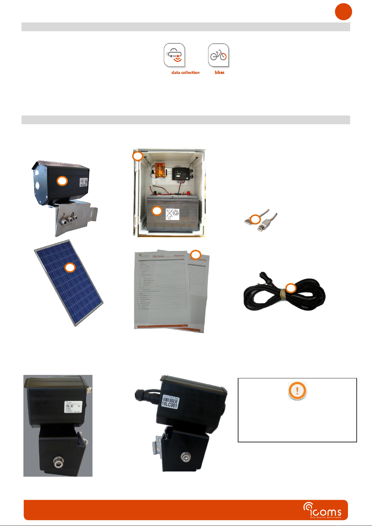
Figure 1: content of the delivery.......................................................................................................................................4
Figure 2: identification label .............................................................................................................................................4
Figure 3 : TMA-3B3 LV radar connector - Weipu SP1712/P9............................................................................................6
Figure 4: installation, general overview............................................................................................................................7
Figure 5: installation, side view.........................................................................................................................................7
Figure 6: detection precision in function of offset (O) and width of bicycle path (W) for an installation height (H) of 2
m 8
Figure 7: detection precision in function of offset (O) and width of bicycle path (W) for an installation height (H) of
2.5 m 9
Figure 8: detection precision in function of offset (O) and width of bicycle path (W) for an installation height (H) of
1.4 m 9
Figure 9: cabinet, outside................................................................................................................................................10
Figure 10: cabinet, inside................................................................................................................................................10
Figure 11: modem...........................................................................................................................................................10
Figure 12: cabinet, backside............................................................................................................................................10

3
Figure 13 : cabinet, power connections..........................................................................................................................10
Figure 14: IcomSoft TMA-3B3 GUI when first opened....................................................................................................11
Screenshot 1: setting the background range..................................................................................................................12
Screenshot 2: detection range configuration .................................................................................................................13
Screenshot 3: object detections displayed on the Graphical User Interface (GUI)........................................................16
Figure 15: vandal proof additional housing - front view.................................................................................................19
Figure 16: vandal proof additional housing - vertical angle adjustment screws............................................................19

4
3 INTRODUCTION
The TMA-3B3 is the combination of a microwave radar and a light emitting sensor, designed for bicycles counting on bicycle
lane. The output consists of a serial interface. The unit can be delivered with a solar panel and with an additional cabinet
containing a battery, a modem and a solar regulator.
4 PRODUCT DESCRIPTION
4.1 DELIVERY
Figure 1: content of the delivery
4.2 LABELSLOCATION
4.2.1 Identification label
4.2.2 Radar serial number
Figure 2: identification label
A
Do not remove the labels
B
D
E
C
F
G

5
5 SAFETY PRECAUTIONS
Only skilled and instructed persons should carry out work with the radar product. Experience and safety procedures in the
following areas may be relevant:
•Working with mains power
•Working with modern electronic and electric equipment
•Working at height
•Working at the roadside or highways
Please follow these safety precautions:
-Make sure the electricity supply is within the range shown on the label and the manual of the product.
-All connections must be made whilst the power supply is switched off.
-Ensure the wiring is correct as shown in the manual before switching on the power supply.
-Never use a damaged radar.
-Opening the outer casing is deemed dangerous and will void all warranties.
-Ensure the radar is mounted correctly and the screws and bolts of both radar and bracket are firmly tightened. The
radar needs to point to the region of interest for proper detection.
-Ensure the radar is configured properly.
6 THEORY OF OPERATION
1. Unpack the unit and check the following items are in the box (please refer to Figure 1, p. 4):
A. Radar/lidar with rear side connectors and mounting bracket
B. Additional cabinet with solar regulator and modem
C. USB AB cable
D. Battery 100 Ah (optional)
E. Solar panel 85 W with mounting bracket (optional)
F. User’s guide
G. Power supply & communication cable
2. Place the unit on the field and align it to the traffic (see title 9, p. 6).
3. Install the additional cabinet (B) on the same pole.
4. Place the battery (D) in the cabinet and connect it.
5. Mount the solar panel (E) according to the instructions (see title 15, p. 18).
6. Connect the cable from the radar to the additional cabinet.
7. Connect the cable from the solar panel to the additional cabinet.
7 LED indicator
The LEDs blink at power up and are then shut off.

6
Figure 3 : TMA-3B3 LV radar
connector - Weipu SP1712/P9
8 CABLING
CAUTION: positive security/fail safe relays - contacts given for powered
radar.
USER’S OUTPUTS
Resistive load: 30 V AC 0.3 A - 60 V DC 0.3 A
REMARKS
•Make sure the plug is fully inserted in the socket and the cap is firmly tightened on the socket.
•Please disconnect the radar from the power source before maintenance intervention.
9 INSTALLATION GUIDE
9.1 DIRECTIONDETECTION
The TMA-3B3 measures in both directions, and associates a + sign for the approaching objects and a –sign for the receeding
ones. We recommend to install the radar so that the approaching direction is the direction with the largest volume of
cyclists.
9.2 CHOICEOFTHEINSTALLATIONLOCATION
•The TMA-3B3 is designed to measure on dedicated bicycle paths only. It is not able to count the bicycles in mixed traffic
situations.
•Select a free-flowing section to perform the counting, where targets are not supposed to stop in the sensor beam. Proximity of
intersections is not advised. A bloc of measurements with the same time stamp corresponds to the case where a target
stopped for some time in the "laser" beam. Currently this is not filtered out and generate a "long" target that is then sliced in so
many bicycles.
•The sensor measures both directions. If the bicycle path is one-direction, install the radar in the way it detects the approaching
direction.
•Max. measurement distance ofthe sensor: about 6 m (angle 45°). This results in a maximum width “D” of 4 m, see Figure 4.
•Max. width of the bicycle path: 4 m, offset included.
•Avoid obstacles like tree branches or leaves in the beam of the sensor.
9.3 PHYSICALINSTALLATION
•Offset: distance between the pole and the near edge of the bicycle lane (perpendicular to the bicycles direction)
•Distance: distance between the pole and the far edge of the bicycle lane (perpendicular to the bicycles direction).
This distance (D) is equal to the Width (W) of the bicycle path plus the Offset (O)
D = W + O
•Height: distance between the ground and the low edge of the radar bracket
LV (12-16 V DC)
PIN nr
Color
Function
1
RED
Power ~ (AC), + (DC)
2
BLUE
N/A
3
BLACK
Power ~(AC), - (DC GND)
4
BROWN
N/A
5
WHITE / PURPLE
COM relay 1
6
GREY
NO relay 1
7
YELLOW
NC relay 1
8
GREEN
N/A
9
PINK /ORANGE
N/A

7
•Recommended installation’ height according to offset, for a 2 m wide bicycle lane and 15° vertical angle:
O(FFSET)
0 m
1 m
2 m
H(EIGHT)
1.4 m
1.75 m
2.10 m
1. Horizontal angle: 45° (towards the bicycles direction)
2. Vertical angle (inclination towards the ground): The light emitting beam must “cut” the cyclists, at the waist level or
higher. An installation at 0° (horizontal installation) is possible.
3. Fix the screws.
Figure 4: installation, general overview
Figure 5: installation, side view
9.4 DETECTIONPRECISIONINFUNCTIONOFTHEINSTALLATIONHEIGHT,OFFSETANDWIDTHOFBICYCLEPATH
The higher the radar is installed, the larger vertical angle of the radar to detect the cyclists and therefore the smaller the
detection Distance (D). Figure 6 shows in green the possible combinations of Offsets and Width at installation height of 2 m for
a high degree of precision (97 % or more). The orange area shows the combinations of Offsets and Width for which the
detection precision will drop below 97 %.
The cyclists must “cut” the light emitting sensor beam in
order to be detected and counted. Please check the
cyclists, particularly the children, who are riding at the
side where the radar is installed are well detected. If
necessary, reduce the height of installation.
D
O
H
W

8
Figure 6: detection precision in function of offset (O) and width of bicycle path (W) for an installation height (H) of 2 m
The detector beam needs to point towards the head or the body of the cyclists, not the legs. Therefore, when placing the
detector higher, the light beam of the detector needs to be directed towards the ground at a larger angle. The angle and
therefore the maximum distance of detection is therefore a function of the height of the installation, the Offset (O) and the
Width (W) of the bicycle path.
The maximum detection Distance D as shown in Figure 4 is 4 m. At an Offset value of zero meter, the maximum width of the
bicycle path is equal to 4 meters, which is in such particular case equal to the maximum Distance D.
Assuming that the minimum height of the saddle is 1m and that the minimum height of the cyclists’ heads is 1.6m, the
maximum Width W of the bicycle path with Offset zero is 1.25 m as shown in Figure 6 for an installation height at 2m.
For an installation height at 2.5m, the maximum Width W of the bicycle path with Offset zero is 0.35 m as shown in Figure 7.
For an installation height at 1.4 m, the maximum Width W of the bicycle path with Offset zero is 4 m as shown in Figure 8.

9
Figure 7: detection precision in function of offset (O) and width of bicycle path (W) for an installation height (H) of 2.5 m
Figure 8: detection precision in function of offset (O) and width of bicycle path (W) for an installation height (H) of 1.4 m

10
10 ADDITIONAL CABINET
10.1 FUNCTIONALDESCRIPTION
The cabinet includes a modem (1), an optional battery (3) and a solar regulator (2).
Figure 9: cabinet, outside
Figure 10: cabinet, inside
Figure 11: modem
1: modem
2: solar regulator
3: battery (12 V 100 Ah, optional)
4: modem antenna
5: modem socket to the radar
6: modem configuration socket
7: SIM card slot
8: radar socket
9: power socket
10: clamps
10.2 SETUP
1. Install the cabinet at the foot of the pole, under the TMA-3B3. Insert collars with the right diameter in the clamps (10)
on the backside of the cabinet.
2. Insert a SIM card in the slot (Figure 10, p. 10, mark 7).
3. Plug the solar panel (see Title 11) or the power source for the battery (12 V) in the below connector backside, (Figure 10
& Figure 12, p. 10, mark 9) :
4. Plug the radar in the upper connector backside (Figure 10 & Figure 12, p. 10, mark 8)
Figure 12: cabinet, backside
Figure 13 : cabinet, power connections
8
9
10
10
1
2
3
4
5
7
6
8
9

11
11 RADAR SETTINGS
11.1 COMMUNICATION
•The TMA-3B3 can be configured by serial communication (115200 bauds 8N1).
•It needs to be disconnected from the modem and connected to a PC equipped with a serial port (or via an USB-Serial (RS-232)
adapter).
•Please note that the modem should be reconnected to the TMA-3B3 after its configuration.
11.2 CONFIGURATIONOFTHERADARUSINGTHEICOMSOFTTMA-3B3
Firstly, power on the radar.
Secondly, launch the software by executing the tma3b3config_Vx.y.z.exe program (x, y and z refer to the version numbers). It will
open a DOS window and will take some time to launch the Graphical User Interface (GUI), please be patient while the software starts
up.
Figure 14: IcomSoft TMA-3B3 GUI when first opened
11.2.1 Tabs
There are two tabs:
•The “Background config” tab, used to configure the background of the lidar.
This tab shows the “raw” range (the true range measured by the lidar). The limit must be fixed to reject objects that are farther
away than this limit.
•The “Hybrid config” tab, used to configure the limits of the bike lane (in speed and range).
This tab shows the range (top) and the speed (bottom) of the detected objects. The range here is taken perpendicularly to the
bike lane (that is, taking into account the horizontal installation angle of 45 °).

12
11.2.2 Step 1 –serial communication
Select the serial port your PC uses to communicate with the radar and click “Connect”
11.2.3 Step 2 –background configuration
In the “Background config” tab, set the background limit: The limit (red line) should be set at least 25 cm below the average
range background, see Screenshot 1. This means that the red line needs to be below the blue line. In order to do so, key in the
value on the right field and hit “TAB”.
Once set, send the parameters to the radarby clicking the “Save to TMA-3B3” button. The displayed range in this tab is the
“raw” range, that is the true range measured by the lidar.
Screenshot 1: setting the background range
11.2.4 Step 3 –range and speed configuration
In the “Hybrid config” tab (Screenshot 2), set the min and max range limits for both the lidar and the radar. In this tab, the
displayed ranges are given perpendicular to the bike lane direction. This means thatthe installation angle of 45° is already taken
into account in the calculations and thesettings.
1. First set the min and max range values for the lidar (turquoise lines). The lidar ranges should be close to the ones that
would be measured by tape measure.
2. Then set the radar range (grey lines). The radar ranges should be set at slightly larger values than the lidar limits (typically
about 50 cm), because the range measurement of the radar is a little less precise.
In the same “Hybrid config” tab, set the min and max speed limits. This allows to reject targets under or above typical bicycle
speeds (typically minimum 8 km/h to reject most pedestrian, and maximum 35 km/h to reject cars driving close to the bike
lane).

13
Screenshot 2: detection range configuration
11.2.5 Step 4 –advanced configuration options
11.2.5.1 Maximum bicycle speed setting
The maximum bicycle speed is by default set to 40 km/h. From TMA-3B3 v2.2.3 onwards, it is possible to change the maximum
speed to 55 km/h. The trade-off for a larger maximum speed is a shorter detection distance (D) of maximum 3.3 meters instead
of 4 meters.
To change the maximum bicycle speed, it is necessary to set two parameters. This can be done by setting the following
parameter values in the graphical user interface shown in Screenshot 2 as specified below:
11.2.5.1.1 Standard maximum bicycle speed (default = 40 km/h)
Parameter 282 to value 64
Parameter 283 to value 10
11.2.5.1.2 High maximum bicycle speed (55 km/h)
Parameter 282 to value 32
Parameter 283 to value 5
11.2.5.2 ITC (Intelligent Traffic Control) messages
From v2.2.3 onwards, the TMA-3B3 can be configured to send “ITC” messages in addition to the standard counting messages.
11.2.5.2.1 ITC messages description
ITC messages
•Are meant for traffic management applications in need of messages sent quickly or after a fixed delay after the target has
crossed the laser beam.

14
•Can be separated from the counting messages by looking to the “detection type” field of the message (see “12.5 Detection
types”).
•Are available only for incoming targets (targets that are approaching the detector when they are measured).
•Should not be considered for the counting application of the TMA-3B3 as they will be followed by a standard counting message
corresponding to the same target (immediately, or a few seconds after the fast message).
•Are disactivated by default.
11.2.5.2.2 Activation of the ITC messages
To activate the ITC messages, it is necessary to set the fixed message delay (parameter 298) to a value different from 0, typically 2500
ms. Those values can be set in the graphical user interface shown in Screenshot 2 as specified below:
Parameter 298 to value 2500
To deactivate the ITC messages, set parameter 298 to 0:
Parameter 298 to value 0
11.2.5.3 Dry contact relay
11.2.5.3.1 Description
When switching on the relay feature, the internal relay is activated every time a bicycle is detected.
•The relay can be either linked to counting events or to “ITC” events (fast counting in the incoming direction, see section
11.2.5.2).
•When the relay is linked to counting events:
oOne click of the relay per bicycle counted (one click = temporary closure of the “NO”output).
oThis click occurs when the target is validated by the TMA-3B3. This validation takes place when the target leaves
the radar detection zone (which extends approximately from the installation point up to ~ 8 m from it). Compared
to the cut-off point of the laser beam, approaching targets will therefore be taken into account more quickly than
receding targets. If the radar detection is not validated, the validation of the target seen by the laser is done after a
timeout of 9 seconds.
•When the relay is linked to “ITC” events:
oOne click of the relay per approaching bicycle detected by the TMA-3B3 (one click = temporary closure of the “NO”
output).
oThis click occurs when the target is validated by the TMA-3B3.
•A minimum duration of 100 ms (configurable) during which the state of the relay does not change, is guaranteed for both
"active" and "inactive" times.
•If more targets are detected than the relay can output given the time constraint described above, they are added to a queue
until they can be issued to the relay.
•The size of this queue is fixed at 10 (configurable, parameter 041). If the queue size grows beyond the maximum size,
corresponding targets will be ignored (to allow limitation of the detection rate and as protection against possible abnormal
situations).
•The relay will not be energized in the inactive state (for consumption reasons) but can be configured in positive security if
desired.
•The relay will make a click at start-up (to be able to easily check its operation). All other clicks will take place for counting only.
11.2.5.3.2 Parameter settings
To change the relay parameter settings, use the following parameter settings:
•Relay maximum buffer size (parameter 41)
oMaximum number of events queued in the buffer. If more events happen than can be transmitted or queued, they
the exceeding detection messages are ignored.
oDefault = 10

15
•Relay click duration (parameter 42) in ms
oMinimum time during which the state of the relay does not change. This duration is guaranteed for both "active"
and "inactive" times.
oRange = [0, 65535]
•Detection type (parameter 72)
oRange = [0, 1, 2]
▪0: Inactive relay
▪1: ITC
▪2: Normal counting
oDefault setting = 0 (inactive)
11.2.5.3.3 Advanced relay parameter settings
The advanced relay parameter settings can be changed using the software in expert mode (ask your distributor to access the
expert mode) or by using a HyperTerminal and communicating over a RS-232 serial link.
•Direction of detection for relay activation (parameter 063)
oRange = [0, 1, 2]
▪0: Receding direction
▪1: Approaching direction
▪2: Bi-directional
oDefault setting = 2 (bi-directional)
•Relay state when inactive (param 67)
oRange = [0, 1]
▪0: non-energized relay when inactive (no detection)
▪1: energized relay when inactive (no detection)
oDefault = 0 (non-energized when no detection)
11.2.6 Step 5 –save the settings
Once the limits are set, send them to the radar by clicking the “Save to TMA-3B3” button.
11.2.7 Step 6 –check the detections
Check that the measured radar and lidar objects are properly validated (brown) of rejected (red).
•Laser object are represented by two circles linked by a line segment. Those represent the range and duration of the
corresponding object detected by the lidar.
◦Orange means the object has been validated by the TMA-3B3.
◦Red means the object was rejected. It is displayed to give feedback on the current set of programmed limits.
•Radar objects are represented by a star that represent the range, speed, and estimated time of arrival at the laser
crossing point.
◦Orange means the object has been validated by the TMA-3B3.
◦Red means the object was rejected. It is displayed to give feedback on the current set of programmed limits.

16
•A triangle represents a complete detection.
◦An orange triangle (lidar + radar) represents a complete object. Those triangle objects will be recorded with the
attributes timestamp, speed, length, and range.
◦A grey triangle (lidar) represents a lidar object that could not be associated with a speed. Those objects will be
recorded with the last speed detected.
◦A grey-blue triangle (radar) represents a radar object that could not be associated with a lidar object. Those
objects are not recorded.
Screenshot 3: object detections displayed on the Graphical User Interface (GUI)
The configuration is correct when detected bicycles are shown as orange triangles.
i. Cars and other moving objects beyond the bicycle path should not be detected and therefore only
generate red triangles.
ii. If the bicycles are measured in both directions, check on the lower graph that both directions are
taken in account (positive speed = approaching bicycles, negative speed = receding bicycles).
11.2.8 Step 7 –close the software
When everything is OK, close properly the software. This will configure the TMA-3B3 for operation with the associated modem.
11.3 REAL-TIMEDATAONHYPERTERMINAL
It is possible to verify in real time the measurements made by the TMA-3B3. To do so, please follow these steps:
1. Configure first the TMA-3B3 using the software
2. Open a serial port terminal software (like Hyperterminal, Putty, TeraTerm).
3. Type “p 50 8” to see in real time the measurements being sent. The format is
#CNT, SPEED km/h, RANGE m, TIMESTAMP, FUSTYPE where FUSTYPE consists in debug info from the data fusion routine
4. If this format needs to stay permanent even after a reboot, type “save”
5. Before reconnecting the TMA-3B3 to the modem, type “p 50 121” and then “save” on the command line interface to revert to
the machine-to-machine communication protocol

17
12 DATA FORMAT
When the message protocol 121 (encoded message, param 50 121) is selected, measurements are sent in encoded format having the
following structure:
Note: This is the format used to communicate with the 3G/4G modems provided as accessories of the TMA-3B3.
12.1 MEASUREMENTMESSAGE:
0x02
0x99
MEASUREMENT PAYLOAD
0X03
12.2 MEASUREMENTPAYLOAD:
Position
Description
Range (default)
Note
1
Measured speed
km/h
2
Supposed length (notmeasured)
decimeters
3
Hundredth of second
0x00 - 0x99
BCD
4
Second
0x00 - 0x59
BCD
5
Minute
0x00 - 0x59
BCD
6
Hour (24h format)
0x00 - 0x24
BCD
7
Day and direction
0x00 - 0x31 (| 0x80)
See “Day and direction
byte”
8
Month
0x01 - 0x12
BCD
9
Vehicle counter LSB
[0, 16M vehicles]
Counter reset at startup
10
Vehicle counter MSB
11
Vehicle counter MMSB
12
Perpendicular range LSB
[0, 4000]
centimeters
13
Perpendicular range MSB
14
Detection type
1, 2, 3 or 30
See “detection types”
15
Century
0x20
BCD
16
Year
0x00 - 0x99
BCD
Notes:
•The given timestamp is the validation time of the laser detection if available (that is, 80 ms after the target has finished crossing
the laser beam, for the default configuration of the device).
•BCD means “binary coded decimal.” Ex. decimal 42 is encoded as 0x42 (= decimal 66).
•The vehicle counter is reset at each detector reset and loops over itself in case of overflow.
•Fields 12, 13 and 14 were previously unused.
12.3 DAYANDDIRECTIONBYTE:
Position
Parameter
Signification if 0
Signification if 1
Bit 7 (MSb)
Direction
Incoming direction
Outgoing direction
Bit 6
Day tens 2 (in BCD)
Bit 5
Day tens 1 (in BCD)
Bit 4
Day tens 0 (in BCD)
Bit 3
Day units 3 (in BCD)
Bit 2
Day units 2 (in BCD)
Bit 1
Day units 1 (in BCD)
Bit 0 (LSb)
Day units 0 (in BCD)
12.4 ASCII MESSAGES (PARAM 50 100)
When the message protocol 100 is selected, measurements are done according to a semi-colon separated CSV format:
TYP; DATETIME; SPEED; LENGTH
Where:
TYP is the detection type as a 3 digits number (see “12.5 Detection types”)
DATETIME is the timestamp of the measurement under the format:
YYYY/mm/dd HH:MM:SS,hhh

18
SPEED is the measured speed of the target in km/h (as a fixed length signed number). Decimals are separated by a comma.
LENGTH is the supposed length of the target in m (as a fixed length signed number.) Note: The TMA-3B3 does not measure
bicycles length.
Example:
001; 2020/12/31 23:59:59,999; +012,3; +001,8
12.5 DETECTION TYPES
•1: Detection by association of one radar and one laser measurement.
•2: Detection by the laser only.
•3: Detection by the radar only.
•30: “ITC” detection for incoming targets for traffic management applications. This type of messages should not be considered
for counting purposes, as they will be followed by “type 1” messages (immediately or after a few seconds).
13 MODEM CONFIGURATION
•The modem has settings stored locally. Those settings can be modified by changing the « setup.ini » file accessible via the USB
connection to the modem.
•Logs file are stored as well on the modem and can be accessed in the same way as the setup.ini file.
•Please note that the PIN of the SIM card is supposed to be 0000 when the modem is first initialized. If it isn’t the desired PIN,
the only way to change it is via the « setup.ini » file.
•The red LED on the modem should flash approximately every 4 seconds if the network is OK. A fast blinking indicates "limited
network services" (including limitations due to a wrong PIN).
13.1 LISTOFMOSTIMPORTANTPARAMETERS
Please refer to the separate modem manual.
13.2 DATAFORMATOFCSVFILESSENTBYTHEMODEM
Please refer to the separate modem manual.

19
14 VANDAL PROOF OPTIONAL HOUSING
A vandal proof additional housing is available as an option:
Figure 15: vandal proof additional housing - front view
Figure 16: vandal proof additional housing - vertical angle adjustment screws
Please ask your reseller for more information.

20
15 SOLAR PANEL
1. Cut the tie-wraps to untie the 2 supporting slats and the accessories:
2. Fasten the 2 supporting slats with the provided mounting angles/nuts
Pay attention: right and left lats are different!
Other manuals for TMA 3B3
1
Table of contents
Other icoms Radar manuals
Popular Radar manuals by other brands

Raymarine
Raymarine SL72 Owner's handbook

Sensors & Software
Sensors & Software LMX200 Series user guide

Dahua Technology
Dahua Technology DH-PFR4K-E50 user manual

Sensors & Software
Sensors & Software CONQUEST 100 user guide

Endress+Hauser
Endress+Hauser FOUNDATION Fieldbus Levelflex FMP51 Brief operating instructions

Saab
Saab TankRadar PRO user guide