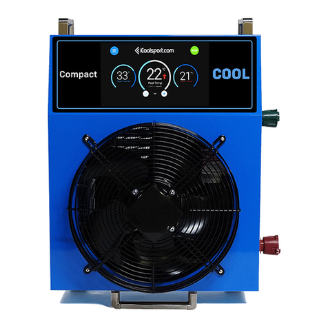
iCoolsport 5 Series User manual

Series 5
Owner’s Manual
Turbo Range
www.icoolsport.com | support@icoolsport.com


O1 Your Turbo
O2 Installation Set Up
O3 Get Started
O4 Safety Procedures
O5 Technical Support
Table of contents

Your
Turbo
O1

Cooling or Heating
The Turbo Range is the only product available designed
specifically for efficient automatic chilling or heating of
large ice baths. Depending on the model chosen, the
Turbos can cool or heat up to 10,000 L of water across the
entire range used in modern recovery pools from 5ºC to
45ºC (heating available only in Hot or Dual Temp models).
Twin Engine Design
Each Turbo unit is a revolutionary & unique twin engine
design, actually 2 completely separate heat pump systems
built inside a single cabinet. It is very reliable & can continue
to operate even if one side is out of service for any reason.
The biggest advantage of the twin engine design is that it
saves a lot of electricity compared to ordinary chillers.
Smart Control & ONE TOUCH
All models feature an attractive 15 inch Full HD Touch
Screen with the latest advancements in automation that
can be mounted anywhere you need. The modern user
interface has been completely redesigned to provide
fully automatic start up and operation and displays all
temperatures plus lots of useful information. Just set the
temp, touch START, and that’s it!
The Turbo machine is designed to provide both cooling and heating for large recovery pools & spa baths.
It is now the most popular machine in the world for this purpose. A large number are already operating
successfully in stadiums, colleges & sporting clubs in many countries, becoming the world standard
for commercial ice baths. They can produce an extremely impressive chilling & heating performance of
moving either 15,000 or 20,000 watts of heat per hour (depending on the model) from a compact easy to
install package that takes up much less space & weights a lot less than any comparable machine.
What’s new in Series 5
Premium Quality
All metal work is manufactured in Australia from marine
grade aluminum with a double layer of epoxy paint coating
for long life durability. The 2 heat exchanger tanks are
made from the highest quality Titanium tubing, which
means they can withstand all normal pool chemicals and
even salt water. However, we recommend against using
highly corrosive bromide based chemicals.
The two powerful rotary compressors in each machine are
manufactured by the highly respected Mitsubishi company.
Cooling air fans are manufactured in Europe and designed
for long service life and low noises. Electronic components
and systems software are designed and manufactured in
Australia.
24/7 Operation
The Turbo is built to be always on and always ready every
day of the year in any home or commercial applications.
It can operate for a single session or around the clock for
years on end automatically. The sophisticated on board
computer will manage the electrical power usage to the
absolute minimum needed to maintain your desired
temperature while providing large savings in running costs
compared to ordinary chillers.

6
Identify your model
Your device’s model name is printed on your order/invoice.
> TurboCool (Chill only)
> TurboHot (Hot only)
> Turbo Dual Temp Hot or Cold)
Identify your serial number
Your Device ID (or Serial Number) is noted on the label
attached at the back of your product.
Identify your series
The Series of your product corresponds to a certain ‘batch’
of units made at a certain time. The Series is marked on the
Serial Number label & on the front page of your owner’s
manual.
This manual is intended to help you get started using the Turbo Range of cooling units. To know your
device’s features, specifications and operation instructions, you will first need to identify your product.
Below are some guidelines to help you determine your model, your series and your serial number.
Identify your Turbo
Remote 15inch Full HD Capacitive Touch Screen
Wall-mount bracket & screws kit
Front View Back View Side View
DATA cable 20 meters
Owner’s Manual
2x PVC Barrel Unions for 40mm pipes
Serial
Number Label
Included with your Turbo
Industrial Water Pump
iCool-
sport
Turbo
Series3

7
Cabinet is constructed from high
quality marine grade aluminium to
prevent rust and save weight. All
metal parts are coated with high
grade heat cured epoxy paint to
resist extreme conditions.
Extra strong mounting bars with slots to
fit standard floor, wall or ceiling mounting
hardware.
Built in strong lifting handles for ease
of placement.
All electronics and electrical
components are protected in a
sealed separate metal box and easily
accessed behind this smoked glass
cover.
Mounting Bars
Cabinet
Lifting Handles
Sealed
Electrical Box
Control Touch
Screen
A large Hi Definition 15”
colour touch screen with
wall mounting provisions
controls all functions and
settings and provides
complete information
on temperatures,
modes of operation and
diagnostics. The screen
controls automatic
chilling or heating and the
management of connected
ice baths.
Industry standard 40mm PVC pressure pipe
quick connection port to collect water from the
pool for chilling or heating.
Weather proof power connection box. Requires
only low cost single phase power.
Industry standard 40mm PVC pressure pipe quick
connection port to return chilled or heated water to
the pool.
Water Inlet Port
Power Connection Box
Water Outlet Port

8
Specifications
Cabinet and Chassis Marine Grade Aluminium (to prevent rust and save weight)
Coatings Heat Fused Appliance Grade Enamel (to resist extreme conditions)
Heat Exchanger Titanium (To resist common pool chemicals and salts)
Heat Pump Plumbing Commercial Refrigeration Grade Copper
1050.0 mm 41.3 in/
850.0 mm 33.5 in/
348.0 mm 13.7 in/
TurboCool 2 & TurboCool 2 XP Dimensions
520.0 mm 20.5 in/
18 ° 1050.0 mm 41.3 in/
348.0 mm 13.7 in/
241.00 mm 9.49 in/
R
RI
IG
GH
HT
TF
FR
RO
ON
NT
TL
LE
EF
FT
TB
BA
AC
CK
K
Ø 54 OUT
Ø 54 WATER IN
ELECTRIC POWER IN
370 mm
COLD HOT
Dimensions
Materials
iCool Systems are sold all around the world and these specifications may be different for units
delivered in your country due to local conditions or regulations or other factors. Also certain
specifications may change due to ongoing research and development, because we are constantly
improving our products. We welcome your feedback and suggestions and we offer support for general
inquiries and information for specific countries on our website at www.icoolsport.com

9
Cooling Power 15,400 Watts 15,400 Watts 8,900 Watts 20,000 Watts
Heating Power Chill Only 15,200 Watts Chill Only Chill Only
Run (& Max.) Power
208-220 Volts
14.8 Amps (20 Amps)
Single Phase
14.8 Amps (20 Amps)
Single Phase
9 Amps (15 Amps)
Single Phase
17.1 Amps (20 Amps)
Single Phase
Heat Pump Type Rotary Compressors x2 Rotary Compressors x2 Rotary Compressor x2 Rotary Compressors x2
Earth Leak Safety
Device Yes 30 Milliamps Yes 30 Milliamps Yes 30 Milliamps Yes 30 Milliamps
Titanium Heat
Exchanger Tank 2 x 25 Litres 2 x 25 Litres 1 x 30 Litres 2 x 25 Litres
Power Management
System Intelligent Digital Intelligent Digital Intelligent Digital Intelligent Digital
Standard Mounting
Available Mounting
Options
Anti Vibration Feet
or Wall Mounting
Anti Vibration Feet
or Wall Mounting
Anti Vibration Feet or
Wall Mounting
Anti Vibration Feet
or Wall Mounting
Air Flow 4,000 Cubic Ft/
Minute
4,000 Cubic Ft/
Minute
4,000 Cubic Ft/
Minute
4,000 Cubic Ft/
Minute
HD Resolution LCD
Colour Touch Screen
15 Inch High
Definition
15 Inch High
Definition
15 Inch High
Definition
15 Inch High
Definition
Maximum Pump
Capacity Up to 550 watts Up to 550 watts Up to 550 watts Up to 550 watts
Electricity
Connection
Weatherproof
Junction Box
Weatherproof
Junction Box
Weatherproof
Junction Box
Weatherproof
Junction Box
Weight
Kilos / Pounds 96kg 205 Lbs 96kg 205 Lbs 65kg 142 Lbs 96kg 205 Lbs
Dimensions H. W. D.
Centimetres 1050x850x348 1050x850x348 1050x850x348 1050x850x348
Specifications
TurboCool Turbo Dual Temp Turbo Hot Turbo XP

Quick
Set up
O2

Unboxing
We strongly recommend keeping the original packaging of
your unit for as long as your warranty lasts. It can be used if you
ever re-locate the machine and offers you peace of mind for
transport.
Turbo and Team Recovery (TR) Pools are delivered in wooden
transport crates or pallets. The timber we use is approved for
export. Generally a forklift will be required to move and place
the pools. iCool can provide as much technical support as you
need to place and connect your set up.
To unpack your Turbo, unscrew the bolts from the wooden
crate starting from the top panel, then the sides. First thing to
note is to make sure nothing is missing.
Mounting Options
For mounting on a concrete floor it is OK to use the smaller
feet that are supplied as standard with the Turbo. However, we
recommend that you replace these feet with the larger vibration
isolating feet if mounting on a wooden floor or on wall or
ceiling brackets. The Turbo is provided with special slots in the
strengthening beams on the bottom of the unit in to which the
attachment bolt of these special rubber feet can be secured. If
using the special feet then the small feet should be removed.
Maximum lift for the standard pump is 3 meters, however, plus
or minus 5 meters or more can be achieved with an optional
pump.
Prepare for set up
Outdoor Operation
The best location for maximum performance is outside the building
in an area with good fresh ventilation. The Turbo should be protected
from direct rain, hail, snow and sun. Never install a Turbo in direct
sunlight which can add a large amount of heat to the system and
reduce performance and increase the running cost. It only requires
reasonable over head cover such as a veranda or an awning to
prevent this. A small roof about double the size of the Turbo but with
no walls works very well too. The Turbo is made from marine grade
aluminium so it will generally last much longer than ordinary steel
cabinets, however, direct sunlight can damage the paint finish over
time.
Your TR pool must be placed on a uniformly flat and level surface.
Be sure to place the pool on an area that can support the weight of
the bath when full (water is very heavy, 1KG per Liter). It is always
recommended that you seek the advice of a qualified engineer or
the local council if unsure. If eventual servicing is required for any
particular reasons, please also make sure that you have easy access
to all accessories. We suggest that you closely consider the required
location for your ice bath and that you account for drainage of your
pool and attachment point to drain the surplus water, prior to filling
your bath.
Indoor Operation
When operating Turbo indoors then the air flow in the room must be
enough to carry away up to 15,000 watts of heat. Otherwise it will
reach unsafe temperatures that will cause the inbuilt safety system
to operate and shut down the unit. The airflow must be equivalent to
at least 4000 cubic feet per minute through the enclosed area.
Extreme Weather Exposure
If using your machine in extreme cold temperatures, never allow the
water to freeze or serious damage could occur that is not covered
under warranty. If freezing conditions are expected, empty the water,
add anti-freeze to the water or turn on the heating mode if your
model has that function to keep water above freezing.
On very hot climates over 45ºC, it may not be possible to run the
system at full power due to the excessive heat. If the temperature
inside the unit exceeds 70ºC, the over heat safety circuit will operate
and shut the machine down.
To make setup as smooth as possible, please follow
carefully the instructions outlined below. Do not start
your Turbo until you have read this entire owner’s
manual. Improper installation or operation may result
in equipment damage not covered by warranty.

12
A drip tray is recommended to catch
condensation. Condensation occurs mostly
in the heating mode (more than in cooling
mode). The amount depends on the humidity
in the air.
Drip Tray
Other key points
Water Condensation
Please note that your unit is a very powerful chiller and
condensation will occur inside of your machine and you may
notice a small amount of water at the base. Condensation is
water from the air being condensed as ice or water on the very
cold surfaces of the iCool’s machinery. This is more evident in
high humidity where the air contains a lot of water.
Access Limitations
Please observe the overall dimensions shown elsewhere in
this document to ensure that the pools can fit through the
building’s openings.
Note that some pipes and fittings may protrude slightly
outside the dimensions of the stainless steel frames. This must
be considered when calculation access.
It may be permissible to remove some pipes and replace
them after gaining access. Please ask our advice and always
thoroughly check any pipework refitted for any leaks.
Please read this manual in full before starting or commencing installation. iCool can provide as
much technical support as you need to place and connect your set up. Simply contact us for more
information or for any specific request regarding your set up.

13
Overhead protection from
direct sun and heavy rain
is essential.
Min 300mm For Plumbing and ventilation.
Good Airflow
Please ensure your Turbo is placed at a minimum distance of
300mm on all sides away from any obstacle, wall or structure to
allow proper airflow. Please also make sure it is kept away from
heat sources of any description. You must provide appropriate
ventilation to keep the machine within a safe operating
temperature.
The Turbo is a very powerful heat pump and when removing
heat from the water in a large pool it must exhaust up to
15,000 watts of heat in to the surrounding air. Even cold
water still produces a lot of heat. The Turbo can not perform
correctly if the large fan can not move all the heat away. As
the air temperature inside the Turbo increases the cooling
performance will be reduced, this is normal for all heat pumps
& refrigerator machines. The inbuilt power management
system in the Turbo will need to increase the use of electricity
to overcome a higher than normal heat load. Therefore, good
ventilation is essential and will save you a lot of money over
time by greatly reducing running costs.
Please note 300mm is the minimum front and back distance
from walls or large objetcs, but more is better. If there is a large
obstacle or wall too close it can cause this powerful machine’s
waste heat to be sucked back in to the machine which will
reduce the performance and may cause over heating.
Water Leak Testing is Essential
As your pool has been transported over distance it is
essential that you check to make sure none of the many
plumbing fittings has been moved or loosened during road
transportation or general handling.
When the pool is in place and connected to the Turbo you
MUST fill it with water to perform a leak test. Generally it will
be very difficult to reach most fittings once the room finishes
and cladding are added to the sides of the pool. If necessary
tighten any fitting that shows any sign of leakage.
More is better if possible to prvent the hot
air from the rear being reflected back into
the powerful front fan

14
Turbos can be mounted anywhere within 70 meters of your pool and can be either level with the pool
or up to 12 meters above or below the pool using an option high lift pump (separate special order).
Installation must be completed by a certified plumber, builder or installer and they must follow iCool’s
guidelines and instructions. Improper installation or operation may result in equipment damage not
covered by warranty.
Basic Connections
Water Pipes (not supplied)
Only 2 pipes are required as shown in the diagram. These pipes
are not factory installed to prevent damage during transport.
Both pipes should be 50mm pool grade PVC pressure pipes
(standard product available in most countries). It is essential
that the pipes be well insulated otherwise a great deal of
energy will be lost due to the transport of very cold water.
Pipe Insulation (not supplied)
All water pipes must be entirely insulated with standard tubular
aluminium foil covered foam insulation (90-100mm). This is a
standard product available in most countries.
This insulation prevents the large energy losses that would
occur otherwise due to the big differences between the water
temperature in the pool and the environment. Insulation
dramatically reduces running costs and speeds up cooling and
heating of the pool water.
If ordering an iCool TR Pool with your Turbo, the pool shell is
insulated at the factory before delivery for this purpose.
Water Suction Safety
By law there must be at least 2 suction points that collect the
water from the pool. Usually one of these is the skimmer box
and the second is a suction fitting elsewhere in the pool such
that a person can not reach both of them at the same time.
This is pre-fitted by iCoolport if you have ordered an iCool TR
Pool with your Turbo.
Water Circulation Pump
A Davey QB035 water circulation pump is supplied with
your Turbo. If not using the supplied pump, a water pump
of between 250 & 700 watts is required. Do not use pumps
of higher power or efficiency will be compromised. Also the
maximum allowable pressure in the titanium heat exchangers
could be exceeded. Maximum 5 Bar or 72PS.
Spa Jets Pump (optional)
If you have ordered a TR pool with massage jets with your
Turbo machine, a spa jets pump will be supplied. Please refer
to TR Pool installation manual for more information.
The pumps are normally placed under the pool steps, but can
be placed anywhere that is convenient.
If placed under the pool, access must be provided to reach the
pumps for future maintenance.
Drain Valve (not supplied)
A manual gate valve is connected to the heat pump suction
line to allow the pool water to be drained. The drain valve can
alternatively be connected to the spa jet pump inlet if you are
using a pool with massage jets.
The gate drain valve must be accessible after installation. If
this is not practical, an electric water valve should be installed
instead of the manual valve to allow remote control of the valve
for draining.
(supplied)

15
Pipe Insulation
If no filter, connect
bottom of Turbo to top
of pump directly
OPTIONAL
WATER FILTER
50mm PVC
Pressure Pipes
50mm PVC Pressure Pipes
WATER
CIRCULATION
PUMP
From POOL
to TURBO
From TURBO
to POOL
(supplied)
OPTIONAL JETS
(Optional on TR Pools with spa jets)
(Optional on TR Pools
with spa jets)
Main suction from
skimmer box
Optional items on TR Pools with spa jets
Please refere to TR Pool manual for more information
Water flow direction

16
Turbos require only standard single phase power, one flow and one return water pipe and a data
cable (supplied) to connect to the wall mounted remote control touch screen. The pump must also be
connected to the electronic side of the Turbo and works must be completed by a certified electrician,
builder or installer. Improper installation or operation may result in equipment damage not covered by
warranty.
Power Connection
Power Connection
Electric Power Input Recommendations
A certified electrician should connect the Main Power of your
machine.
For Europe, China, Asia, S.E Asia, Africa, India, The Middle East
and Australia Turbos require only a single phase 208-240 volt
supply @ 50Hz or 60Hz. The maximum load is 20 amps and the
typical operating load varies from 8 to 16 amps. An RCD safety
device is built in to the machine, however it is recommended
that the building fuse also incorporates an RCD Please avoid
the use of long extension cords as they may result in voltage
drops that may trigger the inbuilt safety system.
For the USA, Canada, South America and Japan, voltages from
208 to 240 volts are generally readily available on the local
power grid and can be provided to most buildings, in fact
many houses and buildings in these countries already have
higher voltage between 208 & 240 volts connected for high
current devices such as clothes dryers, etc. Higher voltages are
more efficient and provide better performance for high power
products like Turbo machines.
Turbos must be connected to the voltage marked on the
machine, /!\ they are NOT multi-voltage and using a
different voltage may cause severe damage.
Your Turbo is fitted with an electrical safety device to protect
users and all AC power connections used must have an earth
connection that complies with your local electrical safety
regulations.
Screen Connection
The Remote Control Touch Screen with Wall Mounting Box can
be positioned anywhere within 40 meters of the Turbo. It must
be mounted in a dry place and comes with a multi world voltage
power supply that requires 100-240 volt 10 amp single phase
power supply.
The screen is connected to the Turbo by a single twisted pair
cable (provided). The default factory pre-wired control cable
provided by iCool is 20 meters. If further length is required,
this can be obtained at any local electronics store (twisted pair
cable).
A certified electrician must do the wiring. See wiring
instructions in Pages 18-19.
Pump Connection
The water flow pump i controlled by the TurboCool electronics
for safety. The QB035 Davey Water Circulation Pump must be
wired to the electronic side of your Turbo. A certified electrician
must do the wiring. See wiring instruction in Pages 20-21.
Please note: the pump needs to be the same voltage as the
Turbo unit.

17
DATA CABLE
(20 mtrs supplied)
twisted pair cable
SCREEN POWER CABLE +
MULTI WORLD VOLTAGE BRICK (PROVIDED)
15 INCH
TOUCH SCREEN
CIRCULATION PUMP CABLE
If no filter, connect
bottom of Turbo to top
of pump directly
OPTIONAL
WATER FILTER
50mm PVC
Pressure Pipes
50mm PVC Pressure Pipes
WATER
CIRCULATION
PUMP
From POOL
to TURBO
From TURBO
to POOL
OR
220volt
20 amps
110volt
40 amps

18
DATA CABLE
SOLID BLUE WIRE TO PIN A (RS485)
BLUE/WHITE STRIPE WIRE TO PIN B (RS485)
DATA CABLE WIRING TO CIRCUIT BOARD
The blue Data cable must be wired into the bottom circuit
board located inside the electronic side panel of your turbo.
The blue data cable supplied is 20metres long. If you need
a longer distance, please make sure to use STP or UTP cable
for reliable connection. Electric power cable or regular multi
core cable cannot handle high frequency data.
The Data cable needs to be a twisted pair type.
Both wires must be connected to the bottom large green
8-pin connector as shown.
1The solid blue wire must be connected to the Pin A in
RS485
2The blue and white stripe wire must be connected to the
Pin B in RS485
Screen Connection
Turbos come with a 20m data cable. For longer distance, please use STP or UTP cable for reliable
connection.

19
DB9 Female connector (supplied)
If using a longer cable, make sure to
use a DB9 Female connector wired
up for RS485. The pinout is listed
below. Ensure twisted pair cable is
used for long distances.
DB9 Male connector (included in screen)
Connect blue data cable here
12 volt DC Power cable to the screen
from the multi voltage power brick
provided
DATA CABLE WIRING TO SCREEN
The blue Data cable must be connected to the DATA - DB9 Male Connector on the screen.
The screen must also be connected to the power via the DC power cable supplied.
RS485RS232

20
To Water Circulation Pump
PUMP WIRING TO CIRCUIT BOARD
The water circulation pump must be wired
into the top circuit board located inside the
electronic side panel of your turbo.
208-240V supply will output from the board to
the pump. The cable supplied is 5 meters long.
Directly powering the circulation pump from
this PCB is acceptable for cable runs of up to 15
meters & for pumps up to 750 watts.
If the distance is longer or the pump used is
larger, we recommend powering the pump from
a closer 220 volt power source that is switched
by the output of this line through a slaved relay
with a 220 volt coil.
Pump Connection
Wires must be connected to
the bottom large Grey 6-pin
connector as shown in the
PUMP section.
NOTE: Pumps of more than
1000 watts may exceed the
Turbo’s exchanger tanks
pressure limits.
Turbos come with a QB035 Davey water circulation pump that must be wired to the circuit board.
Other manuals for 5 Series
1
Other iCoolsport Range manuals
Popular Range manuals by other brands

Bertazzoni
Bertazzoni PRO365GASX Installation, use & care manual

GE
GE JBP90 owner's manual

Frigidaire
Frigidaire FFGS3025LBB installation instructions

Fisher & Paykel
Fisher & Paykel OR24SDPWSX user guide

Jenn-Air
Jenn-Air JDS9860CDW01 installation instructions

Frigidaire
Frigidaire CGLGF386GSD Use & care manual