ICOP Technology ICOP-6036E User manual

ICOP-6036VE/6036E
Embedded 5x86 3.5"-size All-in-One CPU
Board Series
User’s Manual
(Version 3.3)

ii
Copyright Notice
This document is copyrighted, 2000 by ICOP Technology Inc.
All rights are reserved. The information in the manual is
subject to change without notice in order to improving products.
No part of this manual may be reproduced, copied, translated
or transmitted in any form or by any means without the prior
written permission of the manufacturer.
ICOP Technology Inc. assumes no responsibility for any
inaccuracies that may be contained in this document. ICOP
Technology Inc. makes no commitment to update or to keep
current the information contained in this manual.
Copyright 2000 by ICOP Technology Inc.
All rights reserved. Ver.2.1 2000,
Printed in Taiwan
Trademarks Acknowledgments
All brand names and trademarks are the properties and
registered brands of their respective owners.

iii
T a b l e o f C o n t e n t s
C h a p t e r 0 Startup
0.1 Packing List .............................................................. 1
0.2 Specifications ........................................................... 2
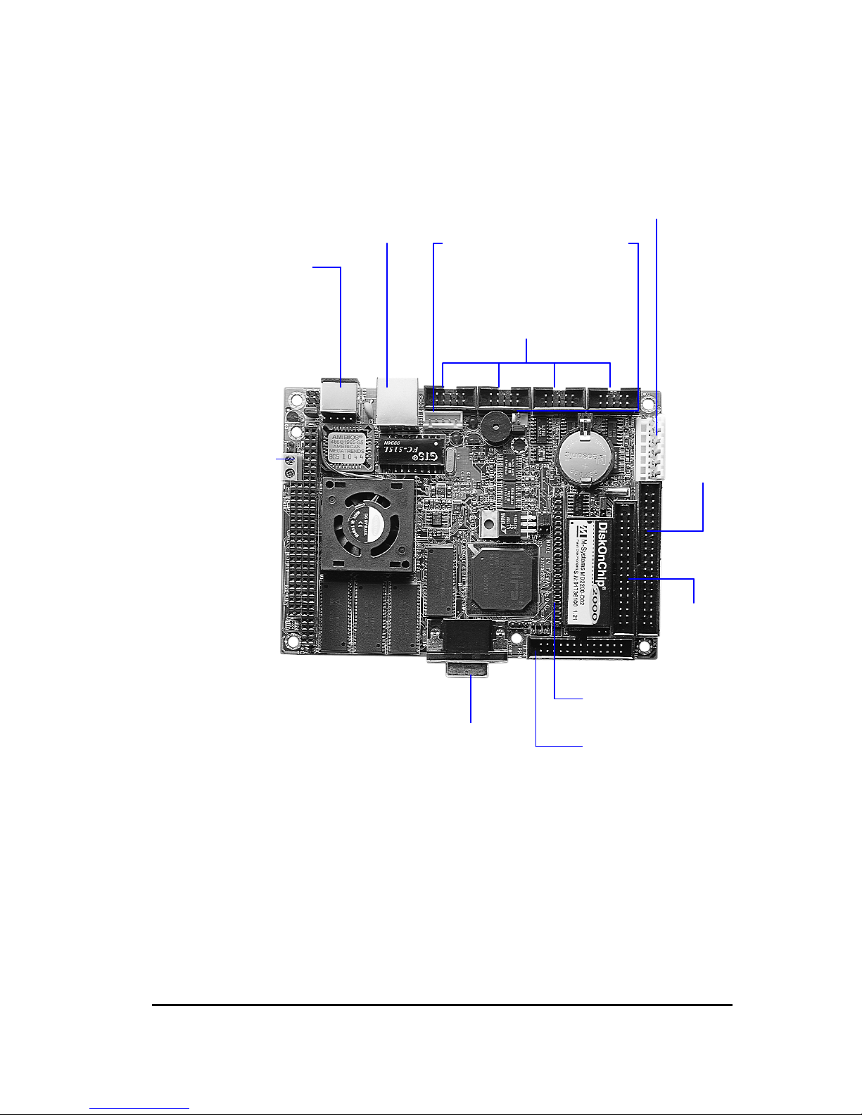
0.3 Component Location ................................................. 3
C h a p t e r 1 Introduction
1.1 Features .................................................................... 4
1.2 Specifications ........................................................... 5
1.3 VGA Interface ............................................................ 7
1.4 DiskOnChip 2000 Flash Disk..................................... 9
1.5 Network Interface .....................................................10
C h a p t e r 2 Installation
2.1 Jumper Settings .......................................................11
2.1.1 ICOP-6036VE ............................................................. 12
2.1.2 ICOP-6036E ............................................................... 13
2.2 Connectors ...............................................................15
2.2.1 ICOP-6036VE ............................................................. 15
2.2.2 ICOP-6036E ............................................................... 15
2.3 DiskOnChip/Flash ROM Disk....................................17
2.3.1 Setup a DiskOnChip ®2000 Flash Disk ..................... 17
2.3.2 Setting up a Flash Disk.............................................. 18
2.4 Watchdog Timer .......................................................19
2.5 General Purpose I/O .................................................23
C h a p t e r 3 SVGA Setup
3.1 Introduction..............................................................25
3.1.1 Chipset ...................................................................... 25
3.1.2 Display memory ........................................................ 25
3.2 Installation of SVGA driver ......................................25
3.2.1 Installation for Windows 3.1 ..................................... 27
3.2.2 Installation for Windows 95/98 ................................. 29
C h a p t e r 4 Network Interface

iv
4.1 Introduction..............................................................31
4.2 Software Support .....................................................32
Appendix Pin Assignments
IDE Interface Connector................................................... 34
VGA/Flat Panel Connectors ............................................. 35
Floppy Disk Connector...................................................... 37
Parallel Port Interface ....................................................... 38
Serial Port Interface........................................................... 39
Keyboard and PS/2 Mouse Connector ............................ 40
PC/104 Connectors ........................................................... 41
Warranty

ICOP Embedded 5x86 3.5"-size AIO CPU Board User's Manual 1
C h a p t e r 0
Startup
0.1 Packing List
Product Name Function Package
ICOP-6036E
Embedded 5x86
3.5"-size All-in-
One CPU Board
ICOP-6036E Embedded 5x86 3.5"-size
All-in-One CPU Board
Utility and Drivers Diskette x 2
FDD cable x 1
HDD cable x 1
RS232 cable x 4
Printer cable with bracket x 1
AT KB / PS2 Mouse Y-cable x 1
ICOP-6036VE
Embedded 5x86
3.5"-size All-in-
One CPU Board
with VGA/LCD
ICOP-6036VE Embedded 5x86 3.5"-
size All-in-One CPU Board
Utility and Drivers Diskette x 2
FDD cable x 1
HDD cable x 1
RS232 cable x 4
Printer cable with bracket x 1
AT KB / PS2 Mouse Y-cable x 1
VGA cable x 1

2 ICOP Embedded 5x86 3.5"-size AIO CPU Board User's Manual
0.2 Specifications
Features ICOP-6036E ICOP-6036VE
Chipset SGS STPC Client, 66/75 MHz
Processor 5x86 CPU on-die
Multi I/O Chip Winbond W83977F-A, ALi 5113
BIOS AMI BIOS
Watchdog Timer From 1 to 64 seconds
Bus Interface PC/104 standard compliant
Memory 8MB onboard, up to 16MB onboard
Memory Sockets 1
DiskOnChip Socket 1
VGA Chipset STPC Client C&T 69000 (2MB)
Display CRT VGA/LCD
Enhanced IDE Port 1
Floppy Connector 1
Network Chipset Realtek 8139AS
Network Interface RJ-45
Serial Port RS232 X 4 (or RS232 X 3,RS485 X 1)
Parallel Port 1
Power Requirement +5V @1.6A
Board Weight 300g
Board Size 102mm X 144 mm
Operating Temperature -20 ~ +60°C

ICOP Embedded 5x86 3.5"-size AIO CPU Board User's Manual 3
0.3 Component Location
ICOP-6036/6036VE
PS/2
Keyb.
Ethernet
RJ-45
COM4/3/2/1
RS-485
+5V
GND
P8 Power Cont.
EIDE
Port
FDD
Port
Flat Panel
CRT
SVGA
Parallel Port
Keyb.
Cont.

4 ICOP Embedded 5x86 3.5"-size AIO CPU Board User's Manual
C h a p t e r 1
Introduction
1.1 Features
3.5’’-size (144x102 mm) Embedded CPU Module
PC/104 connector
SGS STPC Client 5x86 processor with FPU unit
CRT and Flat Panel Display interface
8MB EDO RAM onboard and up to 16MB by expansion
Enhanced IDE devices and FDD interface
One Bi-directional Parallel Port
RS-232/485 interface
Watchdog timer
Socket for Flash or DiskOnChip
Onboard Keyboard, Mouse connector
Onboard Ethernet, compatible with NE2000
Single voltage +5 V power connector
Operating temperature from –20 •+60•
Flexible OEM/ODM design

ICOP Embedded 5x86 3.5"-size AIO CPU Board User's Manual 5
1.2 Specifications
Chipset: SGS ST PC Client, 66/75MHz, 64-bit internal architecture
x86 processor with FPU unit
Enhanced IDE, Scatter/gather and Multi-word DMA
Data Bus: 16-bit
Bus Speeds: ISA - 8.3 MHz, PC/104 - 8.3 MHz
DMA Channels: 7
Interrupt Levels: 15
Watchdog Timer: from 0.5 to 32 seconds
Real-Time clock
BIOS: AMI BIOS
RAM: 8 MB up to 16 MB of EDO DRAM
I/O: Winbond W83977F-A, ALi 5113
two floppy drives
two hard drives or Enhanced IDE devices
three RS-232 port, one RS-232/485 port
Bi-directional Parallel Port
Bus Interface: PC/104
Connector:
External 9-pin D-Type male RS232 connector
External 15-pin D-Type female VGA connector
External 6-pin Mini DIN for AT-keyboard, PS2 Mouse
10-pin box header for RS232 port X 4
25-pin box header for parallel port
5-pin header for AT-keyboard
50-pin box header for flat panel VGA
2-pin header for RS485 port

6 ICOP Embedded 5x86 3.5"-size AIO CPU Board User's Manual
34-pin box header for floppy disk drive
40-pin box header for enhanced IDE
6-pin P8 power connector
One socket for flash ROM or DiskOnChip
RJ-45 connector for 10/100BASE-T
Display:
(ICOP-6036VE)
• Chipset: C&T CHIPS 69000
• Memory: 2MB integrated memory
• Display: resolution up to 1024x768 @ high colors
• Compatibility: VGA, TFT, DSTN, SSTN, EL, Plasma hardware
• OS Support: DOS, Windows, Windows 95/98, Windows NT, Windows CE,
QNX, OS/2
(ICOP-6036E)
• Chipset: built-in ST PC Client
• Memory: 256 KB ~ 1 MB shared with system memory
• Display: CRT resolution up to 1024x768
• Compatibility: VGA hardware
• OS Support: DOS, Windows, Windows 95, Windows NT, Windows CE,
QNX, OS/2
LAN: Realtek 8139BL single chip
NE2000 compatible with built in 16 KB RAM buffer
Throughput : 10/100 Mbps
Power Requirements: single voltage +5 V @ 1.6 A
Dimensions: 102 (L) x 144 (W) mm.
Weight: 300g
Operating Temperature: -20~+60 °C

ICOP Embedded 5x86 3.5"-size AIO CPU Board User's Manual 7
1.3 VGA Interface
(ICOP-6036E)
The STPC integrates a full VGA Controller with Extended Functions together
with an output Color Digital to Analog (RAMDAC) and a Graphics Engine.
The VGA Controller provides the basic video display function. It generates
the timing and logic required to create an output data streamfrom the video
buffer and the appropriate horizontal and vertical synchronisation pulses.
The Frame video buffer exists in the main DRAM memory in the first 1M of
the memory space. This Frame buffer area is selected upon configuration of
the VGA video output and, once selected thefunction of the Frame buffer
area can not be changed back to normal DRAM memory program/data
functions until the next reset cycle.
Resolutions of up to 1024x768 and color depths of 8, 16, 24 and 32 bits per
pixel are supported. The integrated RAMDAC supports digital to analog
conversion rates of up to 135 MHz. This along with the peak video
bandwidth of 320 MBytes/sec (using EDO DRAMs) enable the VGA
Controller to support 1024x768x24 and 800x600x32 resolutions at 75 Hz
refresh rate. To support vertical resolutions up to 1024 pixels, vertical timing
parameters have been extended from 10 to 11 bits. The VGA defined
horizontal timing parameters are compatible with the above resolutions. The
horizontal and vertical timing counters and the sync and blank generation
logic operate synchronously to DCLK which can be up to 135MHz in
frequency.
The on-chip triple RAMDAC runs at up to 135MHz, using and external
frequency synthesizer, allowing a display up to 1024x768 at 75Hz. Color is
handled using 8-, 16-, 24- or 32-bits per pixel. VDU Graphics standards can
be read through the on-chip Display Data Channel (DDC) link.
The Graphics Engine provides a high performance 64-bit windows accelera-
tor. It is completely backward compatible with the VGA and SVGA standards.
Hardware acceleration is provided for BITBLTs, transparent BLTs and fills
and text (generalised bit map expansion).
The Graphics Core is capable of using up to 1MB of available
memory as its frame buffer. The Cathode Ray Tube Controller (CRTC)
Start Address uses 20-bits to allow locating the frame buffer at any
double word boundary within this 4Mb of memory.
(ICOP-6036VE)
The 69000 accelerator extends CHIPS's HiQVideo™ Series of mobile
graphics/video accelerated controllers by embedding 2 MBytes of

8 ICOP Embedded 5x86 3.5"-size AIO CPU Board User's Manual
high speed SDRAM into the chip.
The 69000 is the first member of the HiQVideo family to integrate
high speed SDRAM frame buffer memory into the chip. Using leading
edge embedded memory logic technologies, the 69000 integrates 2
MBytes of SDRAM into the chip. By embedding SDRAM and graphics
controller logic on the same die, the 69000 delivers uncompromised
performance and at the same time consumes much less power than
the discrete solution. The integrated SDRAM supports up to 83MHz
operation, which provides up to 664MBytes/second frame buffer
bandwidth. The increase in the frame buffer bandwidth enables the
69000 to support high color, high-resolution graphics modes and real-
time video acceleration.
The 69000 is a highly integrated graphics/flat panel controller for
notebooks, mini-notebook, industrial PC, and palmtop applications.
By integrating 2MByte of SDRAM, graphics, flat panel, and CRT
control logic on the same die, 69000 delivers superb 2D video
performance, consumes minimal power and at the same time reduces
the PCB real estate for the graphics subsystem. The 2MByte
embedded SDRAM is arranged in a 64-bit configuration. The 69000
supports both Frame AGP and PCI bus which enables a wide range
of system platforms.

ICOP Embedded 5x86 3.5"-size AIO CPU Board User's Manual 9
1.4 DiskOnChip 2000 Flash Disk
Flash Disk DiskOnChip ® 2000
• Package: Single Chip FlashDisk in 32-pin DIP JEDEC
• Capacity: 1-144 MByte capacity
• Data Reliability: ECC/EDC error correction
• Memory Window: 8 Kbyte

10 ICOP Embedded 5x86 3.5"-size AIO CPU Board User's Manual
1.5 Network Interface
• Chipset: Realtek 8139BL single chip
• Type: 10/100BASE-T
• Connectors: onboard RJ-45 connectors
• Monitoring LEDs: network ready indicator, network activity indicator
• Compatibility: NE2000

ICOP Embedded 5x86 3.5"-size AIO CPU Board User's Manual 11
C h a p t e r 2
Installation
2.1 Jumper Settings
ICOP-6036/6036VE
KB1
J1
RJ45
CONT9/8/6/COM1
CONT5
J6
CONT10
CONT4
IDE1
J5
CONT7
CONT1
P1
J2
J3
JP1
JP3
JP2
JP7/JP6
JP8

12 ICOP Embedded 5x86 3.5"-size AIO CPU Board User's Manual
2.1.1 ICOP-6036VE
JP1 CPU Clock
Speed 1-2 3-4 5-6 7-8
75 open open open close
66 open close close close
60 open close open close
50 open close close close
25 close open open close
JP2 IDE LED
JP3 RS-232/485 selection
1-2: RS-232
2-3: RS485
JP6 DOC address select
DOC address 1-2 3-4 5-6
C800H (default) close close close
CA00H close close open
CC00H close open close
CE00H close open open
D800H open close close
DA00H open close open
DC00H open open close
DE00H open open open
JP7 LCD connector power select
1-2: +5V, +12V
2-3: 3.3V
JP8 COM3/COM4 IRQ# Selection
COM3: 1-2 : IRQ4 2-3 : IRQ10

ICOP Embedded 5x86 3.5"-size AIO CPU Board User's Manual 13
COM4: 4-5 : IRQ3 5-6 : IRQ11
J3 RESET Switch
J6 PS/2 mouse IRQ12 select
close: Enabled
open: Disabled
2.1.2 ICOP-6036E
JP1 CPU Clock
Speed 1-2 3-4 5-6 7-8
75 open open open close
66 open close close close
60 open close open close
50 open close close close
25 close open open close
JP2 IDE LED
JP3 RS-232/485 selection
1-2: RS-232
2-3: RS485
JP6 DOC address select
DOC address 1-2 3-4 5-6
C800H (default) close close close
CA00H close close open
CC00H close open close
CE00H close open open
D800H open close close
DA00H open close open
DC00H open open close
DE00H open open open
JP8 COM3/COM4 IRQ# Selection
COM3: 1-2 : IRQ4 2-3 : IRQ10
COM4: 4-5 : IRQ3 5-6 : IRQ11

14 ICOP Embedded 5x86 3.5"-size AIO CPU Board User's Manual
J3 RESET Switch
J6 PS/2 mouse IRQ12 select
close: Enabled
open: Disabled

ICOP Embedded 5x86 3.5"-size AIO CPU Board User's Manual 15
2.2 Connectors
2.2.1 ICOP-6036VE
CONT1 External D-type CRT VGA Display connector
CONT2 40-pin PC/104 bus
CONT3 64-pin PC/104 bus
CONT4 P8 Power connector
CONT5 2-pin COM2 RS-485 MOLEX connector
CONT6 10-pin box header connector for COM2 RS-232
CONT7 Internal 50-pin Flat Panel Display connector
CONT8 10-pin box header connector for COM3 RS-232
CONT9 10-pin box header connector for COM4 RS-232
CONT10
+5V Power connector
J1 5-pin PS/2 connector
J2 5-pin Keyboard connector
J5 FDD connector
IDE1 IDE connector
KB1 External PS/2 and AT keyboard connector
COM1 10-pin box header connector for COM1 RS-232
P1 Printer Port
RJ45 LAN RJ45 connector
2.2.2 ICOP-6036E
CONT1 External D-type CRT VGA Display connector
CONT2 40-pin PC/104 bus
CONT3 64-pin PC/104 bus
CONT4 P8 Power connector
CONT5 2-pin COM2 RS-485 MOLEX connector
CONT6 10-pin box header connector for COM2 RS-232

16 ICOP Embedded 5x86 3.5"-size AIO CPU Board User's Manual
CONT8 10-pin box header connector for COM3 RS-232
CONT9 10-pin box header connector for COM4 RS-232
CONT10
+5V Power connector
J1 5-pin PS/2 connector
J2 5-pin Keyboard connector
J5 FDD connector
IDE1 IDE connector
KB1 External PS/2 and AT keyboard connector
COM1 10-pin box header connector for COM1 RS-232
P1 Printer Port
RJ45 LAN RJ45 connector
This manual suits for next models
1
Table of contents
Other ICOP Technology Motherboard manuals

ICOP Technology
ICOP Technology ICOP-6023VE User manual

ICOP Technology
ICOP Technology VDX-6324RD User manual

ICOP Technology
ICOP Technology VDX2-6554 User manual

ICOP Technology
ICOP Technology VDX2-6524 User manual

ICOP Technology
ICOP Technology VSX-6127 User manual

ICOP Technology
ICOP Technology VEX-6225 User manual