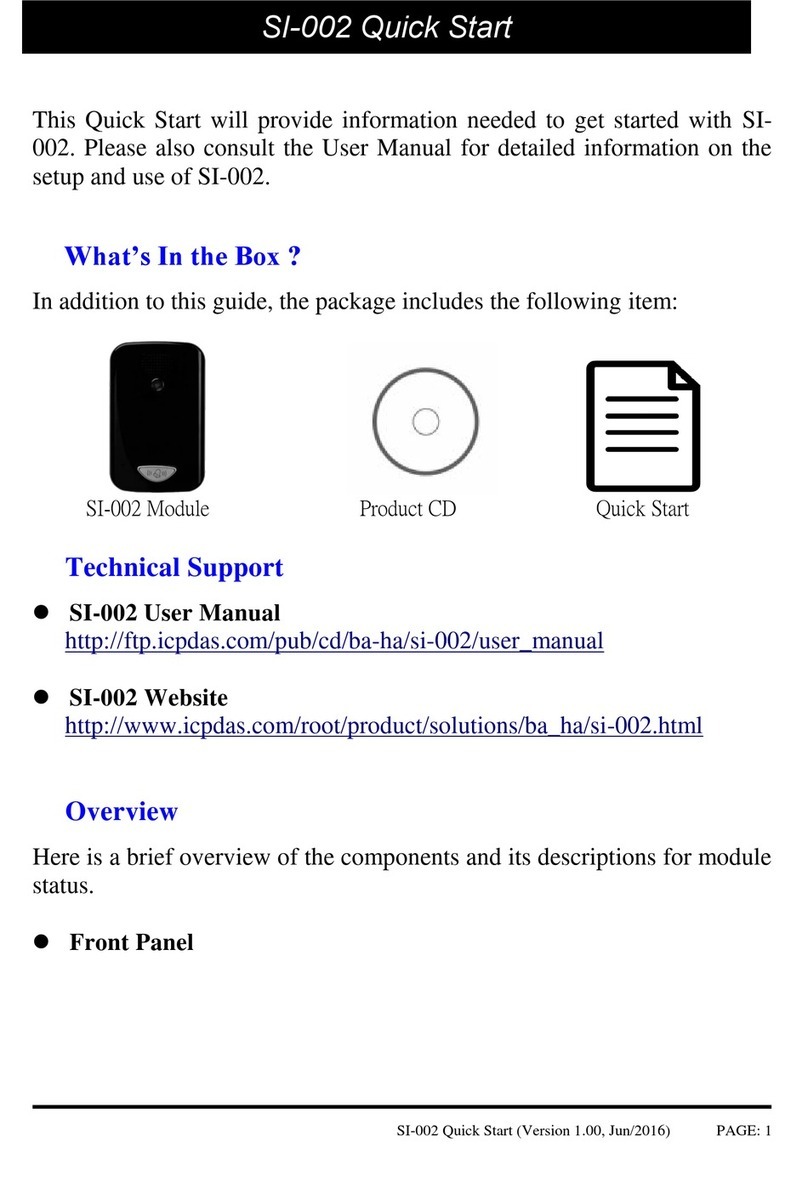
ICP DAS USA SI-002 User manual

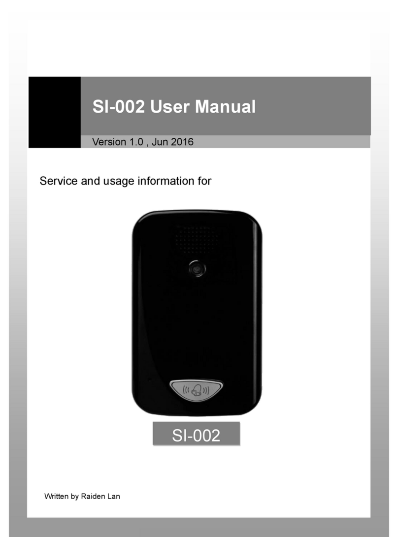
Service and usage information for
SI-002 User Manual
Version 1.1 , Jul 2018
SI-002

SI-002 User Manual, version 1.1 Page: 2
Warranty
All products manufactured by ICP DAS are under warranty regarding defective materials for a
period of one year, beginning from the date of delivery to the original purchaser.
Warning
ICP DAS assumes no liability for any damage resulting from the use of this product. ICP DAS
reserves the right to change this manual at any time without notice. The information furnished by
ICP DAS is believed to be accurate and reliable. However, no responsibility is assumed by ICP DAS
for its use, not for any infringements of patents or other rights of third parties resulting from its
use.
Copyright
Copyright @ 2018 by ICP DAS Co., Ltd. All rights are reserved.
Trademark
The names used for identification only may be registered trademarks of their respective companies.
Contact US
If you have any problem, please feel free to contact us.
You can count on us for quick response.
Email: [email protected]om
Author: Raiden Lan
Editor: Janice Hong

SI-002 User Manual, version 1.1 Page: 3
Table of Contents
Table of Contents ..................................................................................................... 3
1. Introduction......................................................................................................... 5
1.1. Features..................................................................................................................6
1.2. Specification...........................................................................................................6
1.3. DIO Wiring Connection..........................................................................................8
1.4. Overview ................................................................................................................9
1.4.1. Front Panel ..................................................................................................9
1.4.2. Back Panel................................................................................................. 10
1.5. Dimensions ......................................................................................................... 12
2. Getting Started .................................................................................................. 13
2.1. Connecting to the Network, PC and Power ........................................................ 13
2.2. Installing the MicroSIP Utility ............................................................................. 14
2.3. Using SI-002 connects to MicroSIP Utility........................................................... 15
3. Web Applications............................................................................................... 18
3.1. Connect to the SI-002 web site........................................................................... 18
3.1.1. Installing the eSearch Utility .................................................................... 18
3.1.2. Connecting.................................................................................................20
3.2. Web Configuration.............................................................................................. 22
3.2.1. Function menu ......................................................................................... 22
3.2.2. Login ......................................................................................................... 23
3.2.3. User Account ............................................................................................ 24
3.2.4. Standard Config .........................................................................................25
3.2.5. Audio Config ..............................................................................................26

SI-002 User Manual, version 1.1 Page: 4
3.2.6. RFID Config ................................................................................................26
3.2.7. SIP Config.................................................................................................. 28
3.2.8. FTP Config................................................................................................. 29
3.2.9. Information............................................................................................... 30

SI-002 User Manual, version 1.1 Page: 5
1. Introduction
SI-002 is a video intercom door station that supports VoIP technology, SIP communication protocol
and RFID induction. With the HA-401 product, households can see visitors' image and have a video
conversation with them when the doorbell ringing. After the identity confirmation, they can open
the door remotely. Also, users can upload an image shot via FTP.
Using high-resolution CMOS camera and advanced echo cancellation technology can show a clearer
picture and excellent audio quality and timeliness of transport. It is a compact video intercom
solution for residential building.

SI-002 User Manual, version 1.1 Page: 6
1.1. Features
Full-duplex voice and video intercom
Support for SIP communications architecture
Using high-resolution camera 1080P (1920 x 1080)
Advanced echo cancellation technology
Built-in high sensitivity microphone and speaker
Built-in call button
Built-in Relay output channel that can be used for door control or alarm output.
Built-in Digital input channel that can be used for door magnetic switch detection or an
external emergency button.
Support Card Type: Mifare Classic, Ultralight, DESFire
1.2. Specification
System
CPU
Cortex A8 CPU (720 MHz)
SRAM
512 MB
Flash Memory
512 MB
EEPROM
16 KB
Communication
Ethernet Port
RJ-45 x 1, 10/100 Base-T
(Auto-negotiating, Auto MDI/MDI-X, LED indicators)
Digital Input
Channels
2
Input Type
Dry contact (Source)
Dry Contact Level
Off Voltage Level: Open
On Voltage Level: Close to GND

SI-002 User Manual, version 1.1 Page: 7
Relay Output
Channels
1
Output Type
Form C (N.O./COM./N.C.)
Contact Capacity
0.6A @ 125 VAC; 2A @ 30 VDC
Endurance
Mechanical: 2 x 10⁸ops.
Electrical: 1 x 10⁵ops.
RFID
Frequency
13.56 MHz
Supported Card
Mifare Classic, Ultralight, DESFire
HMI
Camera
1080P (1920 x 1080), CMOS Sensor
Audio
AMP 2.5 W; Digital microphone
Mechanical
Installation
Wall Mounting
(Suitable for the European 86 mm x 86 mm outlet box)
Dimensions
102 mm x 161 mm x 41 mm (W x L x H)
Environment
Operating Temperature
-10 ˚C ~ +60 ˚C
Storage Temperature
-20 ˚C ~ +70 ˚C
Humidity
10 ~ 90 % RH, non-condensing
Power Supply
Input Range
12 VDC ~ 48 VDC
Power Consumption
1.68 W (70 mA @ 24 VDC)
Protection
Reverse Polarity Protection

SI-002 User Manual, version 1.1 Page: 8
1.3. DIO Wiring Connection

SI-002 User Manual, version 1.1 Page: 9
1.4. Overview
Here is a brief overview of the components and its descriptions of module status.
1.4.1. Front Panel
Call Button with LED Indicator
When the module is offline and user push call button, the module will dial to preset sip client.
When the module is online and user push call button, the module will end current call.
LED Indicator is used to display the dialing status as shown below.
LED Action
Current status
High brightness
Online
Low brightness
Offline
Speaker
Call Button
Camera
Microphone

SI-002 User Manual, version 1.1 Page: 10
1.4.2. Back Panel
RSW (Rotary Switch)
RSW Value
Function
A
Set network interface to DHCP mode
B
Set network interface to static IP mode.
IP: 192.168.72.30
Mask: 255.255.0.0
Gateway: 192.168.1.1
E
FW Update Mode
F
Recover system settings
Other
N/A
Ethernet Port
J1 Connector (Pin 1 ~ 8)
RSW

SI-002 User Manual, version 1.1 Page: 11
Ethernet Port
An Ethernet port is an opening on SIP network equipment that
Ethernet cables plug into. Ethernet ports accept cables with
RJ-45 connectors.
J1 Connector
Pin
Name
Description
1
+Vs
V+ of Power Supply
2
GND
GND of Power Supply
3
DI0
Digital Input CH0
4
DI1
Digital Input CH1
5
DI.GND
Digital Input GND
6
RL.NO
Relay Normally-Open
6
RL.COM
Relay Common
7
RL.NC
Relay Normally-Closed

SI-002 User Manual, version 1.1 Page: 12
1.5. Dimensions
All dimensions are in millimeters.

SI-002 User Manual, version 1.1 Page: 13
2. Getting Started
If you are a new user, begin with this chapter, it includes a guided tour that provides a basic
overview of installing, configuring and using the SI-002.
2.1. Connecting to the Network, PC and Power
The SI-002 is equipped with an RJ-45 Ethernet port for connection to an Ethernet hub/switch and PC.
Please set RSW of SI-002 and PC Network as below.

SI-002 User Manual, version 1.1 Page: 14
2.2. Installing the MicroSIP Utility
The MicroSIP Utility is an open source portable SIP softphone based on PJSIP stack for Windows OS.
Users can use this Utility to to test the network connection status of SI-002.
Step 1: Get the MicroSIP Utility tool
The MicroSIP Utility can be obtained from below link:
http://www.microsip.org/downloads
Step 2: Follow the prompts to complete the installation

SI-002 User Manual, version 1.1 Page: 15
2.3. Using SI-002 connects to MicroSIP Utility
When RSW of SI-002 set to “B”, SI-002 will use a default IP settings to connect PC.
The default IP settings are as follows:
SI-002
IP Address
192.168.72.30
Subnet Mask
255.255.0.0
PC side
IP Address
192.168.255.1 (See Section 3.2.4 Standard Config)
Subnet Mask
255.255.0.0
Step 1: Run the MicroSIP Utility
Double-click the MicroSIP Utility (v3.18.5) shortcut on your desktop.

SI-002 User Manual, version 1.1 Page: 16
Step 2: MicroSIP settings
a. Click the Menu button, and click Settings.
b. Select the Audio Codec such as PCMA (G.711A), PCMU (G.711U), and GSM.
c. Select the Video Codec (i.e., H.263).
SI-002 support the following audio codec:
SI-002
Audio Codec:
G.711 A-law, G.711 u-law,
G.722 16 kHz, GSM 8 kHz,
Speex 32 kHz, 16 kHz, 8 kHz

SI-002 User Manual, version 1.1 Page: 17
Step 3: Making a Phone call by SI-002
Press the call button of SI-002 to call MicroSIP and then the MicroSIP will display the Incoming
Call dialog box. Click the "Answer with video" button of MicroSIP to answer a call.
Step 4: Answer and End a call on PC
PC will show video (e.g., Local: PC and Remote: SI-002) and hear voices from SI-002. Click the
“End call”button to hang up.

SI-002 User Manual, version 1.1 Page: 18
3. Web Applications
The SI-002 contains an advanced web configuring system that provides users to configure SI-002
through a standard web browser, e.g., Google Chrome, Mozilla Firefox, IE, and so on.
3.1. Connect to the SI-002 web site
3.1.1. Installing the eSearch Utility
Users can get the current IP address of SI-002 by eSearch (or VxComm) Utility.
Step 1: Get the eSearch Utility tool
The eSearch Utility can be obtained from below link:
http://ftp.icpdas.com/pub/cd/tinymodules/napdos/software/esearch/windows/
Step 2: Run the eSearch Utility
Double-click the eSearch Utility shortcut.

SI-002 User Manual, version 1.1 Page: 19
Step 3: Click the “Search Servers” button
After clicking the "Search Servers”button, all the searched SI-002 will be displayed on the list.
Next, users can view the IP settings of SI-002.

SI-002 User Manual, version 1.1 Page: 20
3.1.2. Connecting
Users can log in to the SI-002 web site from any computer by web browser. Before configuring
SI-002 with a web browser, make sure the IP addresses of the SI-002 and the PC are in the same
sub network, as shown below.
Step 1: Open a web browser
The commonly used web browsers, including Google Chrome, Mozilla Firefox, Microsoft Edge,
Opera, and Internet Explorer.
Step 2: Type the URL address of the SI-002
The URL format is http://IP/ (e.g., http://192.168.72.30/). If users haven’t changed the default
IP address of SI-002, it will be 192.168.72.30.
Other manuals for SI-002
2
Table of contents
Other ICP DAS USA Intercom System manuals
Popular Intercom System manuals by other brands

Valcom
Valcom VIP-176 manual

Fermax
Fermax DUOX plus 970049b Installer manual

HME
HME PRO850 quick start guide

Advanced Visual Solutions
Advanced Visual Solutions AV102SS Installation and operating instructions

Bticino
Bticino 321020 manual

United Security Products
United Security Products AVD-45c Installation and instruction manual