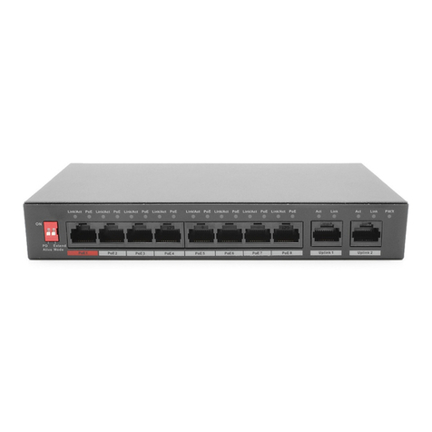
ICRealtime PWR-EPOE-8 User manual

8-Port ePoE Switch User’s Manual
V1.0.1

Important Safeguards and Warnings
Please read the following safeguards and warnings carefully before using the product in order to avoid
damages and losses.
Attentions:
Do not expose the device to lampblack, steam or dust. Otherwise it may cause fire or electric
shock.
Do not install the device at position exposed to sunlight or in high temperature. Temperature rise
in device may cause fire.
Do not expose the device to humid environment. Otherwise it may cause fire.
The device must be installed on solid and flat surface in order to guarantee safety under load and
earthquake. Otherwise, it may cause device to fall off or turnover.
Do not place the device on carpet or quilt.
Do not block air vent of the device or ventilation around the device. Otherwise, temperature in
device will rise and may cause fire.
Do not place any object on the device.
Do not disassemble the device without professional instruction.
Warning:
Please use battery properly to avoid fire, explosion and other dangers.
Please replace used battery with battery of the same type.
Do not use power line other than the one specified. Please use it properly. Otherwise, it may cause
fire or electric shock.
Special Announcement:
This manual is for reference only.
All the designs and software here are subject to change without prior written notice.
All trademarks and registered trademarks are the properties of their respective owners.
If there is any uncertainty or controversy, please refer to the final explanation of us.
Please visit our website for more information.

Table of Contents
1Product Overview............................................................................................. - 1 -
1.1 Product Introduction .........................................................................................................- 1 -
1.2 Features............................................................................................................................- 1 -
1.3 Typical Application............................................................................................................- 2 -
2Device Structure............................................................................................... - 3 -
2.1 Front Panel .......................................................................................................................- 3 -
2.2 Rear Panel........................................................................................................................- 4 -
2.3 PoE Power Supply............................................................................................................- 4 -
3Installation Guide ............................................................................................. - 5 -
4Appendix 1 ePoE Power Supply Specifications (CAT).................................. - 6 -
5Appendix 2 ePoE Power Supply Specifications (RG59 Coaxial Cable) ....... - 7 -

- 1 -
1 Product Overview
1.1 Product Introduction
8-Port ePoE Switch is a layer two hardened switch, which supports long distance Ethernet power supply.
It provides eight 10/100M Ethernet ports, one 1000M Ethernet port and one 1000M fiber port. The
product is equipped with three self-adaptive transmission modes which are IEEE, E100 and E10. It
supports both twisted-pair transmission and coaxial cable transmission.
1.2 Features
Common features:
Two-layer hardened PoE switch.
Support IEEE802.3, IEEE802.3u, IEEE802.3ab/z and IEEE802.3X standards.
MAC auto study and aging, MAC address list capacity is 4K.
Support MDI/MDIX self-adaptive.
Port 1-8 are RJ45 ports which support 10/100M self-adaptive; support IEEE802.3af, IEEE802.3at
standard power supply; Port 9 is RJ45 port which supports 10/100/1000M self-adaptive.
Industrial wide temperature design.
Adopt metal structure.
Support DC48-57V power supply.
Individual features:
The product owns one 1000M self-adaptive fiber port, one 10/100/1000M self-adaptive RJ45 port
and eight 10/100M self-adaptive RJ45 ports.
The number 1 port and 5 port support Hi-PoE 60W power supply.
It supports three transmission modes, which includes IEEE, E100 and E10. IEEE mode is the
standard Ethernet mode when it is transmitted via twisted-pair, which supports max transmission
distance up to 100m; E100 mode supports max transmission distance up to 300m and E10 mode
supports max transmission distance up to 800m. When it is transmitted via coaxial cable, IEEE
mode supports max transmission distance up to 100m, E100 mode supports max transmission
distance up to 400m and E10 mode supports max transmission distance up to 1000m.
The product adopts 120W power adapter.

- 2 -
1.3 Typical Application
Figure 1-1

- 3 -
2 Device Structure
2.1 Front Panel
The front panel is shown in Figure 2-1.
Figure 2-1
Refer to Table 2-1 for more details about the front panel.
SN
Name
Function
1
10/100 Base-T
8* 10/100M self-adaptive PoE power supply
ports
2
10/100/1000 Base-T
10/100/1000M self-adaptive RJ45 port
3
100/1000 Base-X
1000M self-adaptive fiber port.
4
Link / Act
Fiber port status indicator light.
5
PWR
Power indicator light, used as PoE power
supply status indicator light as well, refer to the
following sheet for more details.
Table 2-1

- 4 -
The power indicator light can display the current operation status of PoE power supply, which includes
three statuses: single port device power on, single port device power off and total device consumption
overload. Please refer to Table 2-2 for more details.
SN
Operation Status
Display Mode
1
Single port device power on
Slow flash twice
2
Single port device power off
Quick flash once, slow flash once
3
Total device consumption
overload
Quick flash twice
Table 2-2
Port indicator light is to display the status of current transmission mode for the port, which includes IEEE
mode, E100 and E10. Please refer to Table 2-3 for more details.
SN
Working mode
Indicator light display
1
IEEE mode
Normally on
2
E100
On for 3 seconds, off for 1 second
3
E10
On for 1 second, off for 1 second
Table 2-3
2.2 Rear Panel
The device power port is shown in Figure 2-2; it supports dual power input.
Figure 2-2
SN
Parameter
Note
1
PWR1
Support DC 48~57V
2
PWR2
Support DC 48~57V
3
Ground wire
2.3 PoE Power Supply
Six 100M RJ45 ports support IEEE802.3af, IEEE802.3at standard power supply.
Two 100M RJ45 port supports IEEE802.3af, IEEE802.3at standard and Hi-PoE 60W power supply.
Total power consumption of PoE device is not allowed to exceed the reserve value of device PoE
power consumption.

- 6 -
4 Appendix 1 ePoE Power Supply Specifications (CAT)
Cable Length
(m)
Communication
Bandwidth
(Mbps)
PoE Max Load
Capacity (W)
Hi-PoE Max
Load Capacity
(W)
Network
Operating
Mode
100
100
25.5
53
IEEE/E100
200
100
25.5
33
E100
300
100
19
19
E100
400
10
17
17
E10
500
10
13
13
E10
800
10
7
7
E10
ePoE switch supply voltage 48V.
CAT5E/CAT6, max. DC resistance < 10Ω/100m.
Cable Length
(m)
Communication
Bandwidth
(Mbps)
PoE Max Load
Capacity (W)
Hi-PoE Max
Load Capacity
(W)
Network
Operating
Mode
100
100
25.5
53
IEEE/E100
200
100
25.5
47
E100
300
100
25.5
32
E100
400
10
23
26
E10
500
10
20
20
E10
800
10
13
13
E10
ePoE switch supply voltage 53V.
CAT5E/CAT6, max. DC resistance < 10Ω/100m.

- 7 -
5 Appendix 2 ePoE Power Supply Specifications (RG59
Coaxial Cable)
Cable Length
(m)
Communication
Bandwidth
(Mbps)
PoE Max Load
Capacity (W)
Hi-PoE Max
Load Capacity
(W)
Network
Operating
Mode
100
100
25.5
50
IEEE/E100
200
100
25.5
30
E100
300
100
18
18
E100
400
100
15
15
E100
500
10
12
12
E10
800
10
6
6
E10
1000
10
5
5
E10
ePoE switch supply voltage 48V.
RG-59, max. DC resistance < 5Ω/100m.
100
100
25.5
52
IEEE/E100
200
100
25.5
48
E100
300
100
25.5
30
E100
400
100
20
23
E100
500
10
16
16
E10
800
10
10
10
E10
1000
10
8
8
E10
ePoE switch supply voltage 53V.
RG-59, max. DC resistance < 5Ω/100m.
Note
This user’s manual is for reference only.
Slight difference may be found in user interface.
All the designs and software here are subject to change without prior written notice.
All trademarks and registered trademarks are the properties of their respective owners.
If there is any uncertainty or controversy, please refer to the final explanation of us.
Please visit our website for more information.
Table of contents
Other ICRealtime Switch manuals