ICS 8099 User manual

ICS
ELECTRONICS
ICS
a division of Systems West Inc.
MODEL 8099
Ethernet Modbus Interface
Instruction Manual
8099
i
MODEL 8099
Ethernet Modbus Interface
Instruction Manual
7034 Commerce Circle, Pleasanton, CA 94588
Phone 925.416.1000, Fax 925.416.0105 Publication Number 120192
Web Site http://www.icselect.com November 2011 Edition Rev 2
ICS
ELECTRONICS
ICS
division of Systems West Inc.

ii
LIMITED WARRANTY
Within 12 months of delivery, ICS Electronics will repair or replace this product, at
our option, if any part is found to be defective in materials or workmanship (labor is
included). Return this product to ICS Electronics, or other designated repair station,
freight prepaid, for prompt repair or replacement. Contact ICS for a return material
authorization (RMA) number prior to returning the product for repair.
CERTIFICATION
ICS Electronics Corporation certifies that this product was carefully inspected and
tested at the factory prior to shipment and was found to meet all requirements of
the specification under which it was furnished.
EMI/RFI WARNING
This equipment generates, uses, and can radiate radio frequency energy and, if not
installed and used in accordance with the instruction manual, may cause interference
to radio communications. The Model 8099 has been tested and found to comply
with the limits for a Class A computing device pursuant to Subpart J of Part 15 of
the FCC Rules and to comply with the EEC Standards EEC Standards EN 61000-6-
4:2001, EN 61000-6-2:2001, EN 55024:2003, and EN 55022:2003, which are designed
to provide reasonable protection against such interference when operated in a com-
mercial environment. Operation of this equipment in a residential area is likely to
cause interference, in which case the user, at his own expense, will be required to
take whatever measures may be required to correct the interference.
Certificate of Conformance reproduced in Figure 1-2.
TRADEMARKS
The following trademarks referred to in this manual are the property of the fol-
lowing companies:
VEE is a trademark of Agilent, Palo Alto, CA
LabView is a Trademark of National istruments, Austin, TX
ICS and GPIB AnyWhere are trademarks of ICS Electronics, Pleasanton, CA
© 2010, 2011 ICS Electronics div of Systems West Inc.

i
General Information
Product Description, Model Numbers, VXI-11 Conformance, Ethernet
Interface, Digital Interface, Configurable Functions and Default Settings,
Indicators, Physical Specifications, Certifications and Accessories.
Installation
Shipment Verification, Installation Guide, Configuration Instructions,
Serial Connections, Internal Jumper Settings and Rack Mounting
Instructions.
Operation
Operation Description, Status Reporting Structure, IEEE-488.2
and SCPI Conformance, SCPI Commands, Modbus Commands,
Programming Guidelines, VXI-11 Keyboard, Error Logger Utility
and OEM Documentation.
Theory of Operation
Block Diagram Description
Maintenance, Troubleshooting and Repair
Maintenance, Troubleshooting Guide, Selftest Error Codes, Reverting
to Factory Settings, Updating Firmware, and Repair Information
Appendices
A1 IEEE-488.1, IEEE-488.2 and SCPI Descriptions
A2 VXI-11 Concept
A3 VXI-11 RPCgen Information
A4 ICS RPC Configuration Commands
Index
Contents
2
4
5
I
3
1
A

1-1
1
1
General Information
1.1 INTRODUCTION
This section provides a description and specifications for ICS's Model 8099
Ethernet to Modbus Interface. All specifications and functional descriptions
apply to all units unless otherwise stated.
1.2 DESCRIPTION
The Model 8099 Ethernet to Modbus Interface is a VXI-11.3 compliant in-
terface that provides RS-232 and RS-422/RS485 serial interfaces to control
Modbus devices using the Modbus RTU protocol. It lets the user send simple
commands with ASCII values over a 10/100 Mbs TCP/IP network to control
and query Modbus slave devices. The 8099 converts these simple commands
into the Modbus RTU packet protocol and adds the CRC checksum to make
a complete Modbus RTU packet. The Modbus RTU packets are sent serially
over a RS-232 link to a single Modbus slave device or over a RS-485 network
to one or multiple Modbus devices. Responses are checked and valid response
data from a query is returned when the 8099 is next addressed to talk.
The 8099 contains a number of advanced features that increase its flexibility
and simplifies their use in system applications. It is an IEEE-488.2 compatible
interface with an expanded Status Reporting Structure that complies with the
SCPI standard. SCPI commands are used to set the serial configuration, and
to enable bits in the Status Reporting Structure to generate Service Requests.
The user can also enter his own IDN message to personalize the unit as part
of his assembly. The 8099 contains a webserver which allows the user to
view and update the 8099's configuration settings. All settings are saved in
nonvolatile memory.

1-2
1
The 8099 is VXI-11.3 compliant which makes it easily controllable from virtu-
ally any computer with network access. One programming method is to make
program calls to a VISA or SICL library which can communicate with VXI-
11.3 instruments. LabView and VEE are graphical applications that can make
VISA calls. SICL or VISA calls are recommended for Visual Basic, C and other
program languages that can call any library. Another programming technique
is to use the RPC protocol to communicate with the 8099. The RPC protocol
makes it easy to control the 8099 from any LINUX/UNIX like environment.
JAVA programming examples are available on SourceForge.
The module contains a single instrument personality, inst0. inst0 is an IEEE-
488.2 compatible instrument and lets the user access the internal parser and
execute modbus commands to control the slave Modbus devices. The Ethernet
IP settings can be accessed by a web browser or by ICS's VXI-11 Configure
utility program. A 'LAN Reset' button allows the user to return the card to its
default IP settings at any time.
At power turn-on, the module's boot up and internal selftest process typically
takes approximately 4 seconds. At the end of the selftest, the 8099 turns the
RDY LED on if the test was successful. The LAN and ACT LEDs show the
status of the network connection. The TALK, LSTN and SRQ LEDs show
the module's current address status and if it has asserted a Service Request.
The ERR LED is momentarily illuminated when the card senses a soft error
condition or has a problem with a command that it received.
The 8099 conforms to the requirements for a LXI class C instrument per LXI
Standard Rev 1.1 with the exception of no support for auto-IP configuration. The
8064 exceeds the LXI specification for a class C instrument because it is fully
IEEE-488.2 compliant and specifies complete use of the VXI-11 protocol.
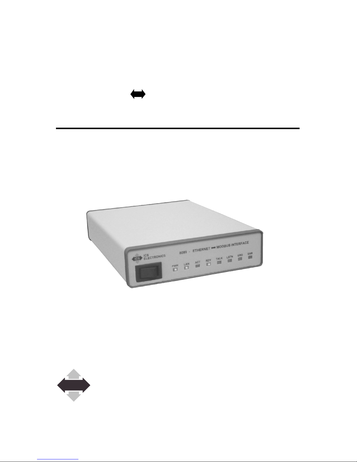
The Model 8099 is packaged in a small Minibox™ metal case that is less than
1U in height (1.6 inches) The front panel contains the power switch and LEDs
which indicate the unit's status. The rear panel contains the Ethernet and serial
connectors and a DC power jack. The 8099 accepts a wide range of DC volt-
ages and is shipped with an adapter for the local power lines.

1-3
1
1.3 MODEL SPECIFICATIONS
The following specifications apply to all 8099 models. Options for your unit
may be found by comparing the list below to those listed on the program label
on your unit.
8099 - X General Model Number
Option Codes
-6 Special settings
-7 Special Program
-8 Hardware modification
-9 Factory Rack Mounted
-A Ship with Australian 230 Vac Adapter
-B Ship with British 230 Vac Adapter
-E Ship with European 230 Vac Adapter
-U Ship with Universal 115/230 Vac Adapter

1-4
1
1.4. VXI-11 CONFORMANCE
The 8099 is a TCP/IP-IEEE 488.2 Instrument and complies with the VXI-11.3
Specification.
1.4.1 RPC Protocol
The RPC protocol conforms to ONC RPC Version 2.
1.4.2 Sockets
The 8099's VXI-11 service supports 15 TCP/IP sockets for client communica-
tion. The sockets are normally opened and closed by the clients. The unit will
close the socket and release all resources if a broken connection is detected or
when the link count goes to zero if Auto Disconnect is enabled.
There is a separate socket for UDP RPC Port Mapper communication.
1.4.3 Channels
Supports Core, Abort and Interrupt channels. Core and Abort channels each
use a socket connection. Core channels support up to 64 device links and locks.
A reverse Interrupt channel is a TCP/IP socket connection that does not count
against the 15 client communication sockets limit.
1.4.4 Device Links and Locks
The 8099 support a maximum of 64 device links and 64 locks that can be used
over multiple Core channels by one or more clients.
1.4.5 VXI-11 Interface Name
The 8064 has only one instrument personality and the default name is inst0.
The name may be changed to any 8 character string.
1.4.6 VXI-11.3 Supported Functions
The 8099 supports all VXI-11.3 functions including:
create_link destroy_link create_intr_channel destroy_intr_channel
device_lock device_unlock device_abort
device_read device_write device_clear device_trigger
device_remote device_local device_readstb create_intr_channel
device_intr_SRQ device_enable_SRQ

1-5
1
1.5 ETHERNET INTERFACE
1.5.1 Type
IEEE-802.3 Compliant
1.5.2 Speed
Auto speed sensing, 10 Mbs with 10BaseT and 100 Mbs with 100BaseT
1.5.3 Network Address
Static: IP Address, Subnet Mask, and Gateway IPv4 values are user set from
0.0.0.0 to 255.255.255.255. Default values are listed in Table 1-3.
DHCP: Accepts IPv4 address from a DHCP Server.
1.5.4 KeepAlive Message
User enabled. Message sent if no activity for 120 minutes.
1.5.5 COMM Timeout
User set period, 0 to 232 seconds, to release socket resources if no activity.
1.5.6 Port Usage
TABLE 1-1 8099 PORT USAGE
Port Usage Protocols Notes
80 Internal WebServer TCP Web Browser access
111 RPC Port Mapper UDP, TCP
5555 Core Channel TCP
2000-2999 Abort Channel TCP Assigned when opened
xxxx Reverse Notification TCP Defined by client
5556 Configuration Port, TCP
Error Logger
1.5.7 Protocols
TCP/IP for VXI-11, HTTP and RPC communication
UPD and TCP/IP for RPC Port Mapper commands

1-6
1
TABLE 1-2 FACTORY NETWORK SETTINGS
Command
Function Choices Default Source (1)
IP Address Mode Static or Dynamic Static E
IP Address 0.0.0.0 to 192.168.0.254 E
255.255.255.255
Net Mask 0.0.0.0 to 255.255.255.0 E
255.255.255.255
Gateway IP 0.0.0.0 to 192.168.0.1 E
255.255.255.255
COMM Timeout 120 sec E
IP KeepAlive On or Off On E
Interface Name Any string(4) inst0 E
REN state at On or Off On E
power turn-on
Auto Disconnect On or Off Off E
Sockets
Notes: 1. E = Ethernet Interface
2. Function definitions are described in Table 2-1
3. The 8099's MAC Address is factory set and is not user changeable. The
MAC Address can be read with the VXI-11 Configuration Utility or
with a web Browser.
4. Changing the interface name may cause your application to stop work-
ing.
5. Setting Auto Disconnect on may cause your application to loose its
connection to the 8099.
Table of contents
Other ICS Recording Equipment manuals


