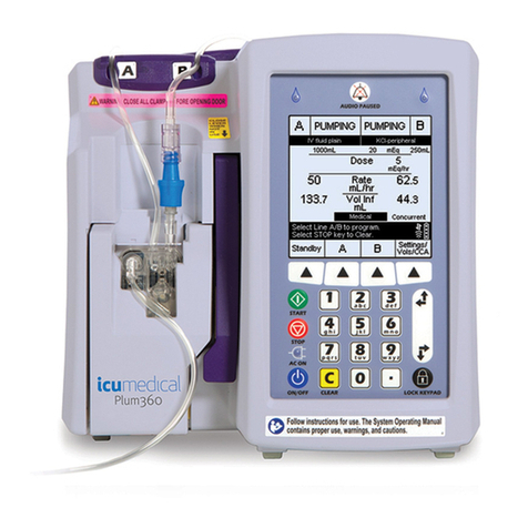
ICU Medical LifeCare PCA Operating manual

LifeCare PCA
™
ICU Medical, Inc.
600 N. Field Drive
Lake Forest, Illinois, 60045
USA
430-97357-004 (A, 2018-06)
Technical Service Manual
Compatible with:
ICU Medical MedNet
™
For use with list number 20837-04 and
list number 20709-04 upgraded with 7.x software
Infuser

LifeCare PCA Technical Service Manual
This page intentionally left blank.

Technical Service Manual i LifeCare PCA
Change History
Part Number Description of Change
430-97357-004
(A, 2018-06)
Updated product list number (Section 1.9)
430-97357-003
(A, 2017-09)
Updated entire manual to reflect new ICU Medical corporate
identity.
430-97357-002
(A, 2017-01)
Updated cleaning and disinfecting instructions throughout
the manual
Updated contact information throughout the manual
Clarified references to the lithium coin cell battery
throughout the manual
Updated references to the start-up sequence throughout the
manual
Added information for handling a suspected cybersecurity
event or threat (Section 1)
Updated the Preventive Maintenance/Performance
Verification Test Checklist (Section 5)
Added information on the Battery Charger (Section 5)

CHANGE HISTORY
Technical Service Manual ii LifeCare PCA
This page intentionally left blank.

Technical Service Manual iii LifeCare PCA
Contents
Section1
INTRODUCTION .......................... 1‐1
1.1 LISTNUMBER20709‐04UPGRADEDTO7.X SOFTWARE........ 1‐1
1.2 SCOPE........................... 1‐1
1.3 CONVENTIONS....................... 1‐2
1.4 COMPONENTDESIGNATORS................. 1‐3
1.5 ACRONYMSANDABBREVIATIONS ............... 1‐3
1.6 USERQUALIFICATION .................... 1‐5
1.7 ARTIFACTS......................... 1‐5
1.8 ELECTROMAGNETICCOMPATIBILITY .............. 1‐5
1.9 FCCINFORMATION..................... 1‐6
1.10 INFUSIONSYSTEMINSTALLATION............... 1‐6
1.10.1 UNPACKING..................... 1‐6
1.10.2 INSPECTION..................... 1‐6
1.10.3 SELFTEST ...................... 1‐7
1.10.4 SETTINGTHETIMEANDDATE .............. 1‐8
1.10.5 SETTING/CHANGINGTHEALARMVOLUME......... 1‐9
1.10.6 CLEANINGPRIORTOFIRSTUSE.............1‐10
1.11 SUSPECTEDCYBERSECURITYEVENTORTHREAT.........1‐10
Section2
WARRANTY............................ 2‐1
Section3
SYSTEMOPERATINGMANUAL .................... 3‐1
Section4
INFORMATIONFORLEGACYLIFECAREPCAINFUSERSUPGRADED
WITH7.X SOFTWARE ........................ 4‐1
4.1 IEC60601‐1COMPLIANCE................... 4‐2
4.2 IEC 60601‐1‐2COMPLIANCE .................. 4‐2
4.3 FLUIDINGRESSPROTECTIONRATING.............. 4‐2
4.4 SPECIFICATIONS ...................... 4‐2
4.5 FUSEINFORMATION..................... 4‐3
4.6 OCCLUSIONTEST...................... 4‐3
4.7 OCCLUSIONALARMSWITCHTESTANDADJUSTMENT....... 4‐3
4.7.1 OCCLUSIONALARMSWITCHTEST............ 4‐4
4.7.2 OCCLUSIONALARMSWITCHANDPRESSUREADJUSTMENT.. 4‐5
4.8 PATIENTPENDANTJACKASSEMBLYREPLACEMENT........ 4‐7
4.9 CSAMARK......................... 4‐7
Section5
MAINTENANCEANDSERVICETESTS .................. 5‐1
5.1 CLEANINGANDDISINFECTION ................ 5‐1
5.2 CLEANING......................... 5‐2
5.2.1 APPROVEDCLEANINGSOLUTIONS............ 5‐2
5.2.2 CLEANINGSUPPLIES .................. 5‐3
5.2.3 PREPARINGTHEINFUSERFORCLEANING ......... 5‐3
5.2.4 GENERALCLEANINGINSTRUCTIONS ........... 5‐3
5.2.5 CLEANINGEXTERIORSURFACES ............. 5‐4
5.2.6 CLEANINGTHEVIALCOMPARTMENT ........... 5‐8
5.2.6.1 CLEANINGTHEINJECTORSWITCHPIN .......5‐10

CONTENTS
LifeCare PCA iv Technical Service Manual
5.2.7 CLEANINGTHEPOWERCORDSTRAP ...........5‐11
5.2.8 CLEANINGTHEPATIENTPENDANTSTRAP .........5‐11
5.2.9 CLEANINGINFUSERACCESSORIES ............5‐11
5.2.10 RINSINGTHEINFUSER .................5‐12
5.2.11 DRYINGTHEINFUSER.................5‐12
5.2.12 CLEANINGSPILLSDURINGTHECOURSEOFPATIENTCARE ..5‐12
5.3 DISINFECTION .......................5‐13
5.3.1 APPROVEDDISINFECTIONSOLUTIONS..........5‐13
5.3.2 DISINFECTIONSUPPLIES ................5‐14
5.3.3 PREPARINGTHEINFUSERFORDISINFECTION .......5‐14
5.3.4 GENERALDISINFECTIONINSTRUCTIONS.........5‐14
5.3.5 DISINFECTINGEXTERIORSURFACES ...........5‐15
5.3.6 DISINFECTINGTHEVIALCOMPARTMENT .........5‐16
5.3.7 DISINFECTINGTHEPOWERCORDSTRAP .........5‐17
5.3.8 DISINFECTINGTHEPATIENTPENDANTSTRAP.......5‐17
5.3.9 DISINFECTINGACCESSORIES..............5‐17
5.3.10 RINSINGTHEINFUSER .................5‐17
5.3.11 DRYINGTHEINFUSER.................5‐17
5.4 PRODUCTHANDLINGANDDISPOSAL .............5‐18
5.5 PREVENTIVEMAINTENANCE .................5‐19
5.5.1 PM/PVTCHECKLIST..................5‐20
5.5.2 LABELSINSPECTION..................5‐21
5.5.3 ACPOWERCORDINSPECTIONANDTEST.........5‐23
5.5.4 FRONTENCLOSURE,REARENCLOSURE,CRADLEASSEMBLY,
ANDSECURITYDOORINSPECTIONAND TEST .......5‐25
5.5.5 RUBBERFOOTPADINSPECTION .............5‐27
5.5.6 POLECLAMPASSEMBLYINSPECTIONANDTEST.......5‐28
5.5.7 KEYPAD,DISPLAYS(LED/LCD),ANDINDICATORS
INSPECTION....................5‐29
5.5.8 PATIENTPENDANTINSPECTION .............5‐31
5.5.9 BARCODEREADERWINDOWINSPECTION,TEST,
ANDCLEANING ...................5‐32
5.6 PERFORMANCEVERIFICATIONTEST..............5‐34
5.6.1 REQUIREDEQUIPMENT .................5‐34
5.6.2 TESTSETUP.....................5‐35
5.6.3 STUCKINJECTORSWITCHPINTEST ............5‐35
5.6.4 SELFTEST......................5‐36
5.6.5 BIOMEDMODETESTS .................5‐38
5.6.6 DELIVERYACCURACYTEST...............5‐39
5.6.6.1 DELIVERYACCURACYTEST(ALTERNATEMETHOD)..5‐41
5.6.7 OCCLUSIONTEST...................5‐41
5.6.8 ELECTRICALSAFETYTEST................5‐41
5.6.9 ENDOFTHEPVT...................5‐42
5.7 NETWORKCONNECTIVITYCHECKS...............5‐43
5.8 BATTERYOPERATIONOVERVIEW...............5‐46
5.9 BATTERYCHARGER.....................5‐46
Section6
TROUBLESHOOTING........................6‐1
6.1 TECHNICALASSISTANCE...................6‐1
6.2 DIAGNOSTICMODE .....................6‐2
6.3 ALARMMESSAGESANDERRORCODES .............6‐2
6.3.1 OPERATIONALALARMMESSAGES............6‐3
6.3.2 ERRORCODESREQUIRINGTECHNICALSERVICE......6‐6
6.4 TROUBLESHOOTINGPROCEDURES...............6‐12

CONTENTS
Technical Service Manual v LifeCare PCA
Section7
REPLACEABLEPARTSAND REPAIRS .................. 7‐1
7.1 REPLACEABLEPARTS..................... 7‐1
7.2 ADJUSTMENTPROCEDURES.................. 7‐1
7.2.1 REQUIREDTOOLSANDMATERIALS ............ 7‐2
7.2.2 SEPARATINGTHEFRONTANDREARENCLOSURES ...... 7‐2
7.2.3 INJECTORSENSORSWITCHADJUSTMENT......... 7‐3
7.2.4 VIALSENSORSWITCHADJUSTMENT ........... 7‐4
7.2.5 OCCLUSIONALARMSWITCHADJUSTMENT......... 7‐5
7.3 REPLACEMENTPROCEDURES ................. 7‐6
7.3.1 SAFETYANDEQUIPMENTPRECAUTIONS .......... 7‐6
7.3.2 REQUIREDTOOLSANDMATERIALS ............ 7‐6
7.3.3 FRONTANDREARENCLOSUREREPLACEMENT ....... 7‐7
7.3.4 RUBBERFOOTPADREPLACEMENT............ 7‐8
7.3.5 ACPOWERCORDREPLACEMENT ............. 7‐9
7.3.6 BATTERY,BATTERYDOOR,DOORPAD,AND
BATTERYSTRAPREPLACEMENT............. 7‐9
7.3.7 PATIENTPENDANTASSEMBLYREPLACEMENT.......7‐11
7.3.8 FRONTENCLOSUREASSEMBLYCOMPONENTREPLACEMENT .7‐11
7.3.8.1 SECURITYDOORANDDOORHINGEREPLACEMENT..7‐12
7.3.8.2 KEYPADREPLACEMENT.............7‐14
7.3.8.3 DOORLATCHHOOKREPLACEMENT........7‐15
7.3.8.4 CRADLEASSEMBLYREPLACEMENT........7‐15
7.3.8.5 MECHANISMLEVERARMREPLACEMENT......7‐16
7.3.8.6 DOORLATCHASSEMBLYREPLACEMENT ......7‐17
7.3.8.7 DOORLOCKASSEMBLYREPLACEMENT .......7‐18
7.3.8.8 HANDLEGASKETANDENCLOSUREGASKET
REPLACEMENT.................7‐19
7.3.8.9 REMOVINGTHECEPWA.............7‐20
7.3.8.10 REMOVINGTHEELECTRONICSASSEMBLY .....7‐22
7.3.8.11 ANTENNAPWAREPLACEMENT..........7‐23
7.3.8.12 ELECTRONICSASSEMBLYCOMPONENT
REPLACEMENT................. 7‐24
7.3.8.13 LCDWINDOWREPLACEMENT...........7‐28
7.3.8.14 MECHANISMASSEMBLYREPLACEMENT......7‐29
7.3.8.15 BARCODEREADER,GASKET,ANDWINDOW
REPLACEMENT................ 7‐30
7.3.8.16 SPLASHSHIELDREPLACEMENT ..........7‐31
7.3.9 REARENCLOSUREASSEMBLYCOMPONENTREPLACEMENT ..7‐31
7.3.9.1 FUSEREPLACEMENT..............7‐32
7.3.9.2 POLECLAMPASSEMBLYREPLACEMENT ......7‐33
7.3.9.3 VELCROSTRAPANDRETAINERPLATE
REPLACEMENT.................7‐34
7.3.9.4 POWERSUPPLYPWAREPLACEMENT........7‐35
7.3.9.5 PAWL/RATCHETASSEMBLYREPLACEMENT.....7‐35
7.3.9.6 REARENCLOSUREHARNESSASSEMBLY,
EQUIPOTENTIALPOST,ANDGROUNDSTRAP
REPLACEMENT.................7‐36
7.3.9.7 I/OPWAREPLACEMENT .............7‐37
7.3.9.8 BATTERYPADREPLACEMENT...........7‐38
7.3.9.9 PATIENTPENDANTJACKASSEMBLYREPLACEMENT .7‐39
Section8
SPECIFICATIONS .......................... 8‐1

CONTENTS
Technical Service Manual vii LifeCare PCA
Figures
Figure1‐1 LifeCarePCASelfTestScreens.................... 1‐7
Figure1‐2SettingtheTimeandDate ...................... 1‐9
Figure4‐1 OcclusionAlarmTestSetup...................... 4‐5
Figure4‐2 OcclusionAlarmPressureAdjustment................. 4‐6
Figure5‐1BottomView‐CleaningtheBottomoftheInfuser ............ 5‐5
Figure5‐2RearView‐CleaningtheBackofInfuser ................ 5‐6
Figure5‐3FrontView‐CleaningtheKeypad................... 5‐7
Figure5‐4FrontView‐CleaningtheVialDoor.................. 5‐8
Figure5‐5FrontView‐CleaningtheVialCompartment.............. 5‐9
Figure5‐6InjectorSwitchPinLocation .....................5‐10
Figure5‐7ExampleofInjectorSwitchPinWithAccumulatedFluidSpillage
(viewfromthetopoftheflange)...................5‐10
Figure5‐8 LifeCarePCAInfuserLabels.....................5‐22
Figure5‐9ACPowerCordAssembly ......................5‐24
Figure5‐10 FrontEnclosureandRearEnclosure ..................5‐26
Figure5‐11 RubberFootPads..........................5‐27
Figure5‐12 PoleClampAssembly........................5‐28
Figure5‐13 Keypad,Displays,andIndicators ...................5‐30
Figure5‐14 PatientPendant ...........................5‐31
Figure5‐15 BarcodeReaderAssembly ......................5‐33
Figure5‐16 Vial/InjectorPositionforStuckInjectorSwitchPinTest .........5‐36
Figure5‐17 LifeCarePCASelfTestScreens....................5‐37
Figure5‐18 EthernetConnectivity ........................5‐43
Figure5‐19 History/BatteryStatusScreen .....................5‐44
Figure5‐20 WaitingforAuto‐ProgramScreen...................5‐44
Figure5‐21 UnabletoAuto‐ProgramScreen....................5‐45
Figure7‐1 SeparatingtheFrontandRearEnclosureAssemblies .......... 7‐3
Figure7‐2InjectorSensorSwitch........................ 7‐4
Figure7‐3VialSensorSwitch .......................... 7‐5
Figure7‐4BatteryAssembly,ACPowerCord,andPatientPendantAssembly .... 7‐8
Figure7‐5FrontEnclosureAssemblyExternalComponents............7‐13
Figure7‐6FrontEnclosureAssemblyInternalComponents ............7‐17
Figure7‐7DoorLockAssembly.........................7‐19
Figure7‐8RemovingtheCEPWA........................7‐21
Figure7‐9 InstallingtheCEPWA........................7‐21
Figure7‐10 AntennaPWAReplacement ......................7‐23
Figure7‐11 ElectronicsAssemblyComponents...................7‐24
Figure7‐12 RearEnclosureExternalComponents .................7‐32
Figure7‐13 RearEnclosureHarnessAssembly...................7‐38
Figure7‐14 RearEnclosureInternalComponents..................7‐40
Figure9‐1 IllustratedPartsBreakdown(Sheet1of2) ............... 9‐5
Figure9‐2 IllustratedPartsBreakdown(Sheet2of2) ............... 9‐6

CONTENTS
LifeCare PCA viii Technical Service Manual
Tables
Table1‐1 Conventions .......................1‐2
Table4‐1SectionReferenceforUpgradedPumps.............4‐1
Table5‐1 CleaningSolutions .....................5‐2
Table5‐2 CleaningMethods.....................5‐3
Table5‐3TimeIntervalsforCleaning..................5‐4
Table5‐4 DisinfectingSolutions ...................5‐13
Table5‐5 DisinfectionMethods ....................5‐14
Table5‐6MinimumTimeIntervalsforDisinfecting............5‐15
Table5‐7SystemTests.......................5‐38
Table5‐8 ElectricalSafetyMeasurements ................5‐42
Table6‐1OperationalAlarmMessages .................6‐3
Table6‐2ErrorCodesRequiringTechnicalService .............6‐6
Table6‐3 TroubleshootingwiththePVT ................6‐12
Table9‐1IllustratedPartsBreakdown .................9‐1
TableA‐1 GuidanceandManufacturer’sDeclaration‐ElectromagneticEmissions ..A‐1
TableA‐2 GuidanceandManufacturer’sDeclaration‐ElectromagneticImmunity..A‐2
TableA‐3 GuidanceandManufacturer’sDeclaration‐ElectromagneticImmunity
forMEEquipmentandMESystemsthatarenotLife‐Supporting....A‐3
TableA‐4 RecommendedSeparationDistancesBetweenPortableandMobile
RFCommunicationsEquipmentandtheInfusionSystem.......A‐5

Technical Service Manual 1 - 1 LifeCare PCA
Section1
INTRODUCTION
The LifeCare PCA™with ICU Medical MedNet™Software is a patient-controlled analgesia
management system designed to meet the fluid delivery requirements of today’s evolving
healthcare environments. The system is comprised of a pole mounted or tabletop drug
infuser (LifeCare PCA), barcoded drug vials with a variety of pre-filled drugs and drug
concentrations (LifeCare PCA vial), and compatible administration sets.
The LifeCare PCA is a self-contained, microprocessor-based infusion device that features
keypad controls, a prompting alphanumeric display, an LED display, an integral locking
system, a pole clamp, a barcode reader designed to automate drug identification,
and field-upgradeable software.
The device contains a Connectivity Engine (CE) that provides wired Ethernet
communication and wireless communication via WiFi protocol 802.11 a/b/g.
ICU Medical MedNet networked application software allows a facility to customize
and download a Drug Library for use with the infusion system. Before using the software,
see the
ICU Medical MedNet
™
Software User Guide
.
The infusion system is intended to operate on AC power. An internal battery is provided
to maintain operation for short periods of time during patient transport and when
AC power is lost or not available.
1.1
LISTNUMBER20709‐04UPGRADEDTO
7.X SOFTWARE
Legacy LifeCare PCA infusion systems list number 20709-04 upgraded to 7.x software are
substantially equivalent with list number 20837. Any differences associated with list
number 20709-04 upgraded to 7.x software are documented in
Section 4, Information for
Legacy LifeCare PCA Infusers Upgraded with 7.x Software
.
1.2
SCOPE
This manual is organized into the following sections:
❏Section 1 Introduction
❏Section 2 Warranty
❏Section 3 System Operating Manual
❏Section 4 Information for Legacy LifeCare PCA Infusers Upgraded with
7.x Software
❏Section 5 Maintenance and Service Tests
❏Section 6 Troubleshooting

SECTION 1 INTRODUCTION
LifeCare PCA 1 - 2 Technical Service Manual
❏Section 7 Replaceable Parts and Repairs
❏Section 8 Specifications
❏Section 9 Drawings
❏Appendices
If a problem in device operation cannot be resolved using the information in this manual,
contact ICU Medical
(see Section 6.1)
.
Specific instructions for operating the device are contained in its respective
System
Operating Manual
.
The terms “infusion system”, “infuser”, and “device” are used interchangeably throughout
the manual.
Figures are rendered as graphic representations to approximate actual product.
Therefore, figures may not exactly reflect the product. Screen representations
are examples only, and do not necessarily reflect the most current configuration.
1.3
CONVENTIONS
The conventions listed in
Table 1-1
are used throughout this manual.
Throughout this manual, warnings, cautions, and notes are used to emphasize important
information, as follows:
Note: A note highlights information that helps explain a concept or procedure.
Table 1-1. Conventions
Convention Application Example
Italic Reference to a section, figure,
table, website, or publication
(see Section 6.1)
[ALL CAPS]
ALL CAPS
In-text references to keys,
touchswitches, and display
messages
[START]
LOW BATTERY
Bold Emphasis CAUTION: Use proper ESD grounding
techniques when handling components.
Screen displays Select Set Time and Date.
WARNING: A WARNING CONTAINS SPECIAL SAFETY EMPHASIS AND MUST
BE OBSERVED AT ALL TIMES. FAILURE TO OBSERVE A WARNING MAY RESULT
IN PATIENT INJURY AND BE LIFE-THREATENING.
CAUTION: A CAUTION usually appears in front of a procedure or statement.
It contains information that could prevent hardware failure, irreversible
damage to equipment, or loss of data.

1.4 COMPONENT DESIGNATORS
Technical Service Manual 1 - 3 LifeCare PCA
1.4
COMPONENTDESIGNATORS
Components are indicated by alpha-numeric designators, as follows:
The number following the letter is a unique value for each type of component (e.g., R1, R2).
Note: Alpha-numeric designators may be followed with a dash (-) number that
indicates a pin number for that component. For example, U15-13 is pin 13
of the encoder chip [U15] on the interface PWA.
1.5
ACRONYMSANDABBREVIATIONS
Acronyms and abbreviations used in this manual are as follows:
AAmpere
AC Alternating current
ADC Analog-to-digital converter
BCR Barcode reader
CE Connectivity engine
CMOS Complementary metal-oxide semiconductor
CPU Central processing unit
dB Decibel
DC Direct current
DPM Digital pressure meter
DSLR Display start line register
ECG Electrocardiograph
EEG Electroencephalogram
EMC Electromagnetic compatibility
EMG Electromyogram
EMI Electromagnetic interference
EPROM Erasable/programmable read-only memory
ESD Electrostatic discharge
ETO Ethylene oxide
hr Hour
Hz Hertz
ID Identification
I/O Input/output
Battery BT Diode DResistor R
Capacitor CFuse FSwitch SW
Crystal YIntegrated Circuit UTransistor Q

SECTION 1 INTRODUCTION
LifeCare PCA 1 - 4 Technical Service Manual
IPB Illustrated parts breakdown
IV Intravenous
lbs Pounds
LCD Liquid crystal display
LED Light emitting diode
mA Milliampere
mcg Microgram
MCU Microcontroller unit
mg Milligram
mL Milliliter
MPU Microprocessor unit
ms Millisecond
ns nanosecond
PCA Patient controlled analgesia
PCL Power control logic
psi Pounds per square inch
PVT Performance verification test
PWA Printed wiring assembly
RAM Random access memory
ROM Read only memory
RTC Real-time clock
SLA Sealed lead acid
SPDT Single pole double throw
SPI Serial peripheral interface
SRAM Static random access memory
UART Universal asynchronous receiver transmitter
VVolt
VAC Volts alternating current
VCC Collector supply voltage
VDC Volts DC
VTBI Volume to be infused
WDI Watchdog input
AMicroampere
VMicrovolt

1.6 USER QUALIFICATION
Technical Service Manual 1 - 5 LifeCare PCA
1.6
USERQUALIFICATION
The LifeCare PCA with ICU Medical MedNet infusion system is intended for use at the
direction or under the supervision of licensed physicians or certified health care
professionals who are trained in the use of the pump and the administration of parenteral
and epidural fluids and drugs and the corresponding warnings and precautions. Training
should emphasize the assessment and monitoring of patients receiving potent analgesic
medications, and appropriate treatment for possible adverse reactions.
1.7
ARTIFACTS
Nonhazardous, low-level electrical potentials are commonly observed when fluids
are administered using infusion devices. These potentials are well within accepted safety
standards, but may create artifacts on voltage-sensing equipment such as ECG, EMG,
and EEG machines. These artifacts vary at a rate that is associated with the infusion rate.
If the monitoring machine is not operating correctly or has loose or defective connections
to its sensing electrodes, these artifacts may be accentuated so as to simulate actual
physiological signals.
To determine if the abnormality in the monitoring equipment is caused by the infuser
instead of some other source in the environment, set the device so that it is temporarily
not delivering fluid. Disappearance of the abnormality indicates that it was probably
caused by electronic noise generated by the infuser. Proper setup and maintenance
of the monitoring equipment should eliminate the artifact. Refer to the appropriate
monitoring system documentation for setup and maintenance instructions.
1.8
ELECTROMAGNETICCOMPATIBILITY
The LifeCare PCA has been tested and found to comply with electromagnetic compatibility
(EMC) limits as specified in IEC 60601-1-2:2007. These limits are designed to provide
reasonable protection against harmful interference in a typical medical installation.
The equipment generates, uses, and may radiate radio frequency energy if not installed
and used in accordance with the instructions. It may interfere with other devices
in the vicinity
(see the System Operating Manual)
.
There is a shared responsibility between manufacturers, customers, and users to assure
that medical equipment and systems are designed and operated as intended.
Medical electrical equipment requires special precautions regarding electromagnetic
compatibility.
CAUTION: Portable and mobile RF communications equipment, such as
cellular telephones, two-way radios, Bluetooth™devices, and microwave ovens
in close proximity to the infusion system may affect wireless and wired
communications and degrade performance of the system. Operation of the
infuser under such conditions should be avoided.

SECTION 1 INTRODUCTION
LifeCare PCA 1 - 6 Technical Service Manual
The electromagnetic environment should be managed to permit the infusion system
to perform as intended without disturbing other equipment. The infusion system should
not be used adjacent to or stacked with other equipment. If the device must be used
adjacent to or stacked with other equipment, monitor the equipment to assure there is no
electromagnetic interference, and verify normal infuser operation.
Use of a shielded Ethernet cable (CAT5 STP or better) for plugging into the RJ-45 connector
is required. Using an unshielded Ethernet cable may result in increased emissions.
1.9
FCCINFORMATION
The LifeCare PCA has been tested and found to comply with the Class B limits for list
number 20837-04 Class a/b/g digital devices, pursuant to Part 15 of the FCC rules. These
limits are designed to provide reasonable protection against harmful interference.
The wireless LAN device in the connectivity engine has been evaluated and found to be
compliant with the requirements of FCC radio frequency exposure standards
(see the System Operating Manual).
1.10
INFUSIONSYSTEMINSTALLATION
Accessory equipment connected to the analog and digital interfaces must be certified
according to the respective IEC standards (e.g., IEC 60601-1 for medical equipment). If in
doubt, contact ICU Medical.
Infusion system installation consists of unpacking, inspection, self test, and setting
the time and date.
1.10.1
UNPACKING
Inspect the shipping container as detailed in Section 1.10.2. Use care when unpacking
the infusion system. Retain the packing slip and save all packing material in the event
it is necessary to return the infuser to the factory. Verify the shipping container contains
acopyoftheSystem Operating Manual.
1.10.2
INSPECTION
Inspect the shipping container for damage. Should any damage be found, contact
the delivering carrier immediately.
Inspect the infusion system periodically for signs of defects such as worn accessories,
broken connections, or damaged cable assemblies. Also inspect the infuser after repair
or during cleaning. Replace any damaged or defective external parts.
CAUTION: Infusion system damage may occur unless proper care is exercised
during product unpacking and installation. The battery may not be fully
charged upon receipt of the infuser.
CAUTION: Inspect the infuser for evidence of damage. Do not use the device
if it appears to be damaged. Should damage be found, contact ICU Medical.

1.10 INFUSION SYSTEM INSTALLATION
Technical Service Manual 1 - 7 LifeCare PCA
1.10.3
SELFTEST
If an alarm condition occurs during the self test, cycle the power and repeat the self test.
If the alarm condition recurs, note the message and take corrective action (see Section 6).
Repeat the self test. If the alarm condition continues to recur, remove the infuser from
service and contact ICU Medical.
Note: Do not place the infuser in service if the battery is not fully charged. To make
certain the battery is fully charged, connect the infuser to AC power for 16 hours.
Note: When plugging the device into an AC power outlet, grasp the AC power cord
plug and use a forward motion into the socket. Do not use a sideways motion. When
unplugging the device, grasp the AC power cord plug and pull straight out. Do not
pull out using the power cord cable and do not pull out at an angle.
To perform the self test, see Figure 1-1, and proceed as follows:
1. Unlock and open the security door.
2. Plug the AC power cord into a grounded hospital grade, 120 VAC, 50-60 Hz
receptacle. Verify the AC plug indicator on the front panel is illuminated.
Note: If the quality of earth grounding source is in doubt, use battery power.
Note: When the AC plug indicator is off and the battery indicator on the display
is flashing, it is an indication that the infuser is operating on low battery
power and should be recharged.
3. Press [ON/OFF] to turn on the power. The infuser will perform a self test verifying
the integrity of the software, memory, and selected electronic functions.
4. Verify the time and date. To set the time and date, see Section 1.10.4.
Figure 1-1. LifeCare PCA Self Test Screens
Note: If the infuser is running 7.02 software or higher, the Software Version screen
will display instead of the Self Test Complete screen, and will automatically transition
to the next screen after 5 seconds. Select SETTINGS> on this screen to view the Select
Setting to Change menu and set the time and date.
CAUTION: Do not place the infuser in service if the self test fails.
LifeCare PCA
SELF TEST
LifeCare PCA
SELF TEST
SOFTWARE
07.00.00.019
DRUG LIBRARY
DEFAULT
TIME: 11:13 AM
DATE: 07/21/14
SYSTEM
SETTINGS
CONTINUE
LifeCare PCA
SELF TEST
COMPLETE
RAM.............OK
FLASH..........OK
CPU ID.........OK
CPU..............OK
TIMER......... OK

SECTION 1 INTRODUCTION
LifeCare PCA 1 - 8 Technical Service Manual
1.10.4
SETTINGTHETIMEANDDATE
To set the time and date, see
Figure 1-2
, and proceed as follows:
1. Unlock and open the security door.
2. Press [ON/OFF] to turn on the power, and wait for the SELF TEST COMPLETE screen
to appear.
3. Press the [SYSTEM SETTINGS] softkey, then press the [TIME/DATE] softkey.
Note: If the infuser is running 7.02 software or higher, the Software Version screen
will display instead of the Self Test Complete screen, and will automatically
transition to the next screen after 5 seconds. Select SETTINGS> on this
screen to view the Select Setting to Change menu and press the [TIME/
DATE] softkey.
The screen displays WARNING! CHANGING THE DATE OR TIME WILL CLEAR ALL
TOTALS!
4. Press the [CONTINUE] softkey.
5. Set the time using the keypad touchswitches. Press the [AM/PM] softkey to toggle
AM/PM.
Note: AM/PM option is available only in 12-hour clock format.
6. Press the [NEXT] softkey to continue.
7. Set the date using the keypad touchswitches, then press the [NEXT] softkey.
8. Press the [CONFIRM] softkey to accept current time and date settings, or press
[CHANGE] to change time or date settings.
9. Verify the SAVING DATE AND TIME screen is displayed.
10. Verify the SELECT SETTING TO CHANGE screen is displayed.
11. Press the [ON/OFF] softkey when correct time and date are displayed.

1.10 INFUSION SYSTEM INSTALLATION
Technical Service Manual 1 - 9 LifeCare PCA
Figure 1-2. Setting the Time and Date
1.10.5
SETTING/CHANGINGTHEALARMVOLUME
The infuser is shipped with its alarm volume set to High, which is its maximum alarm
volume level.
To set the default alarm volume, proceed as follows:
1. Confirm the AC power indicator on the front panel is lit.
2. Unlock and open the security door.
3. Enter Biomed Mode by pressing and holding [ENTER] and [ON/OFF]
simultaneously.
4. Verify the BIOMED MODE screen displays.
5. Verify the infusion system is not connected to a patient and press [CONTINUE].
6. After the power up RAM test is completed, the infuser displays the Biomed Mode
Main Menu screen. Press the [MAINTENANCE] softkey.
7. Press the [SET VOLUME] softkey.
WARNING: CHECK THAT THE ALARM VOLUME LEVEL IS APPROPRIATE FOR THE
CURRENT PATIENT AND BACKGROUND NOISE LEVEL BEFORE USE ON THE
PATIENT.
CAUTION: Setting the alarm volume to Low will result in an audible alarm
volume below the 45 dBA minumum specified by IEC60601-2-24.
SELECT
SETTING
TO CHANGE
CONTRAST
TIME/DATE
CONTINUE
SELECT TIME
WITH NUMBER
BUTTONS
TOGGLE AM/PM
10:43 PM
AM/PM
NEXT
WARNING!
CHANGING THE
DATE OR TIME
WILL CLEAR ALL
TOTALS!
CONTINUE
PREVIOUS
SET DATE WITH
NUMBER
BUTTONS
NEXT
SELECT
SETTING
TO CHANGE
04/14/12 9:21 PM
04/14/12
TIME/DATE
CONTRAST
CONTINUE
CONFIRM
CURRENT
TIME AND DATE
SETTINGS
CONFIRM
CHANGE
CANCEL

SECTION 1 INTRODUCTION
LifeCare PCA 1 - 10 Technical Service Manual
8. Enter the Access Code and press [CONTINUE]. The current Alarm Volume displays,
flashing.
Note: To obtain the Access Code, contact ICU Medical.
9. Select the desired Alarm Volume, and confirm that the desired volume is flashing.
10. Press [EXIT] to save the flashing Alarm Volume and return to the BIOMED MODE
screen.
1.10.6
CLEANINGPRIORTOFIRSTUSE
Before placing the PCA Infuser in service, follow the cleaning instructions in
Section 5.2.3
through
Section 5.2.11
.
1.11
SUSPECTEDCYBERSECURITYEVENTOR
THREAT
The section contains information on the recommended procedure upon detecting a
suspected cybersecurity event or threat.
1. Contact hospital and/or follow hospital guidelines to report the suspected
cybersecurity event or threat.
Attempts to exploit a remote vulnerability on an infusion device would require
penetration of several layers of network security enforced by the hospital, including
firewalls. These measures serve as the primary defense against tampering with a
medical device.
2. Contact ICU Medical to report the suspected cybersecurity event or threat.
Table of contents
Other ICU Medical Medical Equipment manuals