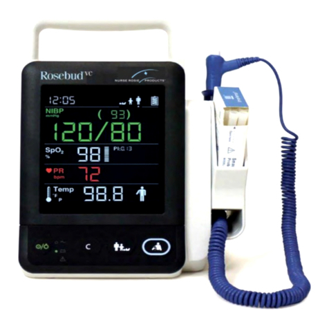
NURSE ROSIE Rosebud VC User manual

USER MANUAL
Vital Signs Monitor

Rosebud VC Page 2
WARNING
Only skilled/trained clinical professionals should operate this equipment.
It is important for the hospital, skilled nursing facility or organization that uses
this equipment to perform a reasonable service/maintenance plan. Neglecting
this may result in machine breakdown or personal injury.
Company Contact
Address 7320 Central Ave., Savannah, GA 31406
Website
nurserosie.com
E-mail info@nurserosie.com
Phone 800-841-1109
Fax 912-355-9191

Rosebud VC Page 3
Preface
ManualPurpose
This manual contains the instructions necessary to operate the product safely
and in accordance with its function and intended use. Observance of this
manual is a prerequisite for proper product performance and correct
operation and ensures patient and operator safety.
This manual is based on the maximum configuration and therefore some
contents may not apply to your product. If you have any questions, please
contact Nurse Rosie Products.
This manual is an integral part of the product. It should always be kept close
to the equipment so that it can be conveniently obtained when needed.
Intended Audience
This manual is intended for clinical professionals who are expected to have a
corresponding working knowledge of medical procedures, practices and
terminology as required for the monitoring of patients.
Illustrations
All illustrations in this manual serve as examples only. They may not
necessarily reflect the setup or data displayed on your equipment.
Manual Conventions
•
Italictext
is usedto quote the referenced chapters orsections.
•
[]is usedtoenclosescreentext.
•
→is used to indicate operational procedures.

Rosebud VC Page 4
Contents
Contents
Company Contact ............................................................................................................. 2
Preface
................................................................................................................................ 3
ManualPurpose
....................................................................................................................3
Intended Audience........................................................................................................... 3
Illustrations....................................................................................................................... 3
Manual Conventions........................................................................................................ 3
1
Safety
............................................................................................................................... 9
1.1
Safety Information
.................................................................................................... 9
1.1.1
Warnings
...............................................................................................................10
1.1.2
Cautions
................................................................................................................11
1.1.3
Notes
.................................................................................................................... 11
1.2EquipmentSymbols
.......................................................................................................13
2
The Basics
....................................................................................................................... 15
2.1
IntendedUse
.......................................................................................................... 15
2.2
AppliedParts
..........................................................................................................15
2.3
Mainunit................................................................................................................ 16
2.3.1
FrontView
............................................................................................................. 16
2.3.2
SideView
............................................................................................................... 17
2.3.3
RearView
..............................................................................................................18
2.3.4
BottomView
.......................................................................................................... 19
2.4
DisplayScreen
........................................................................................................ 20
3
Basic Operation
.............................................................................................................. 22
3.1
Installation
............................................................................................................. 22

Rosebud VC Page 5
3.1.1
UnpackingandChecking
......................................................................................... 22
3.1.2
EnvironmentalRequirements
................................................................................... 23
3.2
GeneralOperation
.................................................................................................. 23
3.2.1
ConnectiontoACPower
........................................................................................... 23
3.2.2
UsingaBattery
.......................................................................................................24
3.2.3
Connecting Accessories
........................................................................................... 24
3.3
TurningOn/Off Power
.............................................................................................. 25
3.3.1
TurningPowerOn
...................................................................................................25
3.3.2
Turning off the Monitor
........................................................................................... 26
3.4
Standby
.................................................................................................................26
3.4.1
EnteringStandbyMode
........................................................................................... 26
3.4.2
ExitingStandbyMode
............................................................................................. 27
3.5
UsingKeys
.............................................................................................................. 27
3.6
ParameterSetupMode
........................................................................................... 30
3.7
Maintenance Mode
................................................................................................. 30
3.7.1
SelectingNIBPUnitofMeasure
................................................................... 30
3.7.2
SelectingTempUnitofMeasure
.................................................................. 31
3.7.3
SettingSystemTime
................................................................................................31
3.7.4
ViewingSoftwareVersion
........................................................................................ 32
3.7.5
LoadingFactoryDefaultConfiguration
...................................................................... 32
3.7.6
Viewing OperatedTime
.......................................................................................... 33
3.7.7
AdjustingtheScreenBrightness
................................................................................ 34
3.7.8
DIAPCommunicationSetup
..................................................................................... 35
4.1 Overview
......................................................................................................................37
4.2 Safety
......................................................................................................................... 38

Rosebud VC Page 6
4.3
ApplyingtheSensor
................................................................................................. 39
4.4
SwitchingPulseToneOn/Off
..................................................................................... 39
4.5
MeasurementLimitations
........................................................................................ 41
5
MonitoringNIBP
............................................................................................................. 42
5.1
Overview
................................................................................................................42
5.2
Safety
.................................................................................................................... 42
5.3
MeasurementLimitations
........................................................................................ 43
5.4
Measuring NIBP
......................................................................................................43
5.4.1
Preparing the Patient
.............................................................................................. 43
5.4.2
PreparingtoMeasureNIBP
..................................................................................... 44
5.4.3
StartingandStoppingMeasurements
....................................................................... 45
5.4.4
Correcting theMeasurementwhenCuffisnotatHeart
Level
...................................... 45
5.5
UnderstandingtheNIBPNumerics
............................................................................ 45
5.6
CareandCleaningofReusableCuffs
.......................................................................... 46
5.6.1
Reusable Cuffs with Bladders
...................................................................... 46
5.6.2 Reusable Bladderless Cuffs
...................................................................................... 47
6
Monitoring Temp
............................................................................................................ 48
6.1
Overview
................................................................................................................48
6.2
SelectingMeasurementSite
..................................................................................... 49
6.3
Taking aTemperature
.............................................................................................. 50
6.3.1
Entering Predictive Mode and Monitor Mode
............................................................. 50
6.3.2
Taking aTemperatureinthe Predictive Mode
............................................................ 50
6.3.3
Taking aTemperature in Monitor Mode
.................................................................... 51
6.4
DisinfectingTemperatureProbe
................................................................................ 51
7
Battery
........................................................................................................................... 53
7.1
Overview
................................................................................................................53

Rosebud VC Page 7
7.2
ChargingaBattery
.................................................................................................. 53
7.3
ReplacingaBattery
................................................................................................. 54
7.4
BatteryGuidelines
................................................................................................... 54
7.5
Battery Maintenance
...............................................................................................55
7.5.1
ConditioningaBattery
............................................................................................ 55
7.5.2
CheckingaBattery
.................................................................................................. 55
7.6
RecyclingaBattery
.................................................................................................. 56
8 CareandMaintenance
.................................................................................................... 57
8.1
CleaningandDisinfection
......................................................................................... 57
8.1.1
Cleaning
............................................................................................................... 58
8.1.2
Disinfecting
........................................................................................................... 58
8.2
General Inspection
.................................................................................................. 59
8.3
MaintenanceandTestingSchedule
............................................................................ 59
8.4
Checking Monitor Information
.................................................................................. 60
8.5
Visual Inspection
..................................................................................................... 60
8.6
Power-onTest
.........................................................................................................60
8.7
BatteryCheck
......................................................................................................... 60
9Accessories
..................................................................................................................... 61
9.1
SpO2Accessories
.................................................................................................... 62
9.2
NIBP Accessories
.....................................................................................................63
9.3
TempAccessories
..................................................................................................... 64
9.4
Others
................................................................................................................... 64
A Product Specifications
................................................................................................... 65
A.1
Classifications
......................................................................................................... 65
A.2
Environmental Specifications
..................................................................................... 65

Rosebud VC Page 8
A.3
Power Supply Specifications
..................................................................................... 66
A.5.4
MonitorInterfaceSpecifications
................................................................. 67
A.6.3
NIBP
........................................................................................................... 69
A.6.4
Temp
.......................................................................................................... 70
C ErrorCodes
..................................................................................................................... 75
DSymbolsandAbbreviations
............................................................................................ 78
D.1
Symbols
.................................................................................................................78
D.2
Abbreviations
......................................................................................................... 79
A Product Specifications ....................................................................................................A-1
A.1 Classifications
......................................................................................................................................A-1
A.2 Environmental
Specifications........................................................................................................A-1
A.3 Power Supply
Specifications..........................................................................................................A-2
A.4 Physical Specifications
.....................................................................................................................A-2
A.5 Hardware Specifications
..................................................................................................................A-2
A.6 Measurement
Specifications..........................................................................................................A-3
B EMC................................................................................................................................... B-1
C Error Codes....................................................................................................................... C-1
D Symbols and Abbreviations ...........................................................................................D-1
D.1 Symbols
................................................................................................................................................ D-1
D.2 Abbreviations
..................................................................................................................................... D-2

Rosebud VC Page 9
1
Safety
1.1
Safety Information
WARNING
•
Indicates a potential hazard situation or unsafe practice that, if not avoided,
could resultindeathorseriousinjury.
CAUTION
•
Indicates a potential hazard or unsafe practice that, if not avoided, could
result in minor personal injury or product/property damage.
NOTE
•
Provides application tips or other useful information to ensure that you get
the
mostfrom your product.

Rosebud VC Page 10
1.1.1
Warnings
WARNING
•
The monitor does not provide any alarms. It only provides error codes and
is not intended for continuous monitoring. Keep the patient under close
surveillance when using this monitor.
•
This equipment is restricted to one patient at a time.
•
Before putting the system into operation, the operator must verify that the
equipment, connecting cables and accessories are in working order and
operating condition.
•
To avoid risk of electric shock, this equipment must only be connected to
a properly grounded power outlet. If a properly grounded power outlet is
not available, operate the monitor on battery power.
•
To avoid an explosion hazard, do not use the equipment in the presence
of oxygen–rich atmospheres, flammable anesthetics, or other flammable
agents (such as gasoline).
•
Do not open the equipment housings. All servicing or upgrades must be
carried out by Nurse Rosie Products trained and authorized personnel.
•
Do not come into contact with patients during defibrillation. Otherwise
serious injury or death could result.
•
Do not touch the equipment’s metal parts or connectors when in contact
with the patient; otherwise patient injury may result.
•
The physiological data and prompt information displayed on the
equipment is not intended to be directly used for diagnostic interpretation
and replace the competent judgment of a clinician.
•
To avoid inadvertent disconnection, route all cables to prevent a stumbling
hazard. Wrap and secure excess cabling to reduce risk of entanglement
by patients or personnel.
•
When disposing of the packaging material, be sure to observe the
applicable waste control regulations and keep it out of children’s reach.
•
When no battery is installed, make sure that the power supply is
continuous. A power interruption will result in data loss.
•
Put the equipment in a location where you can easily see the screen,
access the operating controls, and disconnect the equipment from AC
power.
•
The equipment uses a mains plug as isolation means to the mains power
supply.
•
Please do not position the equipment in a place difficult to access the
mains plug.
•
The equipment is not intended to be used within the magnetic resonance
(MR) environment.

Rosebud VC Page 11
1.1.2
Cautions
CAUTION
•
Only use parts and accessories specified in this manual.
•
Remove the battery before shipping the monitor or if it will not be used for
an extended period of time.
•
Carefully route patient cabling to reduce the possibility of patient
entanglement.
•
Disposable accessories are not designed to be reused. Reuse may cause
a risk of contamination and affect the measurement accuracy.
•
At the end of its service life, the equipment, and accessories, must be
disposed of in compliance with the guidelines regulating the disposal of
such products. If you have any questions concerning disposal of the
equipment, please contact Nurse Rosie Products.
•
Magnetic and electrical fields are capable of interfering with the proper
performance of the equipment. For this reason, make sure that all external
devices operated in the vicinity of the equipment comply with the relevant
EMC requirements. Mobile phones and X-ray equipment are a possible
source of interference as they may emit higher levels of electromagnetic
radiation.
•
Before connecting the equipment to the power line, check that the voltage
and frequency ratings of the power line are compatible those indicated on
the equipment’s label or in this manual.
•
Always install or carry the equipment properly to avoid damage caused by
a drop, impact, strong vibration or other mechanical force.
•
If you spill liquid on the equipment or accessories, contact Nurse Rosie
Products or your service personnel.
1.1.3
Notes
NOTE
•
The equipment is intended to be used for immediate, supervised, point of
care monitoring, and not for continuous monitoring. The equipment cannot
be configured to obtain periodic physiological measurements at set
intervals; rather, it is used by a healthcare provider to obtain an immediate
measurement.
•
Keep this manual in the vicinity of the equipment so that it can be easily
located when needed.
•
The software was developed in compliance with IEC60601-1- 4. The
possibility of hazards arising from software errors is minimized.
•
This manual describes all the equipment features and options. Your
equipment may not have all of them.
•
Only connect the specified device into an RS-232 connector.

Rosebud VC Page 12
•
During normal use, the operator is expected to face the front of the
equipment

Rosebud VC Page 13
1.2 EquipmentSymbols
Some symbols may not appear on your equipment.
Caution
Neonate
ON/OFFforapartof
equipment
Pediatric
Clear key
Adult
Alternating current
Equipotentiality
Battery indicator
Input/Output
DEFIBRILLATION
–
PROOF
TYPECFAPPLIEDPART
DATE OF MANUFACTURE
NIBPStart/Stopkey
MANUFACTURER
Protection against fluid
ingress
Insertion Direction
Serialnumber
Alarminhibit
Refertoinstructionmanual/
booklet
Atmosphericpressure
limitation
Temperature limit
Humidity limitation
Interference may occur in the
vicinity of equipment marked
with this symbol
CATALOGUE NUMBER
AUTHORIZED REPRESENTATIVE IN THE EUROPEAN COMMUNITY
The product bears CE mark indicating its conformity with the provisions
ofthe Council Directive 93/42/EEC concerning medicaldevices andfulfills
the essential requirements of Annex I of this directive.

Rosebud VC Page 14
The followingdefinitionofthe WEEElabelapplies to EU member states
only.
Thissymbolindicatesthatthisproductshouldnotbetreatedas
householdwaste.Byensuringthatthisproductisdisposedofcorrectly,
youwillhelppreventbringingpotentialnegativeconsequencestothe
environmentandhumanhealth.Formoredetailedinformationwith
regardtoreturningandrecyclingthisproduct,pleaseconsultthe
distributorfromwhomyoupurchasedit.
* For system products, this label may be attached to the main unit only.
The presence of thislabel indicatesthe machine was certifiedby ETL with
the statement:
Conforms to AAMI Std. ES 60601-1, IEC Std. 60601-1-6, IEC Std.
80601-2-30, ISOStd. 80601-2-56, ISO Std. 80601-2-61.
Certified to CSA Std. C22.2 NO. 60601-1, NO. 60601-1-6, NO. 80601-2-30,
NO. 80601-2-56, NO. 80601-2-61.

Rosebud VC Page 15
2
The Basics
2.1
Intended Use
The monitor is intended for spot-check monitoring physiologic parameters,
including Pulse Oximetry (SpO2), Pulse Rate (PR), Non Invasive Blood
Pressure (NIBP) and Temperature (TEMP), on adult, pediatric, and neonatal
patients in healthcare facilities by physicians or appropriate medical staff
under the direction of physicians.
This monitor is intended for use only by clinical professionals or under their
guidance. It must only be used by persons who have received adequate
training in its use.
2.2
AppliedParts
The applied parts of the monitor are SpO2 sensor and cable, NIBP tubing
and cuff, and Temp probes and cable.

Rosebud VC Page 16
2.3
Mainunit
2.3.1
FrontView
10
9
1
8
2
3
1.
Display screen
2.
AC power indicator
•
On: indicates that the monitor is connected to the AC power.
•
Off: indicates that the monitor is not connected to the AC power.
3.
PowerON/OFFswitch
•
Press this key to turn the monitor on.
•
If no parameter isbeing measured, press this key to enter Standby mode.
•
Whenthemonitorison,pressandholdthiskeyformorethan2secondstoturn
themonitoroff.
•
Anindicatorisbuiltintothisswitch.Itturnsgreenwhenthemonitorison,turns
yellowwhenthemonitorentersStandbymode,andturnsoffwhenthemonitor
is
off.
45 6 7

Rosebud VC Page 17
4.
Battery indicator
•
On: indicates that the battery is installed and the AC power is connected.
•
Off: indicates that no battery is installed when AC power is connected, or
indicates that the battery is installed, but no AC power is connected when
the monitor is powered off.
•
Flashing: indicates that the monitor is powered by battery.
5.
Clear key
•
InMeasurement mode, press this key to clear currently displayed
measurements and errorcode.
•
In Measurement mode, press and hold this key for more than 2 seconds to
accesstheParameterSetupmode.
•
When the monitor is starting up and a beep is heard, press and hold this
key
immediately (within 10 seconds after the beep) to access the
Maintenance
mode.
6.
Patient Categorykey
•
In Measurement mode, press this key to toggle among adult, pediatric and
neonate.
7.
NIBPStart/Stopkey
•
InMeasurement mode,press this keytostart or stop an NIBP
measurement.
8.
Probecoverpack holder
9.
Temperature probe well
10.
Handle
2.3.2
SideView
1.
ConnectorforSpO2 cable
2.
ConnectorforNIBPcuff
1
2

Rosebud VC Page 18
2.3.3
RearView
1
2
4
3
5
6
1.
Handle
2.
Temperature probe well
3.
Connectorfortemperatureprobe
4.
Input/Output connector (RS-232 connector)
•
This connectorcan be usedforsoftwareupgradeand DIAP(Datascope
ImprovedASCIIProtocol)communication.
5.
AC power input
6.
Equipotential grounding terminal
NOTE
•
When using the equipment with other devices, their equipotential
grounding terminals should be connected together to eliminate a possible
difference in ground potential.

Rosebud VC Page 19
2.3.4
Bottom View
1
2
1.
Battery compartment door
2.
Quickreleasemountlatchpoint

Rosebud VC Page 20
2.4
DisplayScreen
1 2 3 4
8
5
6 9
10
11
12
13 14
15
18 21
19 20
1.
Patient category (Adult, Pediatric, Neonate)
2.
Errorcode
Referto
CErrorCodes
foradditional information.
3.
Systemtime
4.
Charge level indicator
5.
NIBP label
6.
NIBPunitofmeasure
7.
Systolic pressure
8.
Cuffpressure:displayedduringNIBPmeasurement.
9.
NIBPcuffindicator
Whenerrorssuchasairleak,incorrectairpressure,weaksignal,overpressure,
incorrect cuff type, or excessive patient motion etc. occur, the cuff indicator
displays.
10.
Diastolic pressure
11 SpO2 label
12.
SpO2 unitof measure
13.
SpO2 value
14.
SpO2sensorindicator:
16
17
7
Other manuals for Rosebud VC
1
Table of contents
Other NURSE ROSIE Medical Equipment manuals