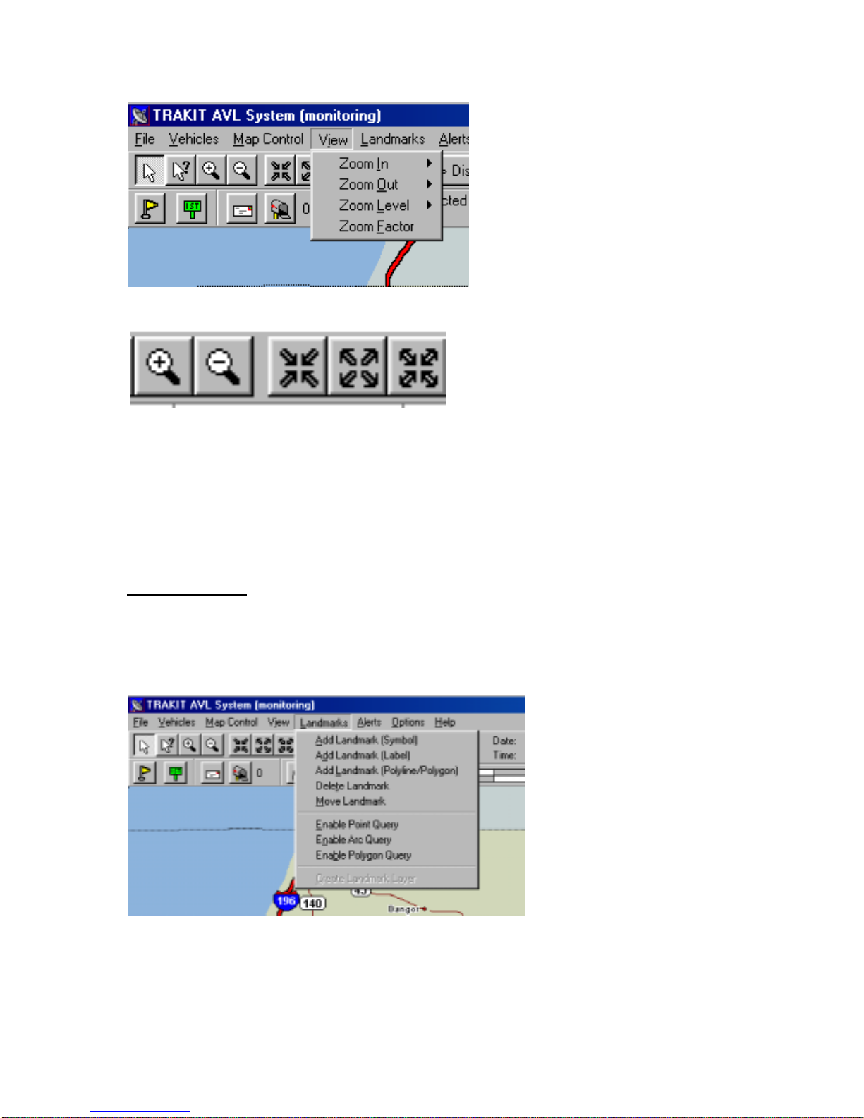
IDA TRAKIT USA User manual

CORPORATION
TRAKIT USA
INSTRUCTION
MANUAL

2
Welcometo training on IDA Corporation’s TRAKIT GPS AVL Fleet Management
System. This training is focused on basic operation of the TRAKIT system using a radio
communications link.. You will get familiar with the fundamentals, know where to go if
you have questions and be exposed to most of the features and functions of the system.
Areas that will be covered are
Overview
Installation descripton (not installation training)
System Configuration
Software and maps
Vehicles
Operation

3
OVERVIEW
Elements of the system
Vehicle Equipment
Equipment installed in the vehicle will include (at least) the TRAKIT vehicle device
connected to the mobile radio. The TRAKIT vehicle device includes the GPS receiver,
communications modem and a data buffer. A GPS antenna connects to the TRAKIT and
is installed to have a clear view of the sky.
The radio has its own antenna and is used to send locations from the vehicle through the
radio communications network to the base station.
Dispatch Base
At the base station the data is received by the base radio and sent to the TRAKIT base
device. A computer with TRAKIT software connects to the TRAKIT base device to
accept the data and process it. The data is used for display of vehicle icons over a digital
Data Files
Base Dispatch
Radio
VEHICLE
Vehicle
TRAKIT
Radio
Vehicle Icon
(Software)
TRAKIT Vehicle Supervisor TRAKIT Vehicle Terminal
GPS Satellite
900 MHz
800 MHz
450 MHz
150 MHz
220 MHz
DISPATCH BASE
Printer
Screen Output
Vehicle Icon
Computer
Data Buffer
TRAKIT GPS AVL
Fleet Management System
COMMUNICATION LINK
SYSTEM
CELLULAR
TOWER RADIO SATELLITE
ORBCOMM
Cellular
GPS Antenna
LEO
(Cellular/LEO E-mail)
Land line Phone
- or - - or -
(OPTIONAL)
- or -
Monitor
Play Back
Event Alerts
Printed Maps
Preventive Maintenance -
Reports
Graphs
Schedules
(LEO)
12V Power
Supply
TRAKIT
Base

4
map on the screen or for creating files to be archived or used for generation of a variety
of operation and management reports.
Installation
Vehicle
When the TRAKIT vehicle device is attached to the radio in the vehicle it is assigned an
identifying number. This number is made up of a 3 digit GROUP NUMBER and a 3
digit ID NUMBER. This is how the system identifies the individual vehicles. This
number is recorded in the software module along with other information about that
particular vehicle
Dispatch Base
At the dispatch base station a TRAKIT base device is connected between the base radio
and the computer. The TRAKIT base software is installed in the computer.

5
Software and Map
Map Functions
The map menus and buttons allow you to easily choose the function you want to perform
or navigate around on the map. Click on these menu options to see the sub-menus.
File Vehicles Map Control View Landmarks Alerts Options Help
Navigation
Point and center
The cursor is used to move the map. When you click the left mouse button (left-click)
the map will readjust so that the point that you clicked is positioned in the center of the
screen. This is a good way to pan the map either horizontally or vertically.
Zoom
There are several ways to have the map zoom-in or zoom-out.
From the menu bar you can click on VIEW. This will bring up a menu of zoom options.
View

6
Or, you can select one of the zoom speed buttons in the row directly under the menu bar
Left-click on the magnifying glass buttons to zoom in (+) or zoom out (-) and then place
the cursor at some position on the map. The map will zoom and at the same time center
on the position where you put your cursor. The next two buttons do not require placing
the cursor on the map. The screen will stay in position and just zoom. Left-click on the
last button and you will zoom in to the smallest level. Left-clicking this button again and
you return to the level you came from.
Landmarks
Landmarks are icons you can place anywhere on the map to use as reference points or to
provide you with additional information about a certain point on the map. There are
numerous icons to choose from and you can manage them to represent anything that
serves your purpose.
Select LANDMARKS from the menu bar. This will bring up a menu for creating and
maintaining the landmarks. When you select ADD A LANDMARK SYMBOL you will
go to the LANDMARK SYMBOL box

7
Landmarks
Add Landmark Symbol
The LANDMARK LAYER is a file that is created. If a landmark layer has not been
created for you see CREATE LANDMARK LAYERS in these instructions. You can
have numerous landmark layer files open at any one time. You may want certain
landmark layers visible at different times. For that you would manage which landmark
layers were visible or invisible. To do this see MAP PROPERTIES in these instructions.
After selecting the landmark layer file you can choose the landmark Symbol you want to
use. There are many to choose from. If the Symbol shows in black you can change the
color. If the Symbol shows in a color already you cannot change the color. You can set
the Size by points. You may want to experiment with Sizes to become familiar with how
.big or small the numeric value will make the landmark. By checking the Scale to map
box the landmark will dynamically change in size to match the zoom level. If you want
the landmark to stay the same size no matter what the zoom level, leave this box
unchecked. You can create multiple landmarks on the map at one time if you check the
box Make multiple copies of the Symbol.
Position the cursor on the map where you want to place the landmark. Left-click once to
place the landmark.

8
Labels
Labels are text strings that you can put on one or many positions on the map. They can
be used to label a landmark or to apply custom annotation to the map. To create a label
left-click on ADD LANDMARK LABEL from the LANDMARK menu. The
LANDMARK LABEL box will appear.
Landmarks
Add Landmark Label

9
The landmark label is assigned to a landmark layer just like a landmark symbol. In the
Label box, type the text label that you want to put onto the map. You can rotate the label
to present the label in any attitude desired on the map. The Size can be set. A selection
can be made from a variety of colors. By checking the Make multiple copies of this
Label box multiple labels can be applied to the map at one time. The Scale to map box
will make the label change in size with the change in zoom level. Not changing this box
will cause the label to remain the same size no matter what the change in zoom level.

10
Point & Click Data Feature
The TRAKIT system has a unique feature called Point & Click Data Feature. This
feature provides for a database to be associated with map landmarks. When the landmark
layer is created you can set up a set of file fields that, when landmarks are put onto the
map the operator can enter data in each of the fields. You can have several landmark
layers active at the same time, each with a unique set of data fields. One could have
names and addresses of customers. Others could have numbers of tanks with tank
capacities. Others could have special instructions that when a driver approaches the
reference point the dispatcher can advise the driver of the instructions. You can also
control when each landmark is displayed or not displayed on the map.
When the Point & Click data feature is enabled (see Create Landmark Layers), and you
go to place a landmark on the map you will see the ITEM INFORMATION dialog box
for you to enter data.

11
To close the ITEM INFORMATION box left-click on OK. The landmark will remain on
the map at the position where you put your cursor.
To see the data that is associated with each landmark left-click on ENABLE POINT
QUERY from the LANDMARK menu.
Landmarks
Enable Point Query
This will change the cursor to an arrow with a + sign. Left-click on the landmark. This
will bring up the ITEM INFORMATION box with the data associated with that
landmark. While the box is on the screen the data in the fields can be changed. This
means that these databases can be maintained on-screen.
The databases used with the Point & Click Data Feature are .db files. These files are
commonly maintained by Microsoft Access, Paradox, dBase and many other database
manager-type utilities. The files can be manipulated and updated outside of TRAKIT.
This means that updates from outside files like accounts receivable, sales or notation files
could be easily accessible by the Point & Click Data Feature.
Create Landmark Layers
Each landmark symbol and landmark label must be attached to a landmark layer. You
may want to spend some time analyzing how management of landmark layers will benefit
your application. You can turn layers on or off depending on the presentation you wish
to have on the screen at any given time. Each landmark layer can be associated with a
custom database that provides the Point & Click Data feature. For this feature you
determine the fields of data in the database. These fields can then be maintained on-
screen by using the Enable Point Query function.

12
To create a Landmark Layer go to LANDMARKS, CREATE LANDMARK LAYER
Landmarks
Create Landmark Layer
Create fields of the file by left-clicking on Add Field. In the Field Information box the
Name will indicate the next field number available. You can change this to any field
name you wish. You can indicate the Type and size (Width) of the field. Field Indexed
is reserved for advanced users. By clicking on Create you will have created the landmark
layer.
Visible control
You can control whether or not the landmark will be displayed on the map. When setting
up the Point & Click Database Data structure include a field called “visible”. Indicate the
field Type as “logical”. This field acts like a toggle switch by turning on or off (True or
False) the display of this landmark.
Map Properties
You can manage landmark files in the Map Properties box. Get there by MAP
CONTROL, MAP PROPERTIES.

13
Map Control
Map Properties
Double-clicking on a landmark layer brings up the Layer Properties box. Under Layer
Controls you can indicate in the Layer Visible box if you want the layer to be used on the
map. Other parameters in the box are reserved for advanced users only.

14

15
Additional Map Views
Besides the main full-screen map view up to two additional views can be displayed on
the screen. To show the additional views left-click on MAP CONTROL on the menu
bar, then select either or both of MAP VIEW 1 and MAP VIEW 2.
Map Control
Map View 1 (or) Map View 2
Each of the map views can have independent zoom levels. Each of the views can be
programmed to follow a vehicle. This is a good way to follow several vehicles at street-
level zoom or to monitor a vehicle at street-level and wide-area zoom levels at the same
time.

16
Vehicle Info List
The Vehicle Info List is a box that is displayed on the screen showing the text address
and other information about each position received from each vehicle. The box can be
sized and placed anywhere on the screen. Initiate the Vehicle Info List by selecting
SHOW VEHILCE INFO LIST from the VEHICLES menu
Vehicles
Show Vehicle Info List
Alert Zones
You can set up zones on the map to detect if vehicles enter or leave specified areas on the
map. To Work with zones select ALERTS from the menu bar, then ZONE. To make a
new alert zone select NEW.
Alerts
Zone
New

17
Select a zone type. You can set the zone to apply to all vehicles, a single vehicle or to
detect the movement of a vehicle. If for only one vehicle select that vehicle from the
vehicle identification box. The Zone activation threshold is the number of meters that the
vehicle will enter or leave the zone before the zone alert will be triggered.
Position and size the zone by clicking and dragging across the map. Left-click to confirm
position and size of the zone. If the zone does not show on the map, check the ALERTS,
VIEW, OPTIONS menu selection.

18
Alerts
View
Options
Make sure the Display zones box is checked. This is also where you can select the color
of the zone lines.

19
Map Control- Display Options
Map Control
Display Options
Use this box to change the display of DMS (Degrees, Minutes, Seconds) and metric
values as well as tell the system to indicate the direction of travel of the vehicle icon by
pointing the icon in that direction.
Grid Lines, Grid Tics
You may want to set up additional reference points to make the job of dispatching easier.
Grid Lines and Grid Tics can help. Select these options from the MAP CONTROL
menu.
Map Control
Grid Lines (or) Grid Tics

20
Grid Lines
Grid Tics
Drawing Tool
The TRAKIT map includes a drawing tool for placing lines and shapes on the map.
From the MAP CONROL menu select the ADD LANDMARK
(POLYLINE/POLYGON).
Map Control
Add Landmark (Polyline/Polygon)
Table of contents