ADS-DSR1-HD02-AR-IG-EN maestro.idatalink.com
HARLEYDAVIDSON ELECTRA GLIDE 20142020
Automotive Data Solutions Inc. © 2020 3
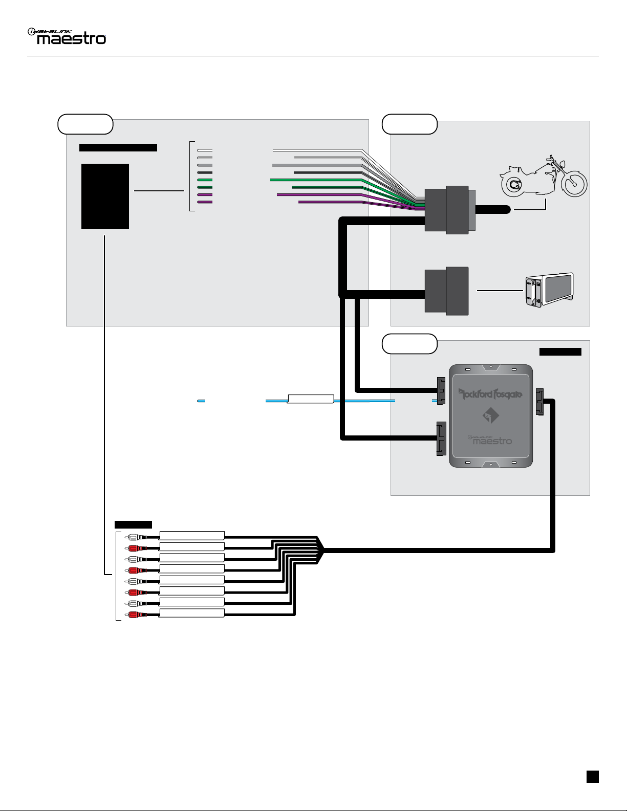
INSTALLATION INSTRUCTIONS
STEP 1
• Remove the factory radio and plug the HD2 T-Harness in
line with the radio plug.
STEP 2
• Connect the speaker wires from the HD2 T-harness to the
aftermarket amplifier.
Note 1:
If you are running your own speaker wires from the
amplifier to the speakers, this step is not necessary.
• Plug the RCA cables in the aftermarket amplifier.
• Connect the Blue/White AMP TURN ON wire to secondary
amplifier (only if equipped).
STEP 3
• Connect all the harnesses to the DSR1 module.
• Connect the Blue/White AMP TURN ON wire to aftermarket
amplifier.
STEP 4
Program the OEM radio to “amplified mode”.
• Turn ignition ON.
• Within 5 seconds, pull the clutch handle ON-OFF 5 times.
• Wait. The horn will honk one time to confirm you are in
programming mode (the LED should blink slow green).
• Within 10 seconds, set the turn signal LEFT to add the
ampliflier (the horn will honk one time to confirm that you
chose an option).
• Wait. The radio should reboot one time, and horn will honk:
2 times: Amplified mode (the LED should also blink 2x
GREEN).
5 times: Failed to program (the LED will blink red).
iMPORTANT: Once programming is SUCCESSFUL, the DSR1
is locked to this particular motorcycle and radio and will
not be able to be used with or flashed for any other vehicle
until the factory radio is returned to the non-amplified mode
before the DSR1 is removed.
If you need to return the radio to its factory nonamplified
mode, do this programming procedure and select the
RIGHT turn signal instead. It will honk 3 times to confirm
the selection.
For technical assistance :
Call : 1-866-427-2999
Visit us at : maestro.idatalink.com/support and
www.12voltdata.com/forum/
1