Ideal Heating QAA55 User manual

When replacing any part on this appliance, use only spare parts that you can be assured conform to the safety and performance
specication that we require. Do not use reconditioned or copy parts that have not been clearly authorised by Ideal Heating.
For the very latest copy of literature for specication and maintenance practices visit our website idealheating.com
where you can download the relevant information in PDF format.
QAA55 ROOM
THERMOSTAT KIT
INSTRUCTIONS
HEATING
April 2021
UIN 226216 A02
IMAX XTRA 2
80 120 160 200 240 280
80P 120P 160P 200P 240P

2IMAX XTRA 2 - QAA55 Room Thermostat Kit Instructions
INSTRUCTIONS
1.1 Introduction........................................................................ 2
1.2 QAA55 Room Thermostat Kit Parts...................................2
1.3 Fitting the QAA55 Room Thermostat ................................3
1.4 Connecting the QAA55 Room Thermostat - 1................... 4
1.5 Connecting the QAA55 Room Thermostat - 2................... 5
1.6 Connecting the QAA55 Room Thermostat - 3................... 6
CONTENTS
1.1 INTRODUCTION
This allows temperature setting of individual heating zones, up to a maximum of three zones using the QAA55 Kit.
Please refer to the installation and servicing manual for guidance on adding the additional heat zones.
The kits consist of the following parts:
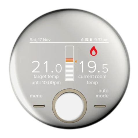
1. QAA Room Thermostat – UIN 533901589
Shown in Fig. 1.
2. Room Sensors Connector Kit - Shown in Fig. 2.
Fig. 1 Fig. 2
1.2 QAA55 ROOM THERMOSTAT KIT PARTS
I10_CN_A I10_CN_B I10_CN_C

3
IMAX XTRA 2 - QAA55 Room Thermostat Kit Instructions
INSTRUCTIONS
1.3 FITTING THE QAA55 ROOM THERMOSTAT
The room thermostat should be installed approximately
1.5m high on a wall located in the space to be heated.
thermostat cover as shown in Fig.3
Thermostat back plate to the wall, as shown in Fig.4.
Fig. 4
Fig. 3
Feed the 2-wire cable through the rear, or the top, of the
back plate and connect the wiring as follows:
1. Connect the red wire to pin 1 of connector
(CL+ BSB Data)
2. Connect the black wire to pin 2 of connector
(CL- BSB Ground)
These connections are shown Fig.5.
Fig. 5
Place the cover back onto the back plate, as shown in Fig.6.
Fig. 6
Rear
Top
For rear entry, route
the cable through
the rear prior to

4IMAX XTRA 2 - QAA55 Room Thermostat Kit Instructions
INSTRUCTIONS
Refer to the boiler manual for cable routing into the boiler.
Secure the cables with existing cable retention clamps or
cable tie slots that are on the boiler main control panel.
Ensure that isolation is maintained relative to 240V wiring.
manual.
1. Connect the CL+ BSB Data red wire to pin 1 of connector
2. Connect the CL- BSB Ground black wire to pin 2 of
These connections are shown Fig.7.
Insert connector 10_CN_A into Installer connector 10A,
as shown in Fig.8.
1.4 CONNECTING THE QAA55 ROOM THERMOSTAT _1
Fig. 7
Fig. 8
QAA55 -
QAA55 +
12 11 10 9
6a 6b 5 4 3 2 1
I10_CN_A

5
IMAX XTRA 2 - QAA55 Room Thermostat Kit Instructions
INSTRUCTIONS
1.5 CONNECTING THE QAA55 ROOM THERMOSTAT _ 2
Refer to the boiler manual for cable routing into the boiler.
Secure the cables with existing cable retention clamps or
cable tie slots that are on the boiler main control panel.
Ensure that isolation is maintained relative to 240V wiring.
manual.
If the QAA55 Room Thermostat is required to run heating
1. Connect the CL+ BSB Data red wire to pin 1 of
2. Connect the CL- BSB Ground black wire to pin 2 of
These connections are shown Fig.9.
as shown in Fig.10.
Fig. 9
Fig. 10
QAA55 -
QAA55 +
12 11 10 9
6a 6b 5 4 3 2 1
I10_CN_B

6IMAX XTRA 2 - QAA55 Room Thermostat Kit Instructions
INSTRUCTIONS
1.6 CONNECTING THE QAA55 ROOM THERMOSTAT _ 3
Refer to the boiler manual for cable routing into the boiler.
Secure the cables with existing cable retention clamps or
cable tie slots that are on the boiler main control panel.
Ensure that isolation is maintained relative to 240V wiring.
manual.
If the QAA55 Room Thermostat is required to run heating
1. Connect the CL+ BSB Data red wire to pin 1 of
2. Connect the CL- BSB Ground black wire to pin 2 of
These connections are shown Fig.11.
as shown in Fig.12.
Fig. 11
Fig. 12
QAA55 -
QAA55 +
12 11 10 9
6a 6b 5 4 3 2 1
I10_CN_C

7
IMAX XTRA 2 - QAA55 Room Thermostat Kit Instructions

WEEE DIRECTIVE 2012/19/EC
Waste Electrical and Electronic
Equipment Directive
• At the end of the product life, dispose of the
packaging and product in a corresponding
recycle centre.
• Do not dispose of the unit with the usual
domestic refuse.
• Do not burn the product
• Remove the batteries
• Dispose of the batteries according to the local
statutory requirements and not with the usual
domestic refuse.
At Ideal Heating we take our environmental impact seriously, therefore when installing any Ideal Heating product please make sure to dispose of any
previous appliance in an environmentally conscious manner. Households can contact their local authority to find out how.
See https://www.gov.uk/managing-your-waste-an-overview for guidance on how to efficiently recycle your business waste.
Technical Training
Our Expert Academy offer a range of training options designed and delivered by our experts in heating.
For details please contact:
expert-academy.co.uk
Ideal is a trademark of Ideal Boilers.
Registered Office
Ideal Boilers Ltd., National Avenue, Hull, East Yorkshire, HU5 4JB
Tel 01482 492251 Fax 01482 448858
Registration No. London 322 137
Ideal Commercial Technical Helpline: 01482 498376
Ideal Parts: 01482 498665
idealheating.com
Manufactured under
an ISO 9001
registered quality
management system
FM 59915
Ideal Boilers Ltd., pursues a policy of continuing improvement in the design and performance of its products.
The right is therefore reserved to vary specification without notice.
HEATING
Other Ideal Heating Thermostat manuals