IDEAL INDUSTRIES 61-361 User manual

IDEAL INDUSTRIES, INC.
TECHNICAL MANUAL
MODEL: 61-361
MODEL: 61-361 True RMS {Modified 2002}
The Service Information provides the following information:
•Precautions and safety information
• Specifications
• Performance test procedure
• Calibration and calibration adjustment procedure
• Basic maintenance (replacing the battery and fuses)
Form number: TM61361
Revision: 3. Date: Nov 2002
Form number TM61361 Rev 3 November 2002

TABLE OF CONTENTS
Title Page
Introduction 1
Precautions and Safety Information 1
Safety Information 1
Specifications 2
General Specification 61-361 2
Voltage Specifications 61-361 2
Current Specifications 61-361 2
Resistance Specifications 61-361 2
Diode / Continuity Specifications 61-361 2
Capacitance Specifications 61-361 2
Phase Measurement 61-361 2
General Specification 61-361 True RMS 3
Voltage Specifications 61-361 True RMS 3
Current Specifications 61-361 True RMS 3
Resistance Specifications 61-361 True RMS 3
Diode / Continuity Specifications 61-361 True RMS 3
Capacitance Specifications 61-361 True RMS 3
Phase Measurement 61-361 True RMS 3
Performance Verification 3
Table 1 Verification 61-361 4
Table 2 Verification 61-361 True RMS 5
Calibration 6
Replacing the Battery 6
Replacing Fuses 7
Form number TM61361 Rev 3 November 2002

Page 1
Introduction
Warning
To avoid shock or injury, do not perform the verification tests or calibration
procedures described in this manual unless you are qualified to do so.
The information provided in this document is for the use of qualified personnel
only.
Caution
The 61-361 contains parts that can be damaged by static discharge.
Follow the standard practices for handling static sensitive devices.
For additional information about IDEAL INDUSTRIES, INC. and its products,
and services, visit IDEAL INDUSTRIES, INC. web site at:
www.idealindustries.com
SAFETY
Review the following safety precautions to avoid injury and prevent damage to this product or any
products connected to it. To avoid potential hazards, use the product only as specified.
CAUTION.
These statements identify conditions or practices that could result in damage to the equipment or other
property.
WARNING.
These statements identify conditions or practices that could result in personal injury or loss of life.
Specific precautions
Use proper Fuse. To avoid fire hazard, use only the fuse type and rating specified for this product.
Do not operate without covers. To avoid personal injury, do not apply any voltage or current to the
product without the covers in place.
Electric overload. Never apply a voltage to a connector on the product that is outside the range specified
for that connector.
Avoid electric shock. To avoid injury or loss of life, do not connect or disconnect probes or test leads
while they are connected to a voltage source.
Do not operate in wet/damp conditions. To avoid electric shock, do not operate this product in wet or
damp conditions.
Form number TM61361 Rev 3 November 2002

Page 2
General specifications
Model 61-361 and Model 61-361 True RMS {Modified}
Characteristics Description
Display 3 ½ Digit LCD display
Display Count 2000 count, maximum reading 1999
Overrange Indication “OL” displayed
Sampling Rate 3 time/second
Operating Environment:
Relative Humidity
0°C to 50°C (32°F to 122°F) 70%RH
Storage Environment: -20°C to 60°C (-4°F to 140°F) at <70 relative humidity
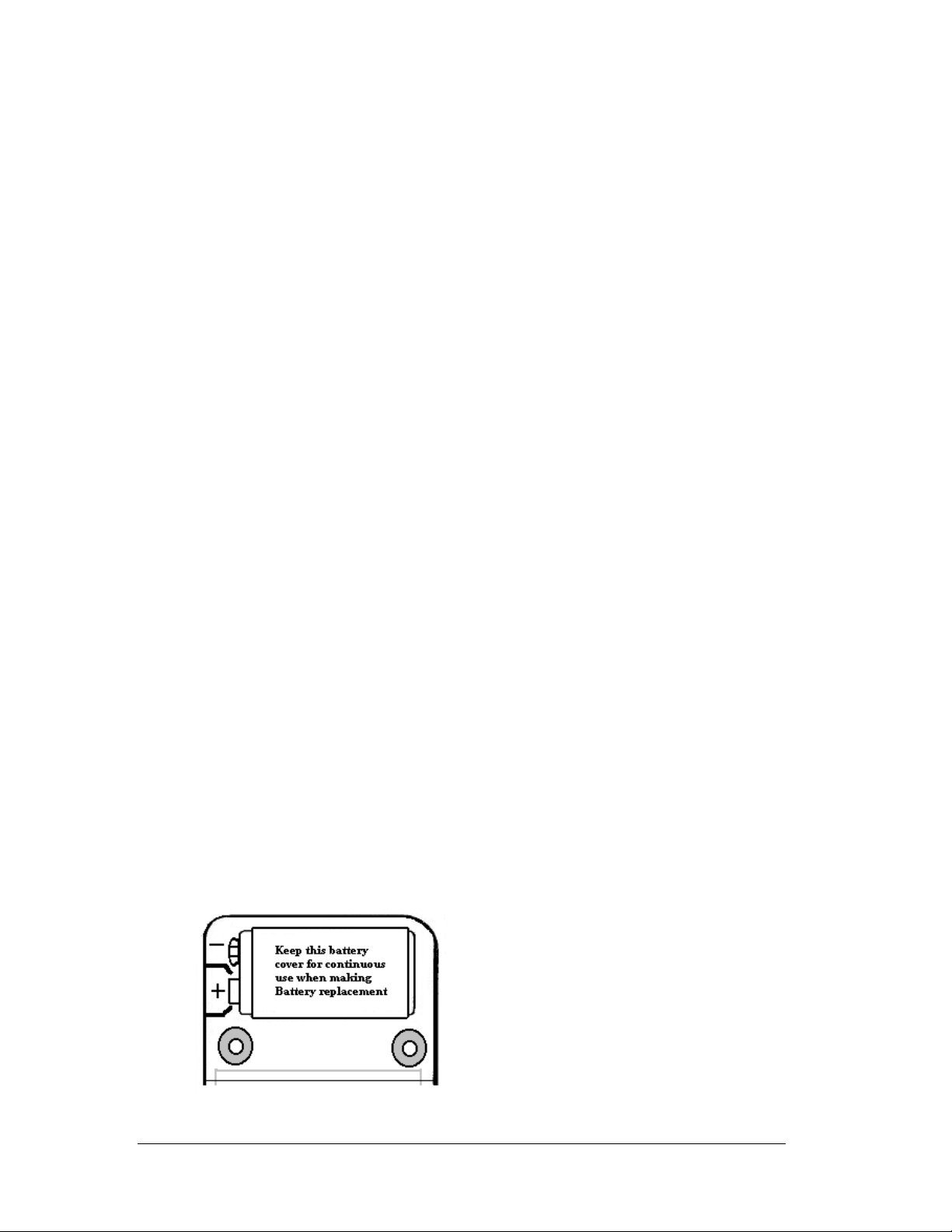
Power source: 9V Battery (NEDA 1604)
Battery Live: 200 hours typical (alkaline)
Low Battery Indicator: symbol indicates low battery voltage
Auto Power Off mode Approximately 25 minutes
A protection Fuse 2A/600V fast acting fuse Type LA-3893 and
0.1A/250V fast acting fuse, Type LA-3898
Dimensions 4.0” H X 7.5” W X 2.5” D
Weight: Approximately 18.0 oz. including battery
Safety UL1244, and Designed to comply with IEC 1010-1 Cat III
RANGES and ACCURACY SPECIFICATION
61-361
Function Setting Ranges Accuracy
AC Voltage 200mV/200/600V, 50Hz to 500Hz 2.0% ± 4 digits
DC Voltage 200mV/2V/20V/200V/600.0V 1.2% ± 1 digits
AC Current 2A, 50Hz to 500Hz 3.0% ± 4 digits
DC Current 2A 3.0% ± 4 digits
RST(Phase) 50Hz to 500Hz / 80V to 450V Not Specified 1
Hz 10Hz to 100KHz 2.0% ± 3 digits
Resistance 200.0Ω/2.000KΩ/20.00KΩ/200.0KΩ
20.00MΩ
200.0MΩ
1.5% ± 4 digits
2.5% ± 4 digits
5.0% ± 20 digits
Continuity Beep < 150ΩNot Specified
Capacitance 20µ/200µ/2m/20m 4.0% ±4 digits
Diode Check DCV 2V @ 1.0 mA ± 0.6 mA Not Specified
AC Converter: Average responding, RMS Calibrated to Sine Wave
Overload Protection: 200mV range, 500VDC or 350V RMS for no more that 15 sec.
2V to 600V range, AC or DC Voltage: 600V DC or AC RMS.
Resistance, Diode, Continuity: 500V DC or AC RMS.
MFD input, 0.1A / 250V fast acting fuse.
2A (R/L1) input, 2A / 600V fast acting fuse.
R/L2 input, not fused.
1 RST R S T will be displayed in the upper left corner if all three supply lines are powered
If meter indicates an “OK” message in display phase rotation is Clockwise
If meter indicates An “ER” message in display phase rotation is Counter Clockwise
Form number TM61361 Rev 3 November 2002

Page 3
RANGES and ACCURACY SPECIFICATION
61-361 True RMS {modified}
Function Setting Ranges Accuracy
AC Voltage 200mV/2000mV/200V/600V,
50Hz to 500Hz
2.0% ± 4 digits
DC Voltage 200mV/2000mV/20V/200V/600V 0.5% ± 2 digits
AC Current 2A, 50Hz to 500Hz 3.0% ± 4 digits
DC Current 2A 2.5% ± 4 digits
RST(Phase) 50Hz to 500Hz / 80V to 500V Not Specified 1
Hz 10Hz to 100KHz 2.0% ± 3 digits
Resistance 200.0Ω/2.000KΩ/20.00KΩ/200.0KΩ
20.00MΩ
200.0MΩ
1.0% ± 4 digits
2.0% ± 4 digits
5.0% ± 10 digits
Continuity beep < 30ΩNot Specified
Capacitance 200µF/2KµF/20KµF 4.0% ±10 Digits
Diode Check DCV 2V @ 1.0 mA ± 0.6 mA Not Specified
AC Converter: True RMS, RMS Calibrated to Sine Wave
Overload Protection: 200mV range, 500VDC or 350V RMS for no more that 15 sec.
2V to 600V range, AC or DC Voltage: 600V DC or AC RMS.
Resistance, Diode, Continuity: 500V DC or AC RMS.
MFD input, 0.1A / 250V fast acting fuse.
2A (R/L1) input, 2A / 600V fast acting fuse.
R/L2 input, not fused.
1 RST R S T will be displayed in the upper left corner if all three supply lines are powered
If meter indicates an “OK” message in display phase rotation is Clockwise
If meter indicates An “ER” message in display phase rotation is Counter Clockwise
PERFORMANCE VERIFICAITONS
Perform the following analysis, if the meter conforms to the limits listed in Table 1 the meter is functioning
correctly. If the meter does not conform to any of the listed limits the calibration procedure must be
performed.
Performance Verification Preparation
1. Turn on the Calibrator, allow calibrator to warm up. Temperature Stabilization
should be reached after 30 minutes.
2. Remove battery cover and using a calibrated meter to ensure the battery measures a minimum of 7.5V
DC. If the battery measures under 7.5V DC, replace the battery before beginning the performance test.
3. Input the values listed in Table 1 for the Standard 61-361
Input the values listed in Table 2 for the modified 61-361 True RMS units
Form number TM61361 Rev 3 November 2002

Page 4
Table 1 Performance Verification
61-361 Standard
Function Setting /Range Input Low Limit High Limit
ACV 200mV 190mV AC@ 50Hz 185.8 194.2
ACV 200mV 190mV AC@ 500Hz 185.8 194.2
ACV 200V 190V AC @ 50Hz 185.8 194.2
ACV 200V 190V AC @ 500Hz 185.8 194.2
ACV 600V 500V AC @ 50Hz 486 514
ACV 600V 500V AC@ 60Hz 486 514
DCV 200mV 190mV DC 187.6 192.4
DCV 2V 1.900V DC 1.876 1.924
DCV 20V 19.00V DC 18.76 19.24
DCV 200V 190.0V DC 187.6 192.4
DCV 600V 500V DC 493 507
ADC 2A 1.900 DCA 1.839 1.961
AAC 2A 1.900 AAC @ 50Hz 1.839 1.961
AAC 2A 1.900 AAC @ 500Hz 1.839 1.961
Ω200 100.0 98.1 101.9
Ω2K 1.000K .981 1.019
Ω20K 10.00K 9.81 10.19
Ω200K 100.0K 98.1 101.9
Ω20M 10.00M 9.71 10.29
Ω200M 100.0M 93.0 107.0
20 µF 10.00µF 9.50 10.50
200 µF 100.0µF 95.0 105.0
2m 1mF .950 1.050
20m 10mF 9.50 10.50
Diode Test 500mV DC 485 515
Continuity Test 50ΩBeep off
Continuity Test 20ΩBeep on
Hz 10KHz @10V 9.77 10.23
Hz 100KHz @ 10V 97.7 102.3
Phase Rotation Check. (RST)
1 RST R S T will be displayed in the upper left corner if all three supply lines are powered
If meter indicates an “OK” message in display phase rotation is Clockwise
If meter indicates An “ER” message in display phase rotation is Counter Clockwise
Form number TM61361 Rev 3 November 2002

Page 5
Table 2 Performance Verification
61-361 True RMS
Function Setting /Range Input Low Limit High Limit
ACV 200mV 190mV AC@ 50Hz 185.8 194.2
ACV 200mV 190mV AC@ 500Hz 185.8 194.2
ACV 2000mV 1900mV @ 50Hz 1862 1938
ACV 2000mV 1900mV @ 500Hz 1862 1938
ACV 200V 190V AC @ 50Hz 185.8 194.2
ACV 200V 190V AC @ 500Hz 185.8 194.2
ACV 600V 500V AC @ 50Hz 486 514
ACV 600V 500V AC@ 60Hz 486 514
DCV 200mV 190mV DC 188.9 191.1
DCV 2000mV 1900mV DC 1889 1911
DCV 20V 19.00V DC 18.89 19.11
DCV 200V 190.0V DC 188.9 191.1
DCV 600V 500V DC 496 504
ADC 2A 1.900 DCA 1.848 1.952
AAC 2A 1.900 AAC @ 50Hz 1.839 1.961
AAC 2A 1.900 AAC @ 500Hz 1.839 1.961
Ω200 100.0 98.6 101.3
Ω2K 1.000K .986 1.014
Ω20K 10.00K 986 10.14
Ω200K 100.0K 98.6 101.4
Ω20M 10.00M 9.76 10.24
Ω200M 100.0M 94.0 106.0
200 µF 100.0µF 95.0 105.0
2mF 1mF .950 1.050
20mF 10mF 9.50 10.50
Diode Test 500mV DC 485 515
Continuity Test 50ΩBeep off
Continuity Test 20ΩBeep on
Hz 10KHz @10V 9.77 10.23
Hz 100KHz @ 10V 97.7 102.3
Phase Rotation Check. (RST)
1 RST R S T will be displayed in the upper left corner if all three supply lines are powered
If meter indicates an “OK” message in display phase rotation is Clockwise
If meter indicates An “ER” message in display phase rotation is Counter Clockwise
Note 1: Three-phase rotation test can be performed on any known three-phase source.
Form number TM61361 Rev 3 November 2002

Page 6
CALIBRATION
Calibration Preparation
1. Turn on the Calibrator, allow calibrator to warm up. Temperature Stabilization
should be reached after 30 minutes.
2. Disconnect the test leads and turn the range switch to “OFF”.
3. Remove the screw holding the bottom case cover, just above the battery cover.
4 The case bottom is secured to the case top by two internal snaps. (at the LCD end).
lift up on the battery end until the case un-snaps.
5 Using a calibrated meter ensure the battery measures a minimum of 7.5V dc.
If the battery measures under 7.5V DC, replace the battery.
Calibration Procedure
It is recommended that all IDEAL meters undergo the following calibration procedure on
an annual basis.
Volts DC Calibration
1. Set the Function/Range Switch to the “200mV DC” position.
2. Set the output of the DC calibrator for 190.0mV and connect it to the “V-Ohm” and “COM”
input terminals.
3. Adjust VR1 (VR 200 ohm) until the display reads 190.0mV +/- 1 digit.
4. Set the Function/Range switch to the “200mV AC” position.
5. Set the output of the AC calibrator for 190.0mV/50Hz and connect it to the “V-Ohm” and “COM”
input terminals.
6. Adjust VR2 (VR 200 ohm) until the display reads 190.0mV +/- 1 digit.
Note : This is the only adjustment required for the 61-361. Calibration is complete.
Battery Replacement (refer to Figure 1)
1. Disconnect the test leads from any circuit under test and turn off meter.
2.Remove the three screws for the back case cover.
3. Remove battery from compartment noting the “+” and “- “ position of the Battery terminals.
4. Remove the Battery plastic sleeve and place it on the new battery
(Damage can occur to circuit if Plastic sleeve is not replace with new Battery)
5. Install new 9V battery into compartment and assure proper polarity of battery.
(An alkaline type NEDA #1604 is recommended.)
6. Install bottom case cover and secure with screws.
Figure 1
Form number TM61361 Rev 3 November 2002

Form number TM61361 Rev 3 November 2002
Page 7
Replacing Fuse
1. Disconnect the test leads and turn the range switch to “OFF”.
2. Remove the three screws holding the bottom case cover
3 Use a digital multimeter in low resistance {ohms} mode to check the two fuses
MFD input, 0.1A / 250V fast acting fuse.
2A (R/L1) input, is a 2A / 600V fast acting fuse
R/L2 input, is not fused
4. Remove the defective fuse and replace with the recommended fuse
LA-3893 (2A / 600V) and LA-3898 (0.1A / 250V) types are recommended.
5. Install bottom case cover and secure with screws.
This manual suits for next models
1
Table of contents
Other IDEAL INDUSTRIES Multimeter manuals

IDEAL INDUSTRIES
IDEAL INDUSTRIES 61-340 User manual

IDEAL INDUSTRIES
IDEAL INDUSTRIES 61-340 User manual

IDEAL INDUSTRIES
IDEAL INDUSTRIES 61-635 User manual

IDEAL INDUSTRIES
IDEAL INDUSTRIES 61-362 User manual

IDEAL INDUSTRIES
IDEAL INDUSTRIES 61-095 User manual

IDEAL INDUSTRIES
IDEAL INDUSTRIES 61-310 User manual

IDEAL INDUSTRIES
IDEAL INDUSTRIES 61-320 User manual

IDEAL INDUSTRIES
IDEAL INDUSTRIES 61-732 User manual

IDEAL INDUSTRIES
IDEAL INDUSTRIES 61-312 User manual

IDEAL INDUSTRIES
IDEAL INDUSTRIES 61-320 User manual