Ideal Vacuum P1012177 User manual

Spray Gun Probes
for Helium Leak Detection
User Manual
HESP-02072023 - V1.01
P1012177 P1011211
P105182 P104871

HESP-02072023 - V 1.01 2
CUSTOMER SERVICE AND SUPPORT
If you have any questions concerning the installation or operation of this equipment, or if you need
warranty or repair service, please contact us. Customer Service and Technical Support is available
weekdays, from 8am-5pm, Mountain Time.
Phone: (505) 872-0037
Fax: (505) 872-9001
Web: idealvac.com
Ideal Vacuum warrants to the original purchaser this product to be free from defects in workmanship
and materials for a period of one year from the original delivery date. The liability of Ideal Vacuum
under this warranty is limited to servicing, adjusting, repairing or replacing any unit or component part
which, at Ideal Vacuum’s sole discretion, is determined to have failed during normal, intended use. This
warranty does not cover improper installation, process related damage, product use in any way other
than dened in this manual, or any misuse, abuse, negligence, accident, or customer modication to
the product.
Prior to returning any product we require that you contact us by phone or email to determine if the issue
can be resolved quickly. A technical support representative will work with you to resolve the problem. If
the issue cannot be resolved quickly we will provide an RMA number and product return instructions.
THIS WARRANTY IS IN LIEU OF ALL OTHER WARRANTIES, EXPRESSED OR IMPLIED,
INCLUDING THE IMPLIED WARRANTY OF MERCHANTABILITY AND THE IMPLIED WARRANTY
OF FITNESS FOR USE OR FITNESS FOR A PARTICULAR PURPOSE. IDEAL VACUUM SHALL NOT
BE LIABLE UNDER ANY CIRCUMSTANCES FOR INDIRECT, SPECIAL, CONSEQUENTIAL OR
INCIDENTAL DAMAGES ARISING OUT OF THE USE OF THE PRODUCT. THE TOTAL LIABILITY
OF IDEAL VACUUM SHALL NOT EXCEED THE PURCHASE PRICE OF THE PRODUCT UNDER
ANY CIRCUMSTANCES.
At Ideal Vacuum we constantly strive to innovate and improve on existing products. Therefore,
specications and information are subject to change without notice. The Ideal Vacuum Logo is a
registered trademark and the slogan “Our Products Develop Tomorrow’s Technologies” is trademark
of Ideal Vacuum Products, LLC. Swagelok is a registered trademark of The Swagelok Company.
Reference to products, trademarks, and registered trademarks owned by other manufacturers is made
strictly for informative purposes and are the sole properties of their respective owners.
Copyright © 2018-2023, Ideal Vacuum Products, LLC. All rights reserved.
WARRANTY
INTELLECTUAL PROPERTY

HESP-02072023 - V 1.01 3
IMPORTANT SAFETY INFORMATION
Explosion or rupture hazard. Do not exceed the rated
pressure of tank, cylinder, regulator or supply hose.
Always wear appropriate protective equipment including
eye protection and gloves.
Thank you for purchasing this equipment from Ideal Vacuum Products. We want you to operate it safely.
hRead this manual and all associated equipment manuals before installing
or operating this equipment. Failure to follow the warnings and instructions
may result in serious injury or equipment damage.
hKeep this manual in a safe location for future reference.
hThis equipment should only be installed and operated by trained, qualied
personnel, wearing appropriate protective equipment.
hFollow all codes that regulate the installation and operation of this
equipment.
Never inhale helium. Helium is a non-toxic gas, but can
cause asphyxiation.
Always use regulated helium. Do not exceed 60 psig
when operating the spray probe. Never connect the
spray probe directly to a helium tank or cylinder.

HESP-02072023 - V 1.01 4
This manual provides general information and set up information about each of Ideal Vacuum’s spray
gun probe models. It also outlines spraying techniques for achieving optimal leak detection results.
Last, step-by-step detailed instructions are presented for safely relling the small helium gas cylinder in
our premium helium spray gun probe kit (P1012177).
OVERVIEW
P104871 - Basic Helium Spray Probe Gun Kit:
The included 10 ft. supply hose has a push-to-connect tting on the gun end and a male 1/4” NPT tting
on the other end for connection to a regulated helium supply tank hose. This kit also includes a 4” rigid
stainless steel probe tip and an 8” long exible probe tip. The helium inlet pressure to the gun must not
exceed 10 psig. Helium ow is adjusted on the tank or cylinder’s regulator.
P105182 - Regulated Helium Spray Probe Gun Kit:
This model has a regulator attached to the gun which can be adjusted to supply a light ow of helium
(1-5 psig). The included 10 ft. supply hose has a push-to-connect tting on the gun end and a male 1/4”
NPT tting on the other end for connection to a regulated helium supply tank hose. This kit also includes
a 4” rigid stainless steel probe tip and an 8” long exible probe tip. Helium ow is adjusted on the supply
tank’s regulator and must be less than 250 psig into the gun’s low ow adjustable regulator.
P1011211 - Precise Flow Valve Regulated Helium Spray Probe Gun Kit:
This model includes a Swagelok® S series low ow precise ow metering valve with Swagelok 1/4”
tube compression ttings. The valve’s vernier handle help’s ensure repeatable ow adjustments and
provides accurate readings to 1/25 turn. Factory ow settings are set at 4 to 10 std cm3/min with 15
psig (1.0 bar) inlet pressure. Maximum ow coefcient (Cv) is 0.004 at 10 full turns open. The included
10 ft. supply hose has a Swagelok 1/4” tube compression tting for the gun’s regulator end and a male
1/4” NPT tting on the other end for connection to a regulated helium supply tank hose. This kit also
includes a 4” rigid stainless steel probe tip, and an 8” long exible probe tip. Helium ow is adjusted on
the supply tank’s regulator and must be less than 250 psig into the gun’s precise ow regulator.
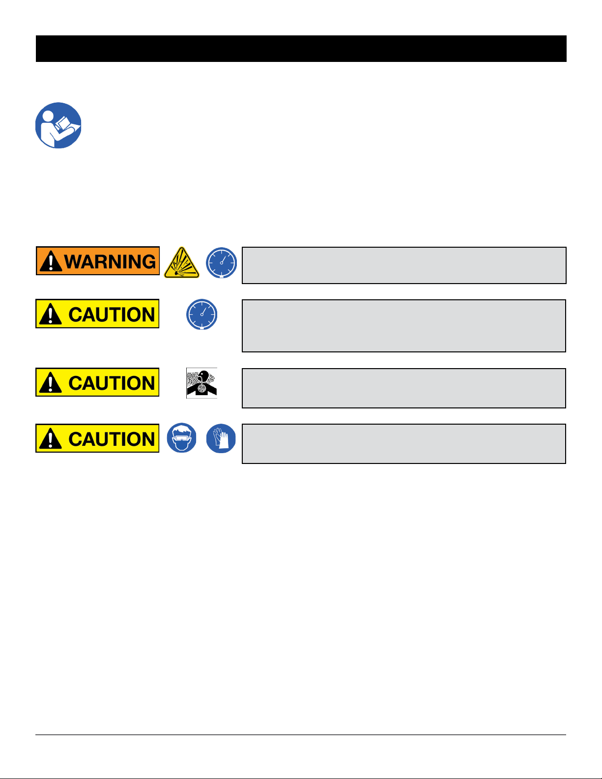
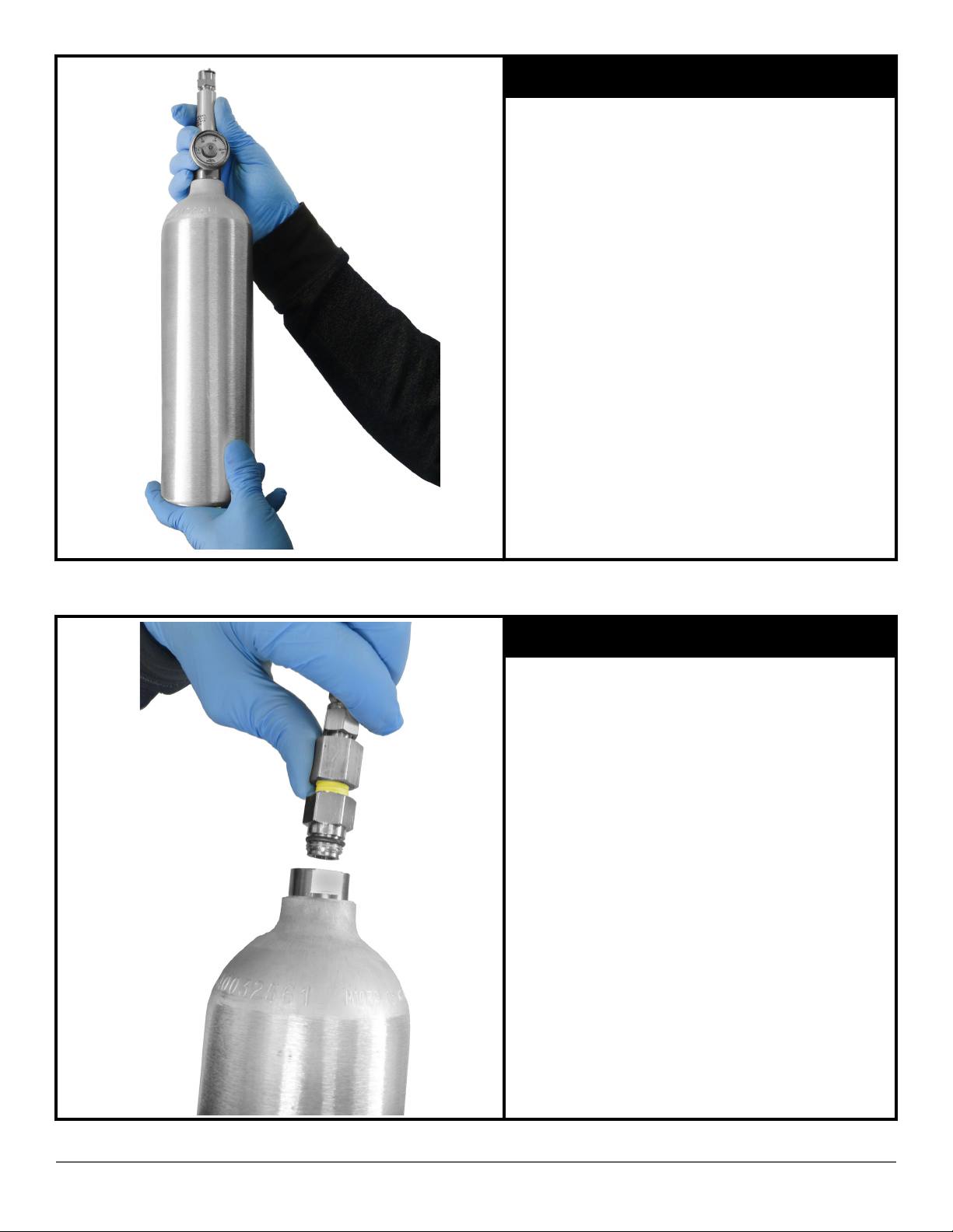
P1012177 - Premium Helium Spray Gun Probe Kit with 1 Liter Cylinder:
This model includes a rellable high pressure aluminum cylinder with a precise, detacheable regulator.
Helium ow rate can be adjusted between 0 and 0.1 Standard Liters Per Minute (SLPM). The cylinder
is 3” diameter x 11” tall, has a 1000cc volume, and a burst pressure rating of 1800 psi. We recommend
it be lled normally to about 500 psig. This kit includes a rell adapter for relling the cylinder from a
larger supply tank (see relling instructions , p. 6). The 10 ft exible supply hose has C10 quick connect
ttings on either end to connect the cylinder’s regulator to the spray gun. Also included is a 1/4 turn
shutoff valve mounted on the gun, a 4” rigid stainless steel probe tip, and an 8” long exible probe tip.
Please contact us for additional cylinders.
SPRAY PROBE MODEL INFORMATION
Do not exceed the rated pressure of tank, cylinder,
regulator or supply hose.

HESP-02072023 - V 1.01 5
1. For gross leak testing, the helium spray output pressure can be adjusted between 0-5 psig.
2. For pin-pointing leak locations, use lower helium pressure.
3. Adjust spray pressure by placing the probe tip in a small glass or beaker of water. The probe tip
will release helium bubbles. Gauge the amount of helium being released by the frequency of the
bubbles and adjust the regulator accordingly.
4. When spraying helium over the test part, use the lowest practical ow of helium. For determining
if a leak exists, a larger ow may be appropriate. However, for pinpointing leak location, reduce
the ow of bubbles to around 1-3 bubbles per second when the probe tip is immersed in water.
5. To assist in pinpointing a leak location, spray the suspect area in short spurts. Note the response
time of the leak detector as well as the magnitude of the signal that appears. A short response time
and a large signal indicate a leak location close to the spray point.
6. When leak testing a part with multiple potential leak locations, start by spraying areas at the top
of the part and work down. Because helium rises, starting from the bottom or sides can cause a
misleading leak location.
7. Compressed air can be used to dissipate helium trapped on or near the part. This may help reduce
the helium signal to the leak detector to make leak location faster.
TECHNIQUES TO OBTAIN OPTIMAL RESULTS
1. All spray gun kits are supplied with both a rigid and a exible tip.
2. The rigid tip is used for general spraying.
3. The exible tip is easily bent for leak testing hard-to-reach areas.
4. Use care not to over-bend the exible tip, particularly near the nut which secures it to the gun.
5. Make sure the probe tip does not get plugged.
6. To change tips, unscrew the Swagelok nut at the gun and replace with the other tip (7/16” wrench).
Tighten the nut slightly past hand tight.
ABOUT PROBE TIPS

HESP-0207023 - V 1.01 6
STEP 1
Make sure the supply tank valve is closed.
In the following pages, step-by-step, detailed instructions are provided for safely relling the small
helium gas cylinder in our premium helium spray gun probe kit (P1012177).
hThe cylinder is shipped empty and must be lled
before it can be used.
hA regulated helium supply tank with supply hose
is required to ll or rell the kit’s small cylinder.
hThe helium supply hose must have a female 1/4
NPT connector termination.
hThe P1012177 kit includes a C10-to-male 1/4
NPT rell adapter with a built-in check valve, used
to connect the supply hose to the cylinder.
hEvacuation of the cylinder is not required to top
off or rell it.
HOW TO REFILL SMALL CYLINDERS
Supply Hose
Helium
Supply Tank
Tank
Valve
Regulator
Valve
Outlet
Valve
Tank GaugeOutlet Gauge
Parts of a Regulator

HESP-0207023 - V 1.01 7
STEP 2
Bleed off any residual pressure in the
regulator by opening the outlet valve (turn
counterclockwise).
Once the tank and outlet pressure gauges
are zero, close the outlet valve completely.
STEP 3
Apply teon tape to the NPT threads of the
rell adapter.

HESP-0207023 - V 1.01 8
STEP 4
Connect the rell adapter to the supply tank
hose.
Use a 7/8 and 13/16”, or two adjustable
wrenches.
STEP 5
Decrease the tank regulator valve until it
feels loose (turn counterclockwise).

HESP-0207023 - V 1.01 9
STEP 6
Get the cylinder from the spray probe kit.
Disconnect the regulator/gauge assembly
from the cylinder by spinning the cylinder off
of the regulator/gauge assembly.
Note: No tools are required - the assembly is
hand-tight.
The cylinder does not need to be empty - the
cylinder has an internal valve.
STEP 7
Spin the cylinder onto the helium supply
hose, hand-tight.
Note: Do not use tools to tighten.

HESP-0207023 - V 1.01 10
STEP 18
SLOWLY open the regulator valve to
increase outlet gauge pressure to 50psi (turn
clockwise).
STEP 9
STEP 8
SLOWLY open the supply tank valve.
The tank pressure gauge will increase (to
the pressure in the supply tank).

HESP-0207023 - V 1.01 11
STEP 10
STEP 18
Continue slowly opening the regulator valve
until the outlet gauge pressure reads 500-
1000psi (turn clockwise). Here the pressure
is set to 500psi.
Note: Although the cylinder’s maximum rated
pressure is 1800psi, it is recommended to ll
to a more conservative pressure.
Wait for one minute (1:00) to allow the
cylinder to ll. You may not hear the transfer
of gas.
STEP 11
SLOWLY open the outlet valve to allow helium
into the cylinder (turn counterclockwise).
Listen for any leaks. Correct if necessary.

HESP-0207023 - V 1.01 12
STEP 12
STEP 18
Decrease the tank regulator valve until it
feels loose (turn counterclockwise).
Note: The gauges will continue to show
pressure until the regulator is bled off later.
STEP 13
Close the outlet valve completely (turn
clockwise).

HESP-0207023 - V 1.01 13
STEP 14
Turn off the supply tank valve completely.
STEP 18
VERY SLOWLY begin to unscrew the
cylinder from the supply hose rell adapter.
When you hear gas hissing, STOP
UNSCREWING! This starts bleeding off the
gas in the the supply hose (only).
Initially, the supply hose is at the ll
pressure (500-1000psi). If the cylinder is
completely unscrewed before the hose
is completely bled, the cylinder could
become a missile, or the hose could whip
uncontrollably causing injury.
Wait until the hissing stops (several minutes)
before completely unscrewing the cylinder.
STEP 15

HESP-0207023 - V 1.01 14
STEP 16
To release pressure in the regulator (for
tank storage), open the outlet valve (turn
counterclockwise.
Both gauges will go to zero pressure.
Close the outlet valve. The tank is now in its
normally stored state.
STEP 17
Get the cylinder regulator/gauge assembly.
Spin the cylinder onto the assembly.
The pressure gauge on the cylinder shows
the ll pressure. Here it is 500 psi.
The cylinder rell procedure is complete.

HESP-0207023 - V 1.01 15
STEP 18
Once the kit’s quick connect spray hose is
connected to the cylinder and gun, it is ready
to be used for leak testing.
Use the knurled valve knob on the cylinder
regulator/gauge assembly to open and
adjust the helium to ow to the gun.
Ideal Vacuum Products, LLC.
5910 Midway Park Blvd NE
Albuquerque, NM 87109
Phone: (505) 872-0037
Fax: (505) 872-9001
Web: idealvac.com
This manual suits for next models
3
Table of contents